
Home / Blog
Blog
0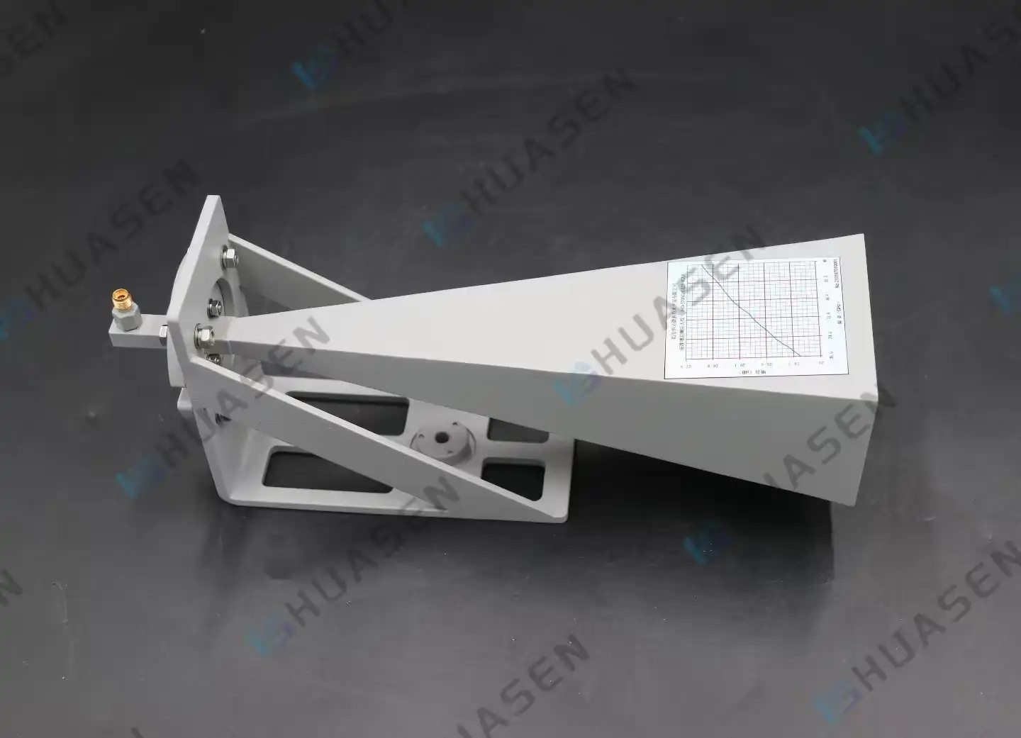
Standard gain horn antenna Characteristics and Specifications
It is important to know what makes a standard gain horn antenna different when choosing measurement-grade antennas for calibration labs, 5G test areas, or aerospace validation programs. These high-precision instruments have gain levels that are usually between 10 dBi and 25 dBi across certain waveguide bands. This is possible with aperture shapes that can be predicted mathematically. Standard gain horn antennas have low gain error, usually less than 0.3 dB. This makes them the standard for traceability in antenna measures, EMC tests, and radar cross-section characterisation in fields that need consistent, proven performance. Broadband horns that can be used for many things, on the other hand, give up accuracy for frequency range.VIEW MORE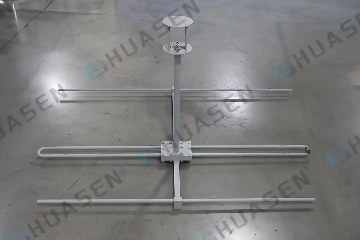
Why Choose a Yagi Antenna for Directional Coverage?
Using a Yagi antenna for linear coverage gives you the best signal focus, high gain, and interference avoidance, all of which are necessary for point-to-point communication links in tough industrial settings. RF energy is focused into a narrow beam by the Yagi-Uda design. This makes sure that signals can be sent reliably across VHF, UHF, and microwave bands. System designers, original equipment manufacturers, and procurement managers in radar, satellite, and telecommunications can use this antenna layout to get accurate signals at a low cost. The Yagi antenna is a tried-and-true way to get better directional performance in complex RF environments, whether you're building 5G backhaul networks, marine communication systems, or wireless test sets.VIEW MORE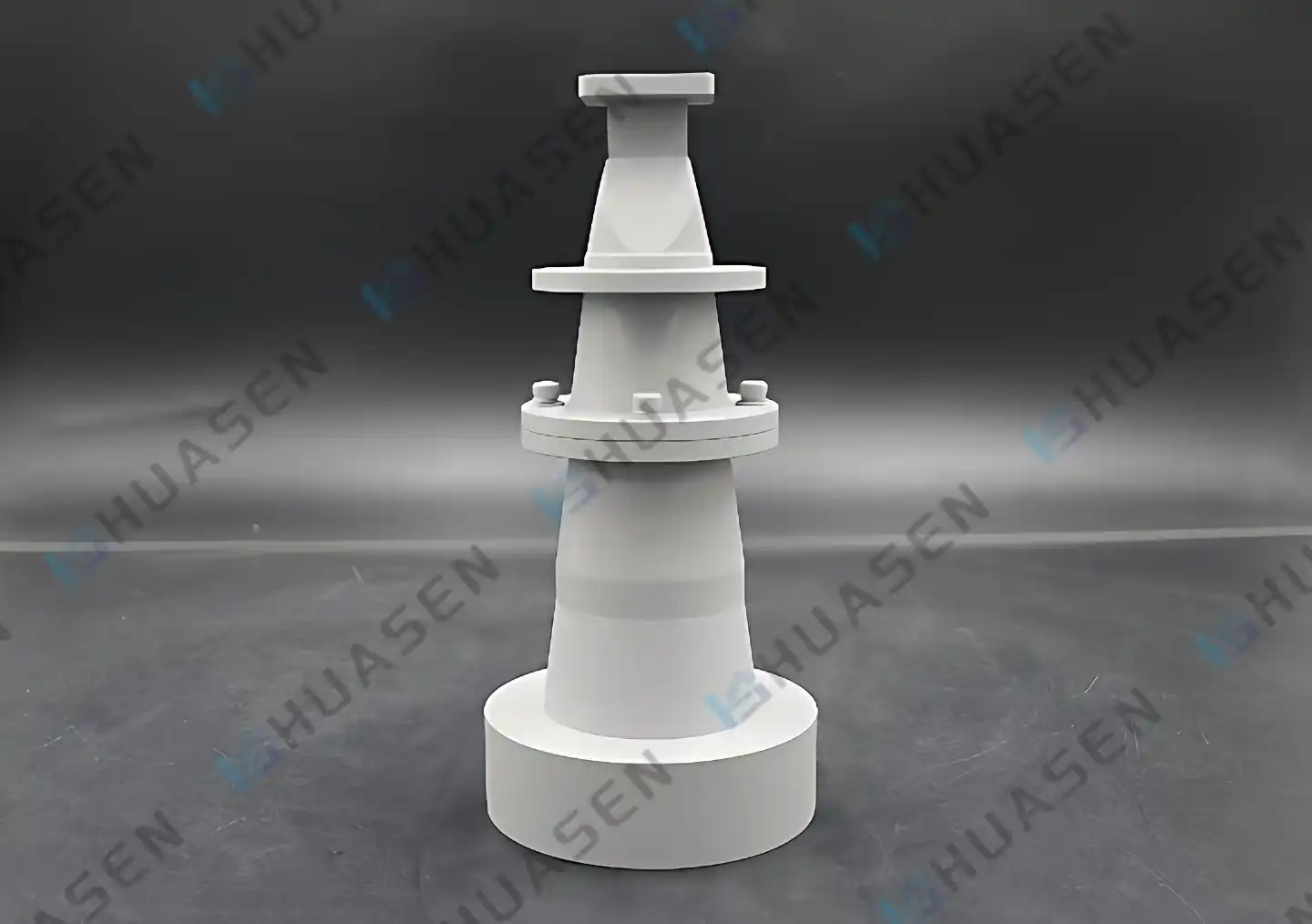
Why Use a Corrugated Conical Horn Antenna as a Feed?
The balanced HE11 hybrid mode, which results in uniform beam patterns with almost no cross-polarization, is produced by corrugated conical horn antennas, making them excellent feed elements. This one-of-a-kind feature gets rid of the pattern distortion that happens in smooth-walled horns, giving you better spillover efficiency and phase center stability over a wide range of bandwidths. Their rotationally uniform radiation properties make them essential for reflector systems that need the highest gain-to-noise temperature ratios and the least amount of sidelobe contamination in places like precision measurement and satellite communications.VIEW MORE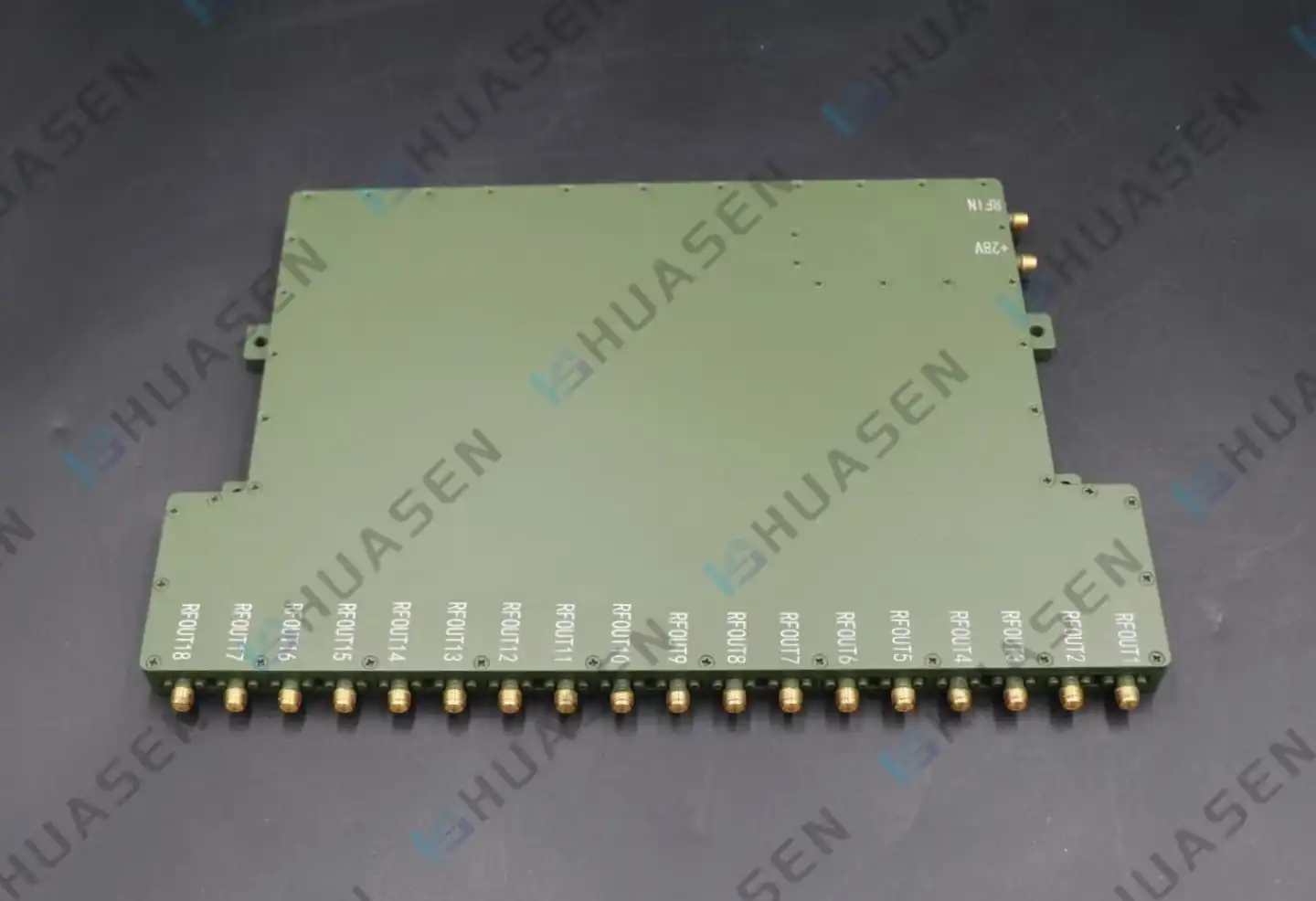
What Is a DC Power Amplifier in RF Signal Systems?
In RF signal systems, a DC Power Amplifier is a precise mechanical device that boosts weak radio frequency signals by using direct current as its main power source. It gives a stable, adjustable output across a wide frequency range. Instead of using AC-to-DC modules like most amplifiers do, these units take a DC input straight and turn it into boosted RF energy with very little distortion. The DC Power Amplifier is an important part of radar systems, satellite communications, internet infrastructure, and test equipment because it ensures that signals are stable and that power stays stable. This amplification technology solves some of the most important problems in current wireless systems by keeping linear gain, lowering phase noise, and making sure that the power supply stays steady even in the most demanding situations.VIEW MORE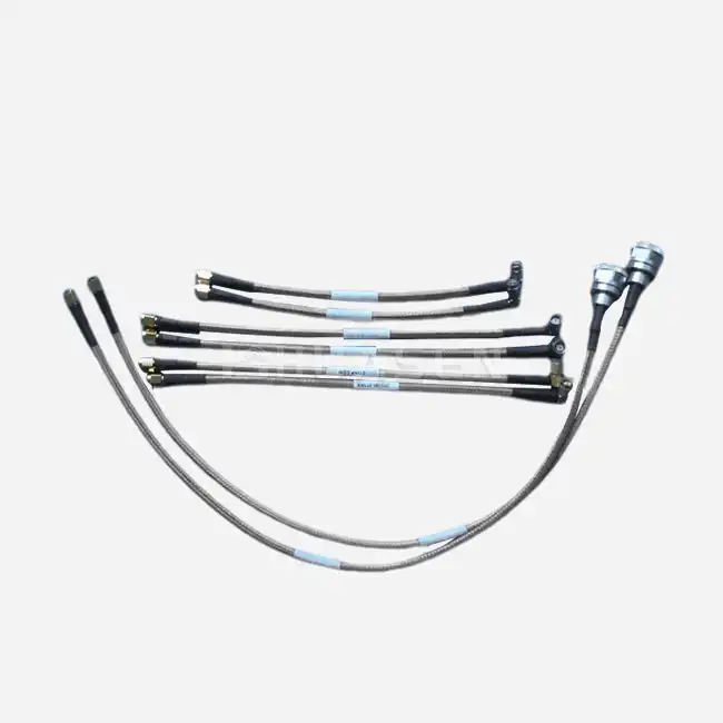
How Does Coax Cable Affect RF Signal Performance?
Coax Cable is the artery that connects RF parts, and the way it's made directly affects the quality of signals in radar, aircraft, and telecommunications systems. At frequencies from DC to 60GHz, even small flaws in the line can cause attenuation, phase distortion, and impedance mismatches that make the system work less well. We've seen over many years of engineering work that the dielectric material, shielding design, and connector contact of the wire decide whether a 5G base station gets its maximum throughput or a phased array radar keeps its phase coherence. When buying teams understand these connections, they can choose assemblies that meet the mechanical and environmental needs of mission-critical uses while still protecting the security of the signals.VIEW MORE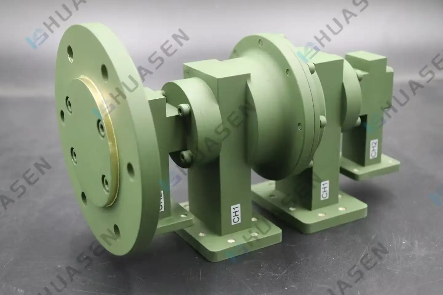
Military-Grade Dual Channel Rotary Joint Standards and Specifications
Military-grade Dual Channel Rotary Joints are precise electrical parts that let RF signals travel continuously across two separate channels while the joint rotates 360 degrees. These gadgets are made to meet strict military standards, such as MIL-STD-202 for tests in harsh environments, MIL-STD-810 for durability, and MIL-STD-461 for controlling electromagnetic interference. Meeting these requirements makes sure that Dual Channel Rotary Joints work well in defense radar systems, satellite communication platforms, and electronic warfare applications that need to send multiple frequencies at the same time without signal loss.VIEW MORE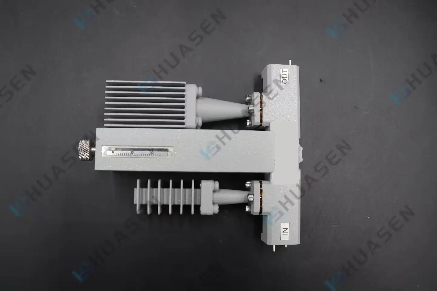
Coaxial Variable Attenuator: Step vs Continuously Variable
You can pick either step or continuously changeable coaxial variable attenuators based on how precise or flexible you need them to be for your purpose. Step attenuators give clear, consistent reduction values, which are great for standardized testing settings where accuracy is key. Models that are continuously variable give an endless range of adjustments, which is important for real-time signal leveling in dynamic RF settings. The main job of both kinds of devices is to change the signal intensity without changing the shape of the waveform. If procurement teams know how these devices work differently, they can better match the features of devices to the needs of the system. This is true whether they are setting up a 5G base station test bench or putting in place radar countermeasure gear.VIEW MORE
Choosing End Launch Waveguide to Coaxial Adapter
To pick the correct End Launch Waveguide to Coaxial Adapter, you need to know the frequency range of your system, how much power it needs, and which interfaces it works with. These precise RF parts move microwave energy between rectangular waveguides and coaxial transmission lines with a straight shape. They do this with very little insertion loss and great VSWR performance. If you choose adapters from companies that have a track record of skill in mode conversion, strong material quality, and full customization support, you can be sure that your phone, radar, or satellite system will work reliably in harsh environments and meet important standards for signal integrity and mechanical durability.VIEW MORE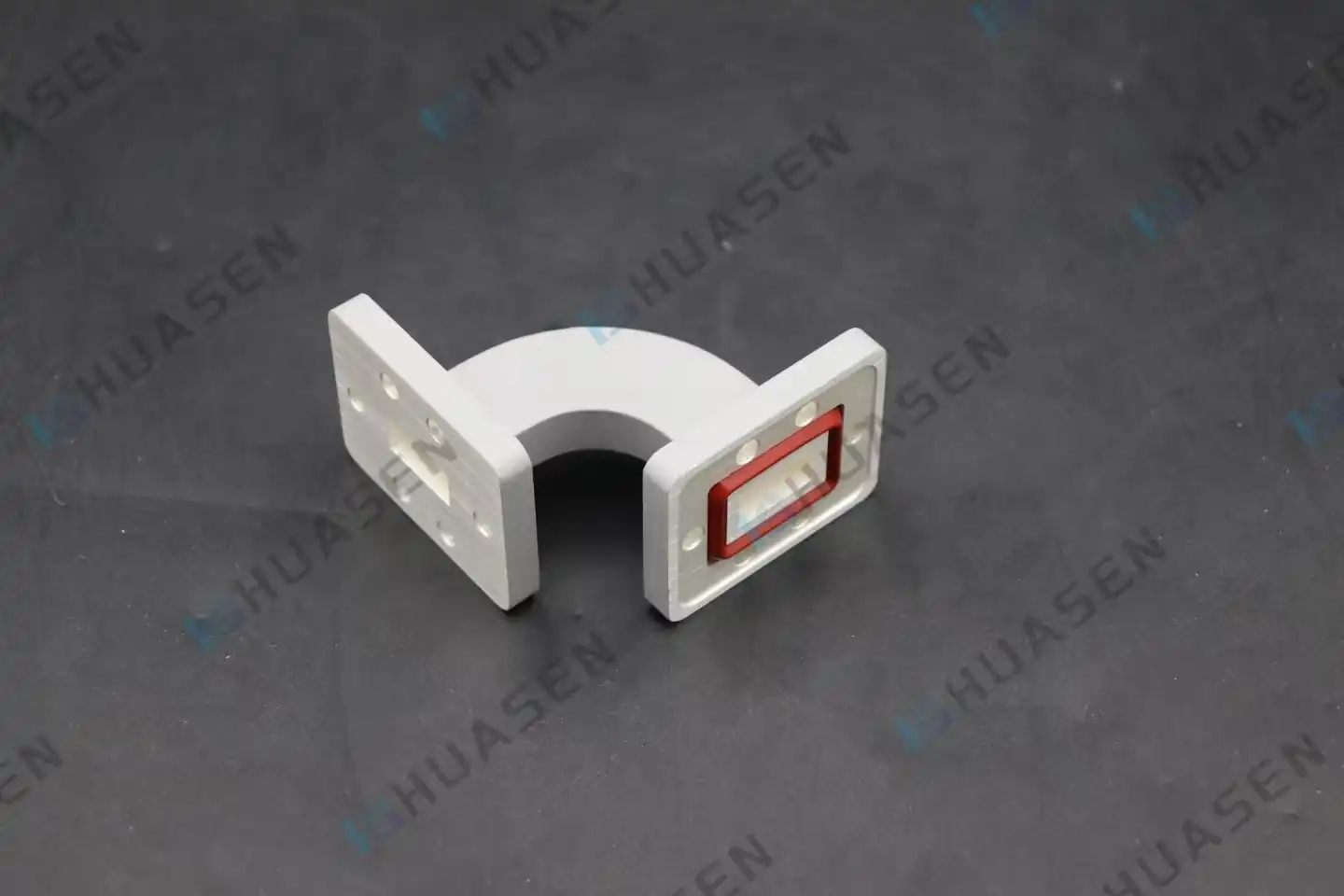
Manufacturing Accuracy in Bend Waveguide
The accuracy with which Bend Waveguide components are made directly affects how well they transmit signals, how well they work, and how reliable the system is in high-frequency RF uses. It doesn't matter what kind of bend it is—an E-plane bend, an H-plane bend, a mitered corner, or a double-bend—a Bend Waveguide needs to have exact dimensions, smooth internal surfaces, and exact curve radii to keep return loss and insertion loss as low as possible. It only takes very small changes in wall thickness, corner angles, or surface roughness to cause unwanted echoes, mode conversion, or power loss, especially at millimeter-wave frequencies. Accurate production needs strict process control, advanced machining techniques, and strict testing methods to make sure that every part meets the high standards needed for 5G infrastructure, radar systems, satellite communications, and aerospace applications.VIEW MORE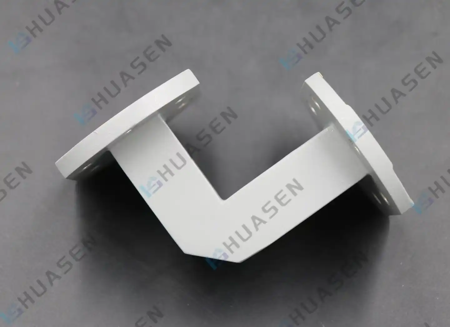
Mitered Bend Waveguide Fabrication Methods
To guarantee minimal signal reflection and best electromagnetic performance, Mitered Bend Waveguide fabrication requires precise engineering. The process of making something includes very precisely controlled grinding steps that make 45-degree cuts and keep tight tolerances on dimensions. Important factors like VSWR and insertion loss are directly affected by how well the device is made. Modern methods use CNC cutting and advanced plating methods to make waveguide parts that meet strict requirements for 5G infrastructure, satellite communication systems, and radar sites that can't risk dependability.VIEW MORE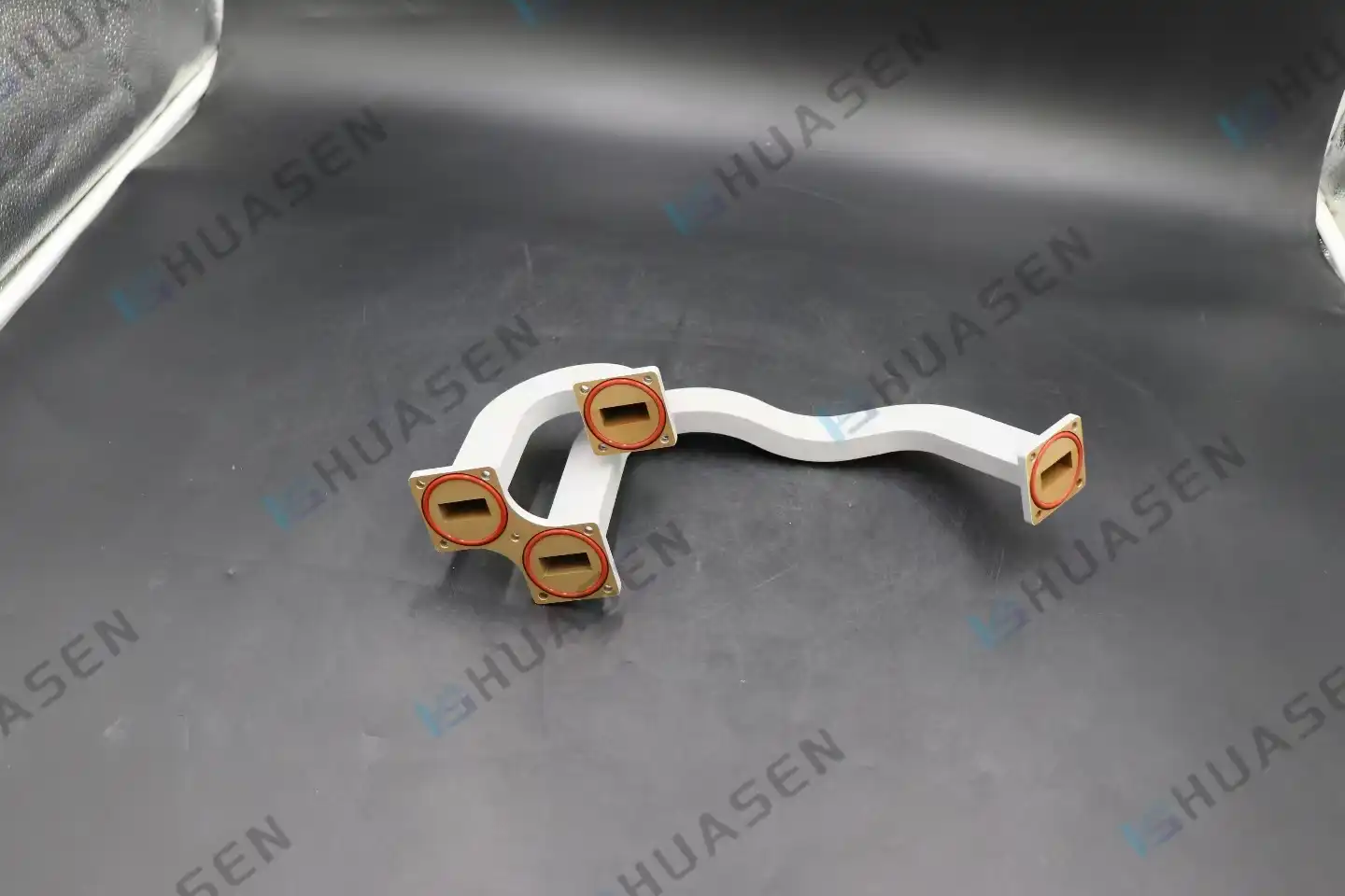
Multi Bend Waveguide for Complex Routing
Engineers always have to figure out how to get microwave energy around hurdles without lowering performance when they have to send high-frequency messages through small radar systems, satellite transponders, or 5G base stations. Multi Bend Waveguide systems solve this issue by combining several precise bends into a single stiff structure. This gets rid of lossy connections and keeps the signal integrity even in the smallest installation areas. These unique parts give modern telecommunications and aircraft systems the routing freedom they need while keeping the low insertion loss and high power handling capabilities that are necessary for mission success.VIEW MORE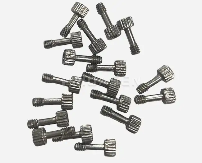
Waveguide Screw Installation Guide
Installing waveguide screws correctly is fundamental to maintaining signal integrity in RF and microwave systems. These specialized fasteners differ significantly from standard machine screws—they demand precise torque control, proper thread engagement, and careful attention to material compatibility. Whether you're assembling 5G base station components, satellite payloads, or radar systems, understanding the nuances of waveguide screw installation ensures optimal electrical performance, prevents passive intermodulation distortion, and extends component lifespan. This guide walks you through industry best practices that system integrators and equipment manufacturers rely on daily.VIEW MORE
- 1
- 7
- 8
- 9
- 10
- 11
- 60
Total 60 pages
