
Home / Blog
Blog
0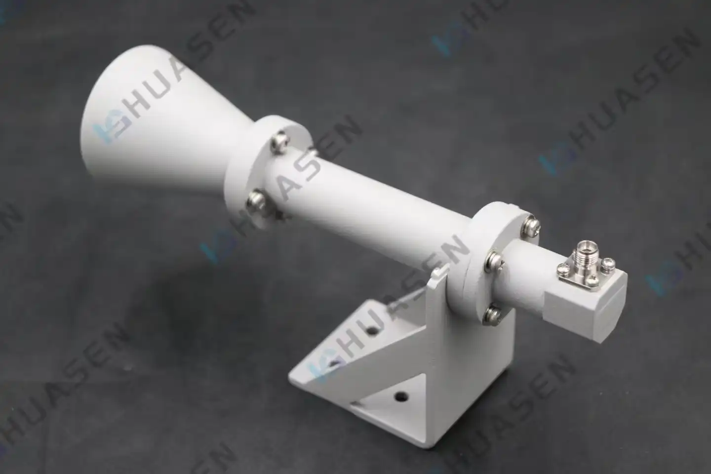
How Circularly Polarized Horn Antenna Reduces Polarization Mismatch?
Circularly Polarised Horn Antennas successfully lower polarisation mismatch by using an electric field vector that rotates continuously. This keeps signal reception stable no matter what direction the antenna is facing. In linearly polarised systems, signal alignment is very important. But these advanced antennas get rid of the orientation reliance that makes signals weaker. The circular polarisation technique makes sure that signals sent and received stay well coupled even if the antennas are not in the same place. This is why they are essential in dynamic communication environments where polarisation stability has a direct effect on system performance and reliability.VIEW MORE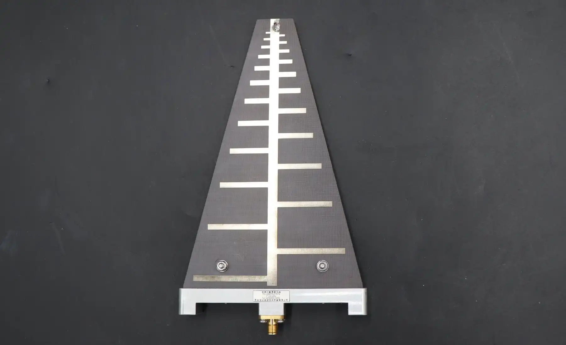
Log Periodic Antenna Applications in EMC and Spectrum Monitoring
The Log Periodic Antenna is an essential tool for engineers who need to quickly and accurately test for electromagnetic compatibility and spectrum monitoring across a wide range of frequency bands. When it comes to EMC testing, these high-tech broadband directional antennas work really well because they have stable gain and cover a lot of frequencies. Log periodic antennas work continuously across a wide frequency range, unlike traditional narrow-band antennas that need to be switched on and off a lot during testing. This makes them important for modern EMC compliance verification and real-time spectrum surveillance applications.VIEW MORE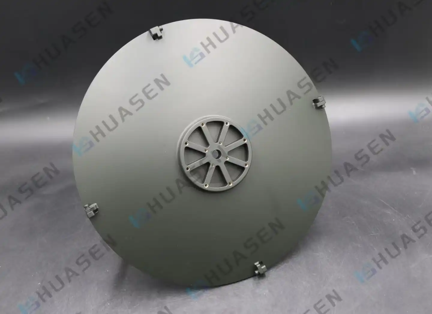
Parabolic Antenna vs Horn Antenna: Use Case Comparison
When engineers and procurement professionals compare parabolic antenna and horn antenna solutions, they need to look at the different operational characteristics that describe the best ways to use each technology. Parabolic antennas use curved reflector surfaces to direct electromagnetic energy into very narrow beams. This gives them great gain performance for communication over long distances. Horn antennas use flared waveguide structures that give them a moderate gain and wider coverage patterns. This makes them useful for testing in the lab and for broadband uses. Understanding these basic differences helps you make smart choices for your specific project needs, ensuring the best signal performance while balancing cost and installation difficulty in a wide range of industrial settings.VIEW MORE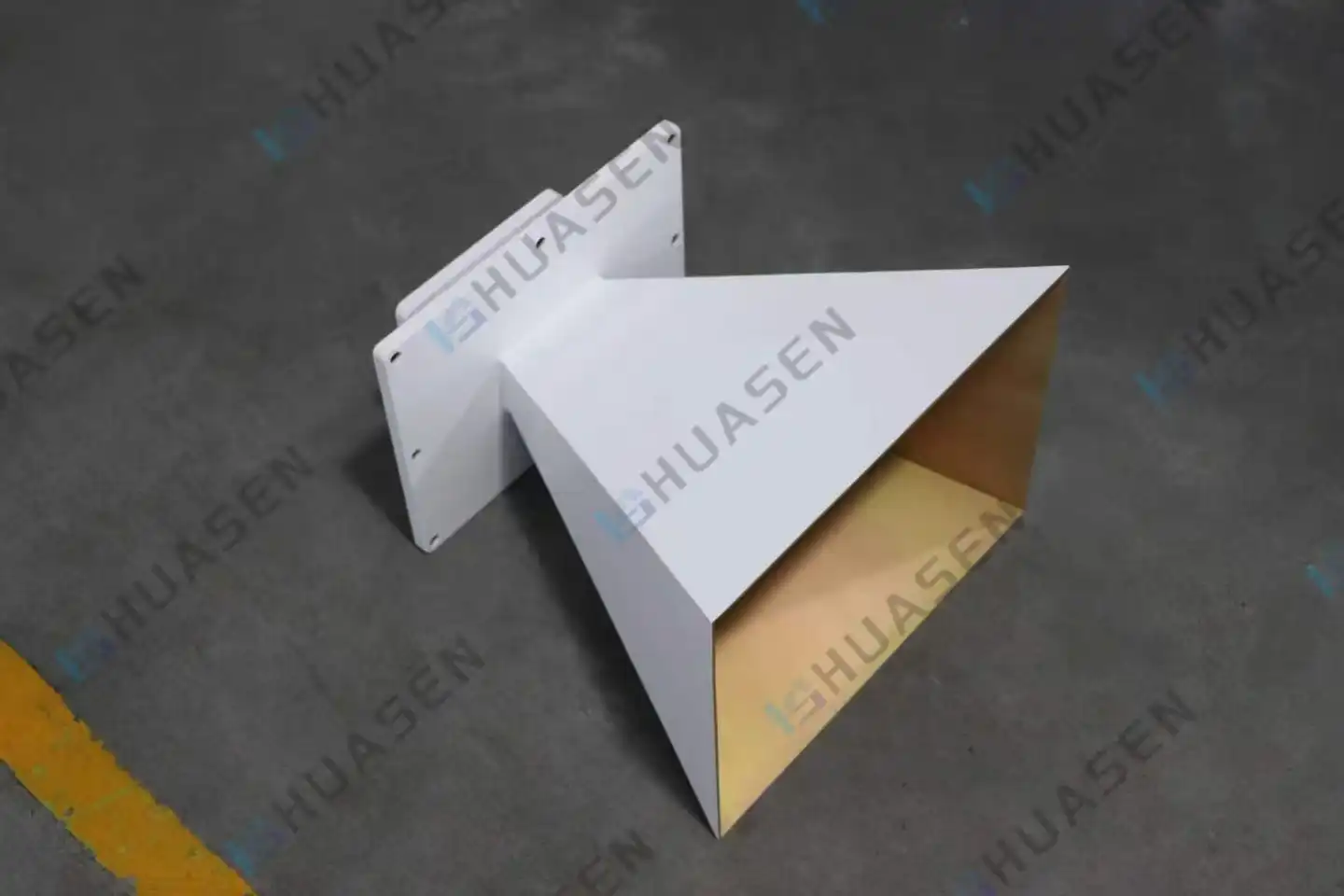
Pyramidal Horn Antenna in EMC and Field Strength Measurement
Pyramidal horn antennas are the best way to measure field strength and electromagnetic compatibility (EMC) in a wide range of businesses. These special waveguide horn antennas have a unique conical flare that grows in both electric and magnetic field sizes. This makes the impedance match between the waveguide feeds and free space perfect. Because they have consistent radiation patterns, high gain, and a strong build, they are essential for compliance testing, antenna calibration, and accurate field readings in both lab and factory settings.VIEW MORE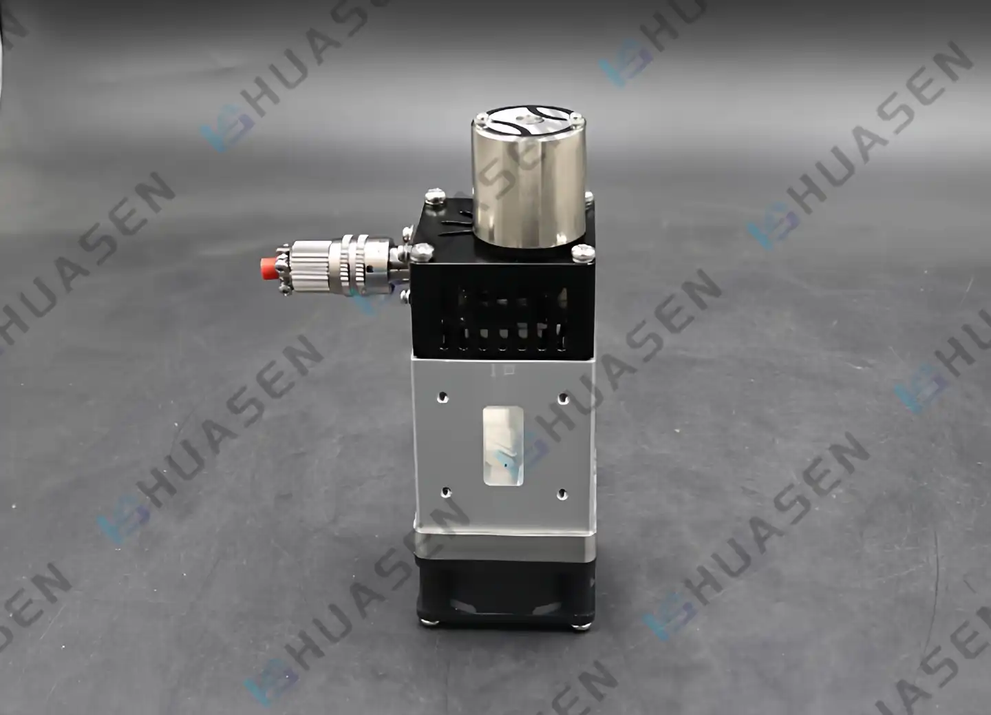
Single-Pole vs Single-Throw Electric Waveguide Switch Differences
When choosing RF parts for important communication systems, it's important to know the difference between single-pole and single-throw designs. A single-pole waveguide switch has one input port and several output choices, which lets signals go in different directions. A single-throw configuration, on the other hand, has one fixed setting that switches between two states, usually on and off. In microwave systems, the pole count determines how complicated the route is, and the throw count determines the switching states that can be used. Picking the right waveguide switch design has a direct effect on how flexible the system is, how well the signals work, and how well it works overall in demanding situations.VIEW MORE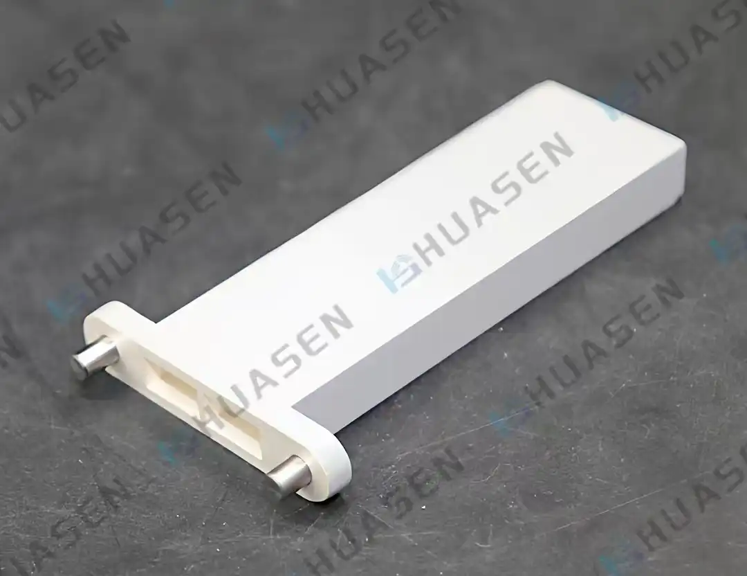
Waveguide Termination vs Dummy Load Differences
What is the difference between waveguide terminations and dummy loads? This is a very important question for engineers and system builders who work on RF and microwave systems. Waveguide terminations and fake loads are both made to stop signal reflections and take in electromagnetic energy. Waveguide terminations connect to waveguide transmission lines and are made for high-frequency uses. Dummy loads, on the other hand, connect to coaxial plugs and can handle a wider range of power levels. Figuring out these differences is important for getting the best results in testing, phone systems, and radar systems, where the security of the system depends on the integrity of the signals.VIEW MORE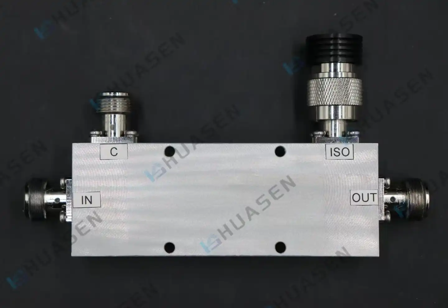
Microstrip vs Coaxial Directional Coupler Selection for RF Engineers
When selecting between microstrip and coaxial directional couplers, RF engineers must evaluate critical performance parameters, including frequency range, power handling capacity, insertion loss characteristics, and environmental resilience requirements. Microstrip directional coupler designs excel in compact applications requiring cost-effective integration within printed circuit boards, typically operating efficiently from 1-40 GHz with moderate power levels. Coaxial configurations deliver superior power handling capabilities, broader bandwidth coverage, and enhanced mechanical durability, making them indispensable for high-power transmission systems and precision measurement applications where signal integrity cannot be compromised.VIEW MORE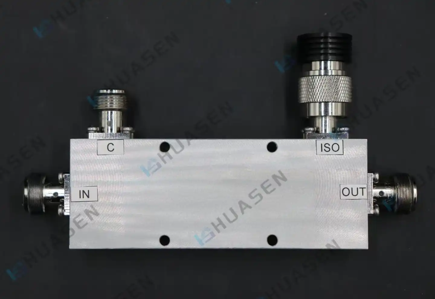
Directional Coupler Applications in Radar, Aerospace, and RF Testing
A directional coupler is a basic passive directional coupler RF part that picks up electromagnetic signals moving in certain directions in communication systems. Engineers can use these high-tech tools to check signal integrity, measure VSWR, and keep an eye on power levels without interfering with the main signal line. This is done by the directional coupler's electromagnetic coupling mechanisms, which separate the forward and reverse propagation directions very well while extracting exact signal fractions.VIEW MORE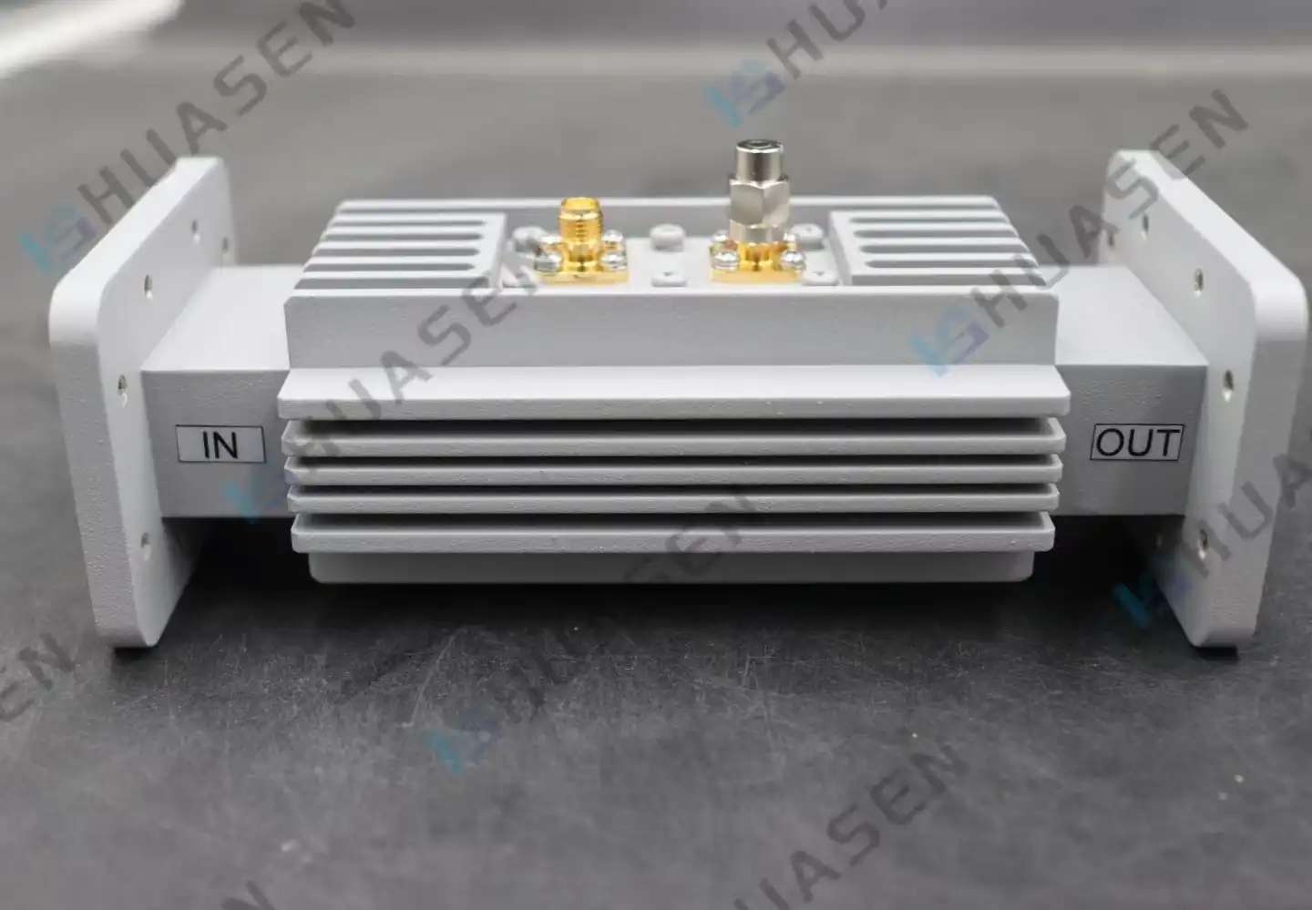
Waveguide Loop Coupler vs Directional Coupler in Microwave Systems
When engineers build microwave systems for radar, satellite communications, waveguide loop couplers,or telecommunications, they have to make important choices about which parts to use. When it comes to high-power applications, the choice between a Waveguide Loop Coupler and standard directional couplers has a big effect on how well the system works. Because they can handle more power and have less insertion loss, waveguide loop couplers are necessary for uses that need to sample signals precisely without affecting the integrity of the main line. Understanding these differences is important for making sure that systems are designed well and work reliably in a wide range of business settings.VIEW MORE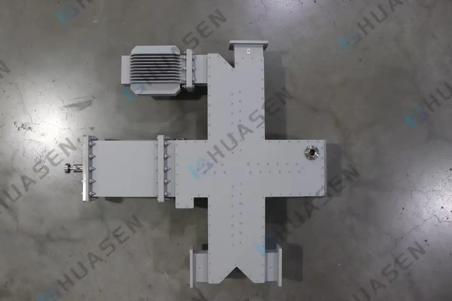
Waveguide Power Divider Applications in Radar, Satellite, and RF Testing
In radar, satellite, and RF testing, waveguide power dividers are very important parts because they allow exact signal distribution with very little loss and great isolation performance. For high-frequency systems like military radars, satellite communication networks, and lab tests, these high-tech gadgets can handle the tough needs of those systems. Because they are so special, waveguide power dividers are needed in situations where they need to handle a lot of power, have low insertion loss, and keep the signal integrity across a wide frequency range.VIEW MORE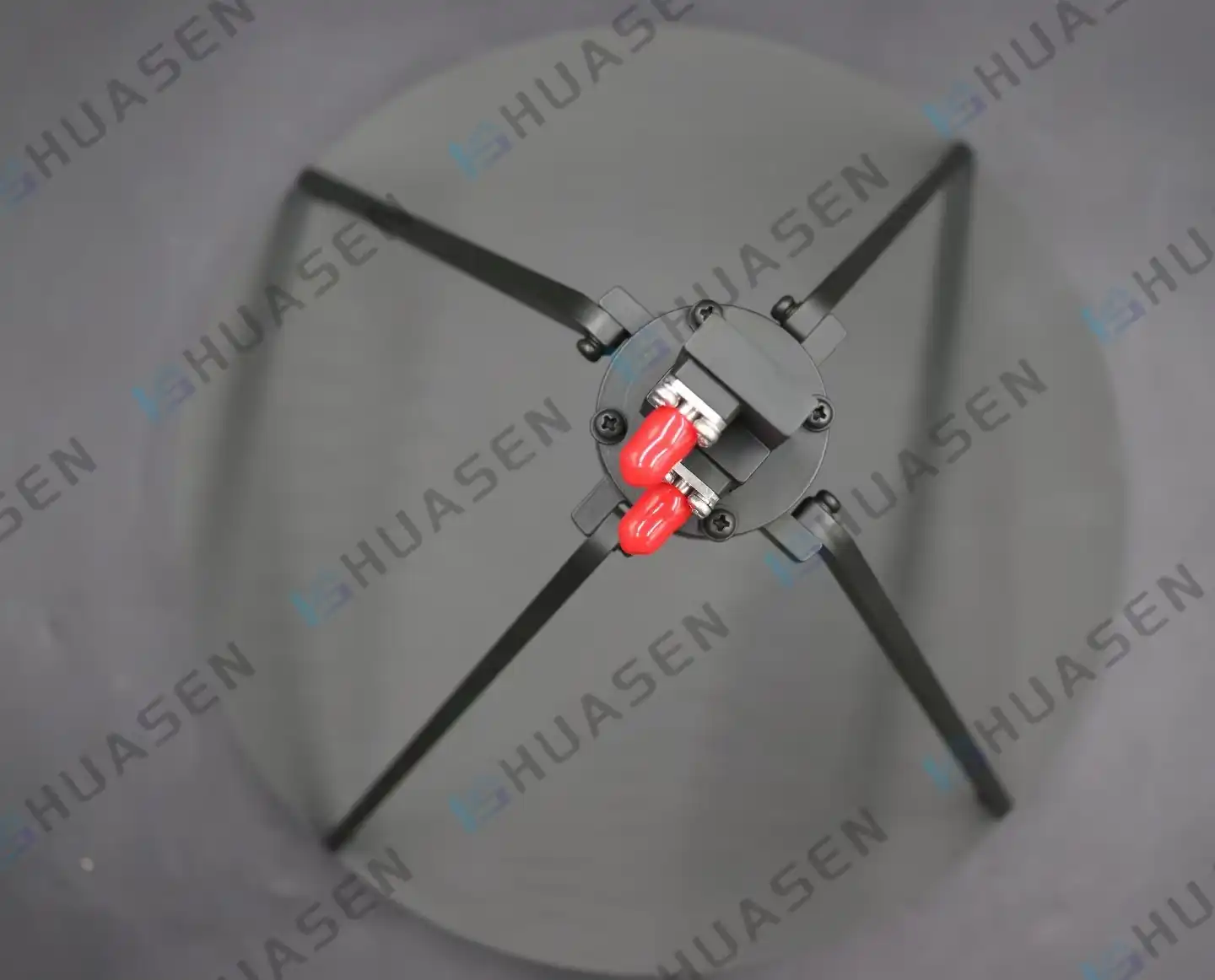
Parabolic Antenna Evolution and Modern Applications
The development of parabolic antenna technology is one of the most important steps forward in the sending and receiving of electromagnetic waves. In the past, antennas had trouble focusing in the right direction and getting strong signals. But parabolic reflectors changed the way wireless communications worked by focusing electromagnetic energy with a new level of accuracy. Modern parabolic antenna systems have changed from simple dish shapes to complex dual-polarised ones that can support 5G networks, satellite communications, and mission-critical radar uses in many different industries.VIEW MORE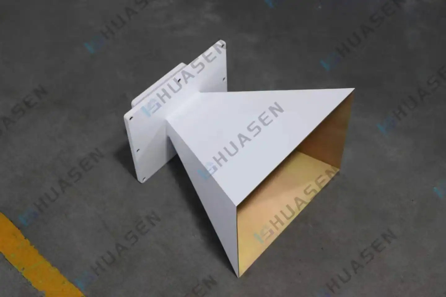
Why Pyramidal Horn Antenna Is Popular for RF Testing?
Because it can measure very accurately and point in the right direction, Pyramidal Horn Antenna technology has become the gold standard for RF testing in the defence, aerospace, and telecoms industries. These special antennas get rid of important impedance matching problems that come up with regular testing gear, giving constant VSWR performance below 1.5:1 over a wide range of frequency bands. Their pyramidal shape makes controlled beam patterns that are needed for accurate signal characterisation. This makes them essential for EMC compliance testing, antenna calibration, and material characterisation tasks where measurement accuracy has a direct effect on system performance and product certification.VIEW MORE
- 1
- 30
- 31
- 32
- 33
- 34
- 60
Total 60 pages
