Waveguide Loop Coupler vs Directional Coupler in Microwave Systems






2026-04-02 21:14:14
When engineers build microwave systems for radar, satellite communications, waveguide loop couplers,or telecommunications, they have to make important choices about which parts to use. When it comes to high-power applications, the choice between a Waveguide Loop Coupler and standard directional couplers has a big effect on how well the system works. Because they can handle more power and have less insertion loss, waveguide loop couplers are necessary for uses that need to sample signals precisely without affecting the integrity of the main line. Understanding these differences is important for making sure that systems are designed well and work reliably in a wide range of business settings.
Understanding the Fundamentals of Waveguide Loop Couplers and Directional Couplers
How Waveguide Loop Couplers Operate
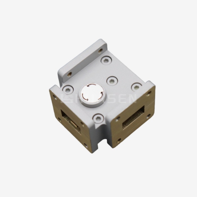
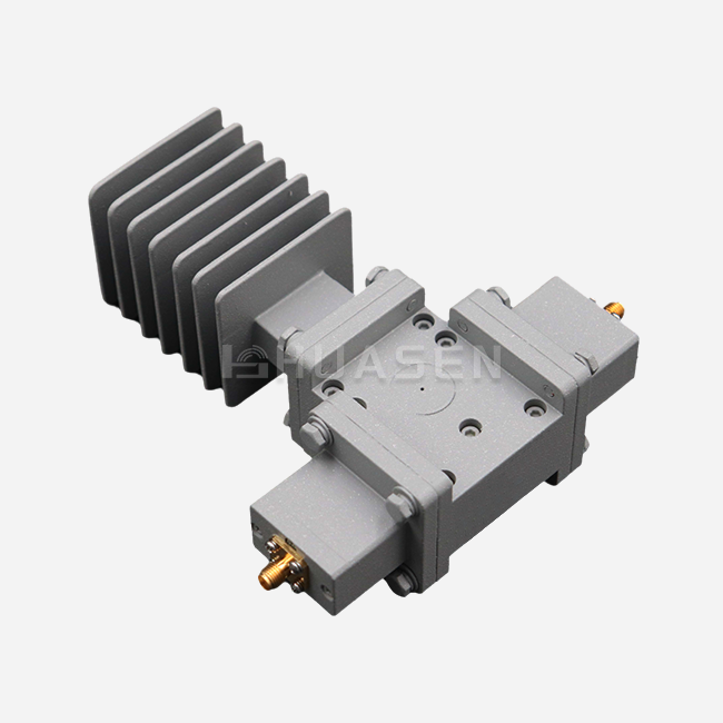
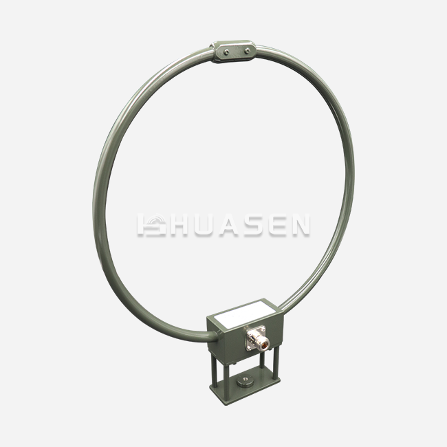
What Waveguide Loop Couplers Do: Waveguide Loop Couplers work by inserting a carefully designed loop antenna into the main waveguide communication line. The magnetic field (H-field) inside the waveguide construction is picked up by this loop, which changes electromagnetic energy into a coaxial output signal. Unlike other coupling methods, the loop design lets field engineers fine-tune coupling values during deployment by changing the probe's depth and spin. The basic idea behind how it works is electromagnetic induction, and the loop antenna picks up a certain amount of power moving through the main waveguide. This sampling method doesn't get in the way of the signal and still lets you do accurate tracking. The coupling factor is based on where the loop is placed within the waveguide and can be anywhere from 20dB to 60dB, depending on the needs of the application.
Traditional Directional Coupler Variants
There are different ways to create directional couplers, such as branch line, stripline, and microstrip. Branch line couplers use quarter-wave sections to couple in a certain way, while stripline versions use parallel transmission lines to move energy. Smaller options for low-power uses are available with microstrip couplers that are easy to add to printed circuit board assemblies. The main and secondary transmission paths interact with each other's electromagnetic fields to make these coupling mechanisms work. Performance qualities are set by the coupling factor and directivity parameters. Directivity shows how well the device can tell the difference between forward and reflected signals. In all working bandwidths, the normal range for directivity values is between 15dB and 25dB.
Comparative Analysis of Operational Mechanisms
The fundamental difference between these technologies lies in their energy transfer methods. Waveguide Loop Couplers utilize magnetic field coupling through a physical loop probe, while directional couplers employ distributed electromagnetic coupling along transmission line sections. This distinction affects power handling capacity, frequency response, and mechanical integration requirements. Loop couplers excel in high-power environments due to their concentrated sampling mechanism and robust construction. The loop's small physical size minimizes voltage breakdown risks compared to distributed coupling structures. Conversely, directional couplers offer broader bandwidth characteristics and easier integration into planar circuit designs, making them suitable for multi-frequency applications.
Practical Comparison: Waveguide Loop Coupler vs Directional Coupler
Performance Characteristics Analysis
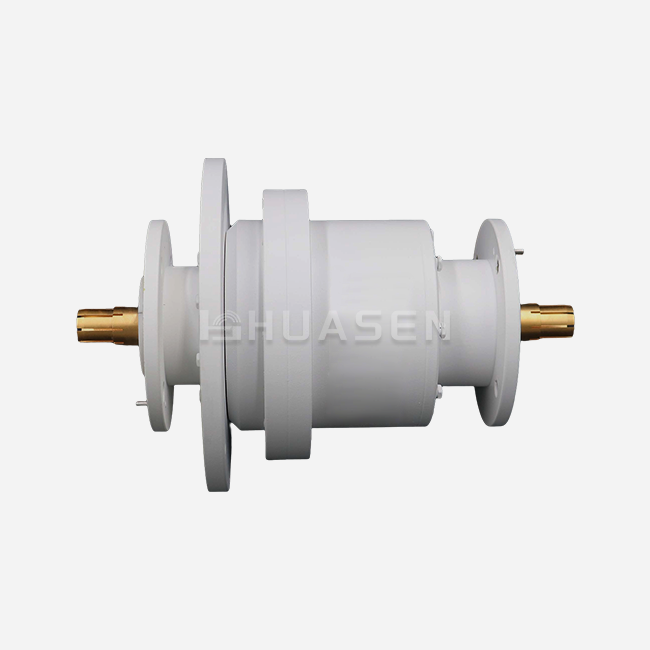
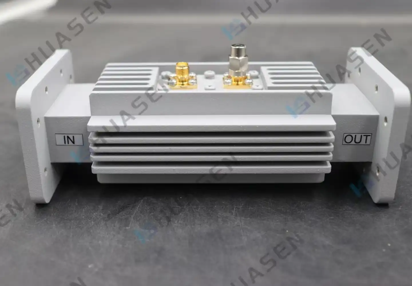
Waveguide Loop Couplers demonstrate exceptional performance in demanding environments where power handling and signal integrity remain paramount. The Huasen Microwave Waveguide Loop Coupler achieves VSWR specifications of ≤1.1 on the main line and ≤1.25 on the sub-line, ensuring minimal reflection losses. With directivity ≥15dB and coupling options spanning 20dB to 60dB, these devices accommodate diverse monitoring requirements across BJ9-BJ140 waveguide standards. The bandwidth limitation of ≤20% represents a focused design approach prioritizing performance over broadband coverage. This constraint proves advantageous in applications requiring precise frequency response within specific operational bands. The excellent sealing properties enable stable operation in harsh environmental conditions, addressing critical reliability concerns in outdoor and maritime installations.
Application-Specific Advantages
High-power radar systems benefit significantly from waveguide loop technology due to superior power-handling capabilities and low insertion loss characteristics. Naval and airborne radar installations rely on these components for automatic level control loops and VSWR protection circuits. The compact form factor addresses space constraints in cramped equipment compartments while maintaining robust performance under vibration and shock conditions. Directional couplers serve different operational niches, particularly in test equipment and lower-power distribution networks. Their integration flexibility makes them valuable in laboratory Loop Couplerenvironments where multiple coupling ratios and broad frequency coverage are essential. The planar construction simplifies manufacturing and reduces costs for high-volume production scenarios.
Design Constraints and Mitigation Strategies
Loop coupler implementations face mechanical complexity challenges related to probe positioning and environmental sealing. The adjustable nature of many designs requires careful calibration during installation to achieve the specified coupling accuracy. However, this adjustability becomes an advantage when field conditions demand coupling value modifications after deployment. Traditional directional couplers encounter bandwidth limitations and power handling constraints that restrict their applicability in high-power scenarios. Design engineers must balance coupling flatness across operational frequencies with physical size constraints. These limitations drive the selection toward specialized solutions like waveguide loop configurations when maximum performance is required.
Procurement Guide for Waveguide Loop Couplers and Directional Couplers
Key Selection Criteria
Procurement professionals must evaluate several critical parameters when selecting coupling components for microwave systems. Power handling requirements often determine the initial technology choice, with waveguide loop solutions preferred for megawatt-class applications. Frequency range compatibility ensures proper operation across intended bands, while mechanical interface requirements dictate connector and flange specifications. Coupling accuracy and stability affect measurement precision throughout system operation. The Huasen Microwave Waveguide Loop Coupler provides multiple coupling options from 20dB to 60dB, allowing system designers to optimize dynamic range and measurement sensitivity. Environmental specifications become crucial for outdoor installations where temperature cycling, humidity, and vibration exposure challenge component reliability.
Supplier Evaluation and Technical Support
Reliable suppliers demonstrate proven experience in high-frequency component manufacturing with appropriate quality certifications and testing capabilities. Technical support capabilities significantly impact project success, particularly during integration and commissioning phases. Comprehensive documentation, application notes, and responsive engineering assistance differentiate premium suppliers from commodity providers. Manufacturing quality control processes ensure consistent performance across production lots. Vector Network Analyzer verification, high-power burn-in testing, and dimensional inspection protocols validate component specifications before shipment. These quality measures prove essential for applications where component failure could compromise expensive system installations.
Procurement Best Practices
Bulk ordering considerations include lead time management, inventory optimization, and cost negotiations for large-volume purchases. Long-term supply agreements provide pricing stability and priority allocation during supply chain disruptions. Warranty coverage and after-sales service terms protect procurement investments while ensuring ongoing operational support. Sample evaluation programs allow engineering teams to validate component performance before committing to large-quantity purchases. This approach reduces technical risk while enabling optimization of system integration procedures. Collaborative relationships with suppliers facilitate customization requests and expedited delivery when urgent project requirements arise.
Technical Insights and Design Considerations for Waveguide Loop Couplers
Design Parameters and Performance Optimization
The effectiveness of waveguide loop couplers depends critically on several design parameters that influence coupling efficiency and system integration. Loop dimensions, positioning within the waveguide, and material selection affect both electrical performance and mechanical reliability. Proper loop sizing ensures adequate coupling while maintaining structural integrity under high-power conditions. Coupling uniformity across operational bandwidth requires careful attention to loop geometry and waveguide mode characteristics. The Huasen Microwave design achieves ≤20% bandwidth with excellent VSWR performance through optimized loop configuration. This focused approach delivers superior performance within specified frequency ranges compared to broadband alternatives that sacrifice precision for coverage.
Integration Methods and Installation Considerations
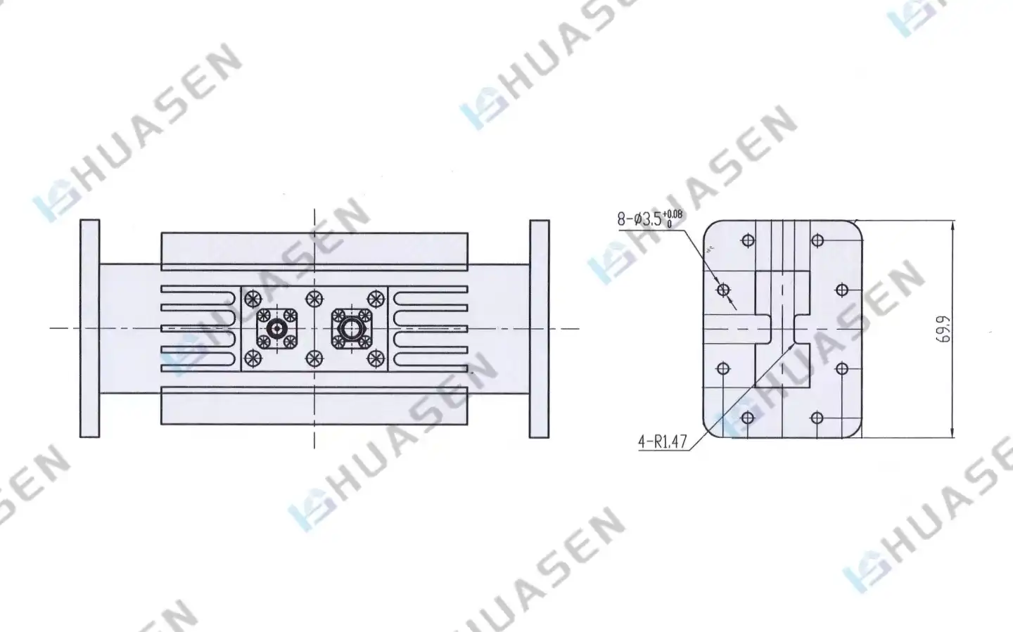
To successfully integrate waveguide loop couplers, you need to know about the need for both a mechanical interface and environmental safety. Waveguide standards from BJ9 to BJ140 are flange compatible, Loop Coupler,which means they can be used in a wide range of system designs. When torque specifications and sealing methods are followed correctly, RF leakage is stopped, and long-term reliability is maintained. Coaxial output connections have to work with measurement equipment interfaces and the way cables can be routed in equipment setups. Standard link types, such as SMA, N-type, and TNC, let you set up your system in a variety of ways. When routing signals, things to think about include how to account for cable loss and how easy it is to get to measurement ports for repair.
Comparative Technology Analysis
Alternative coupling technologies each present unique advantages and limitations compared to waveguide loop configurations. Cross-guide couplers offer excellent bandwidth performance but require significantly more mechanical space. Multi-hole designs provide good coupling uniformity but may introduce higher insertion losses in the main transmission path. Hybrid coupler networks enable power splitting functions beyond simple monitoring applications, but add complexity and cost to system designs. Microstrip and stripline alternatives suit lower-power applications where compact integration outweighs power handling requirements. Understanding these trade-offs guides optimal technology selection for specific application requirements.
Future Trends and Innovations in Microwave Coupler Technology
Technological Advancements in Materials and Design
New improvements in microwave coupler technology focus on wider frequency ranges and better power handling by using better materials and manufacturing methods. With new dielectric materials, temperature stability is better, and losses are lower over a wider frequency range. Precision machining lets you control tolerances more closely, which makes coupling precision and repeatability better. With additive manufacturing, it's possible to make parts with complex internal shapes that weren't possible with traditional machining. These new ideas make it possible to improve performance while lowering size and weight by optimising the spread of electromagnetic fields within coupling structures. But traditional waveguide loop designs still work best in high-power situations where dependability is very important.
Market Drivers and Demand Evolution
As more 5G networks are put in place and new 6G technologies come out, there is a greater need for precise tracking parts that can handle higher power levels and wider frequency ranges. Satellite transmission systems need coupling solutions that are reliable and work well in a wide range of temperatures and harsh environments. Defence and aerospace applications need more and more parts that are both high-performance and small enough to fit on platforms with limited room. Software-defined radios and adaptive antenna systems are becoming more popular. This makes room for coupling parts that are more flexible and easy to handle.
Strategic Procurement Considerations
Long-term plans for buying things need to take changing technology needs into account while still being able to work with current investments in infrastructure. When you work withWaveguide Loop Couplersuppliers who offer both standard goods and the ability to customise them, you have options as your system needs change. Putting money into tried-and-true technologies like waveguide loop couplers will keep them working while new technologies develop. Standardising parts across multiple projects simplifies inventory and training needs while taking advantage of the benefits of buying in bulk. But for certain applications, custom solutions may be needed, which can explain higher prices for better performance or specific needs.
Conclusion
Choosing between directional couplers and Waveguide Loop Couplers depends on the needs of the application. Each technology has its own benefits. Waveguide Loop Couplers work best in high-power settings that need low insertion loss and strong environmental performance. On the other hand, traditional directional couplers offer more bandwidth and coupling options for lower-power uses. Knowing these basic differences helps you make smart buying choices that improve system performance and long-term dependability for a wide range of microwave uses.
FAQ
1. What distinguishes a Waveguide Loop Coupler from conventional directional couplers?
A Waveguide Loop Coupler utilizes a physical loop antenna inserted into the waveguide to sample the magnetic field, providing superior power handling and minimal main line disruption. Conventional directional couplers rely on distributed electromagnetic coupling along transmission line sections, offering broader bandwidth but lower power capabilities.
2. Can coupling factors be adjusted after installation in loop coupler systems?
Many professional Waveguide Loop Coupler designs feature adjustable probe depth and rotation mechanisms, allowing field engineers to fine-tune coupling values within a ±3dB range. This adjustability enables precise calibration to match detector sensitivity requirements and compensate for system variations during commissioning.
3. What power levels can Waveguide Loop Couplers handle safely?
Quality Waveguide Loop Couplers handle megawatt-class power levels due to their concentrated sampling mechanism and robust construction. The small loop size operates in the magnetic field region where voltage breakdown is less likely compared to electric field probes, enabling safe operation in high-power radar and accelerator applications.
4. How does environmental sealing affect loop coupler reliability?
The Huasen Microwave Waveguide Loop Coupler incorporates excellent sealing properties that ensure stable operation in harsh environments, including marine, aerospace, and outdoor installations. Proper sealing prevents moisture ingress and maintains electrical performance across temperature cycling and vibration exposure.
5. What waveguide compatibility options exist for loop couplers?
Professional loop couplers support standard waveguide interfaces from BJ9 through BJ140, covering frequency ranges from L-band through Ka-band applications. This broad compatibility enables integration across diverse system architectures while maintaining consistent electrical performance and mechanical interfaces.
Partner with Huasen Microwave for Superior Coupling Solutions
Huasen Microwave Technology brings over three decades ofWaveguide LoopCouplerexpertisein precision microwave component manufacturing, specializing in high-performance Waveguide Loop Couplers that meet the demanding requirements of modern RF systems. Our advanced manufacturing capabilities and rigorous quality control processes ensure consistent performance across challenging applications from defense radar to satellite communications.
As a trusted Waveguide Loop Coupler manufacturer, we provide comprehensive technical support throughout the procurement process, from initial specification review to field deployment assistance. Our engineering team collaborates with your design requirements to optimize component selection and system integration for maximum reliability and performance.
Contact our sales team at sales@huasenmicrowave.com to discuss your specific coupling requirements and discover how our proven solutions can enhance your microwave system performance.
References
1. Pozar, David M. "Microwave Engineering, 4th Edition." John Wiley & Sons, 2011.
2. Collin, Robert E. "Foundations for Microwave Engineering, 2nd Edition." IEEE Press, 2001.
3. Montgomery, Carol G. "Technique of Microwave Measurements." MIT Radiation Laboratory Series, Volume 11, Boston Technical Publishers, 1963.
4. Ramo, Simon, John R. Whinnery, and Theodore Van Duzer. "Fields and Waves in Communication Electronics, 3rd Edition." John Wiley & Sons, 1994.
5. Rizzi, Peter A. "Microwave Engineering: Passive Circuits." Prentice Hall, 1988.
6. Saad, Tarek S. "Microwave Engineers' Handbook, Volume 1." Artech House, 1971.
Send Inquiry