
Blog
0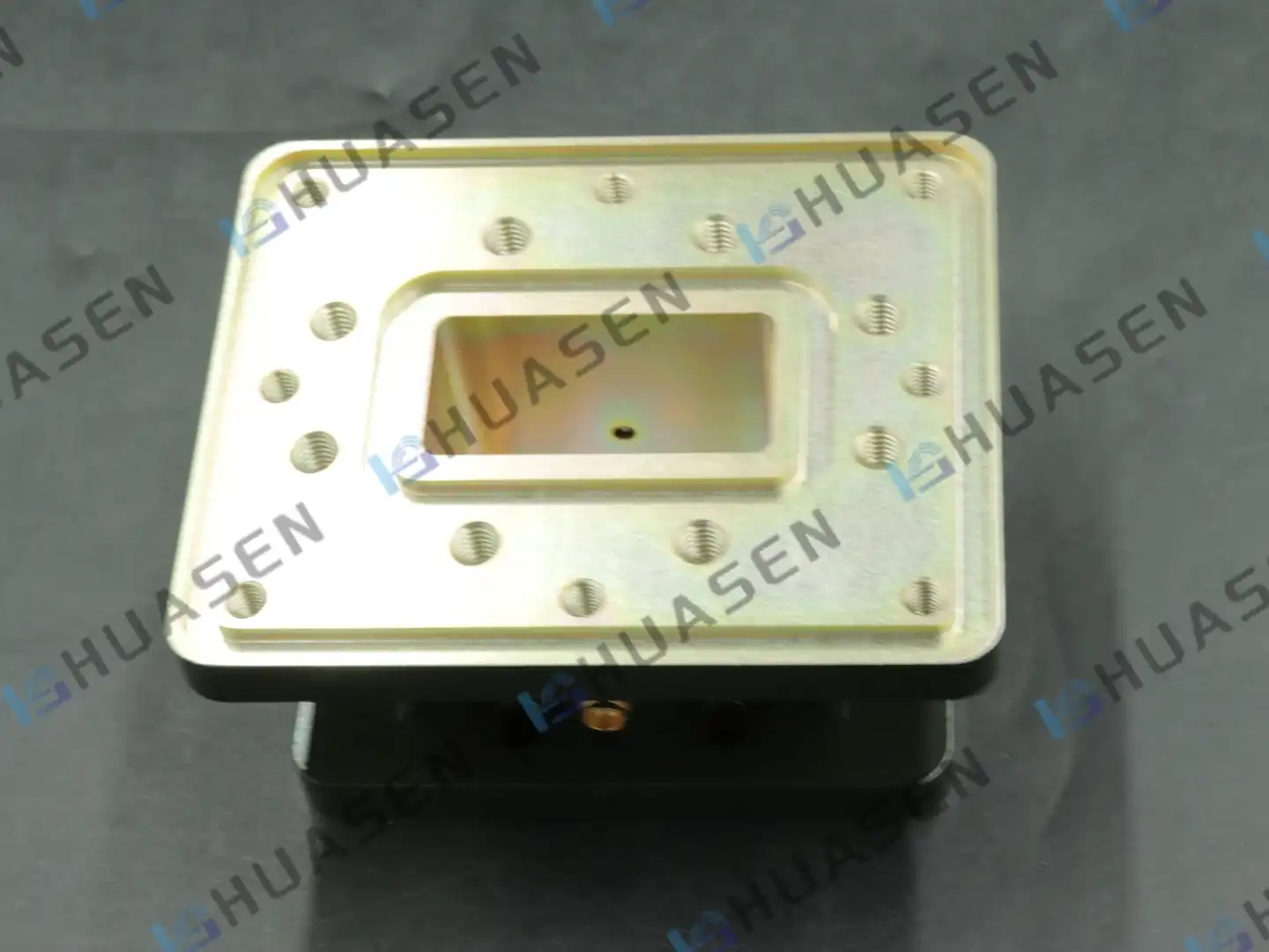
Leak Rate Testing Methods for Millimeter Wave Waveguide Pressure Windows
Engineers specifying waveguide windows for mission-critical radar, satellite uplink, or 5G infrastructure often ask, 'How can we ensure hermetic integrity under operating stress?' Testing these precise barriers' leak rate isn't just a quality check—it's essential to system dependability. Waveguide windows transfer RF energy while limiting moisture, pollutants, and pressure differentials between pressurised or vacuum-sealed locations and ambient conditions. Any tiny leak reduces dielectric strength, causes high-power arcing, and promotes component deterioration. This handbook helps procurement teams and system integrators choose millimetre-wave leak detection methods that safeguard performance and investment.VIEW MORE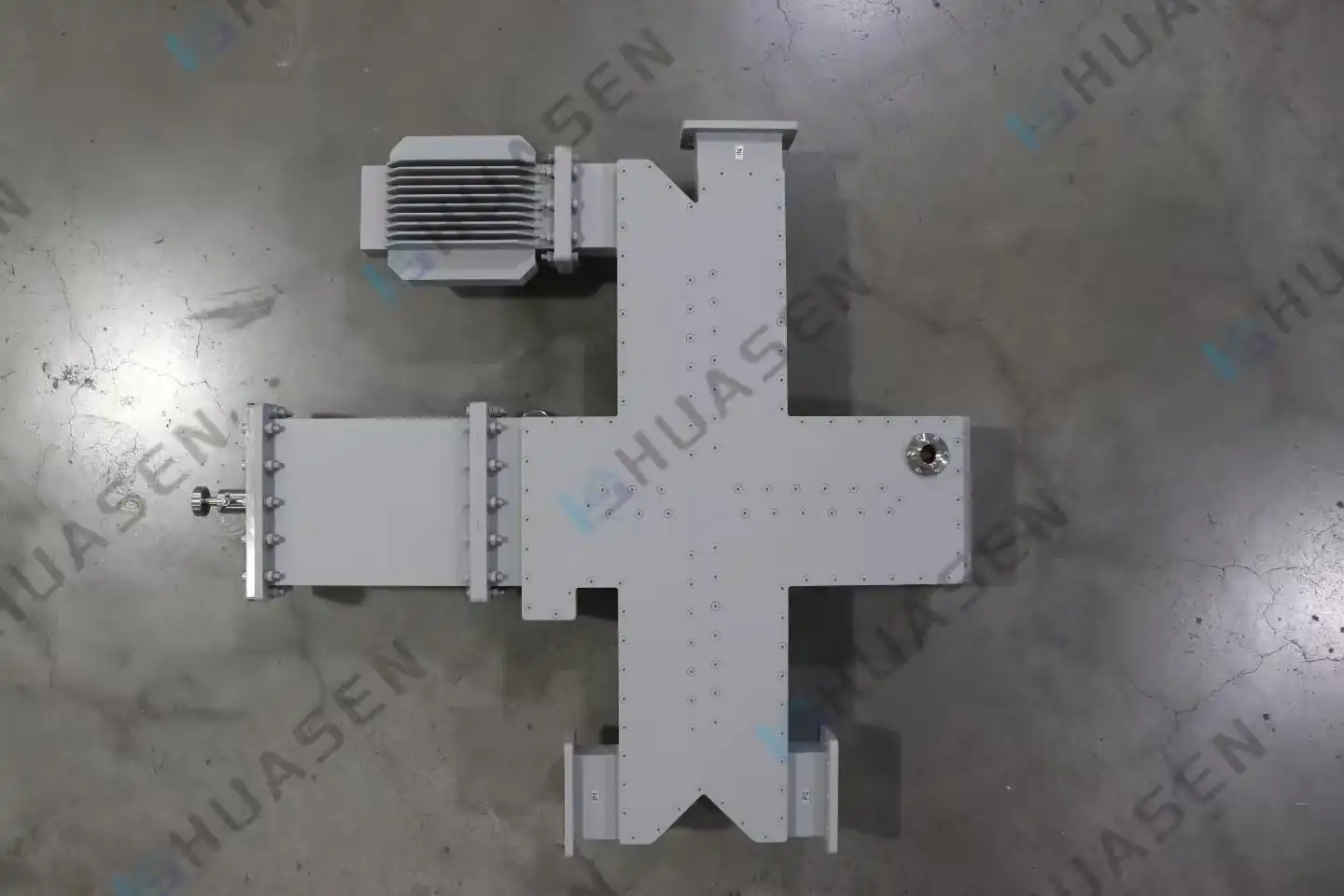
What Is a Waveguide Power Divider and How Does It Work in Radar
Selecting RF distribution components for radar systems that require high signal quality and power management is crucial. A waveguide power divider is a complex passive microwave component that splits an electromagnetic signal into two or more output pathways while maintaining amplitude and phase coherence. These hollow metallic waveguide structures operate in the TE10 mode, making them essential for high-frequency radar applications where thermal stability and minimal insertion loss affect detection range and target precision.VIEW MORE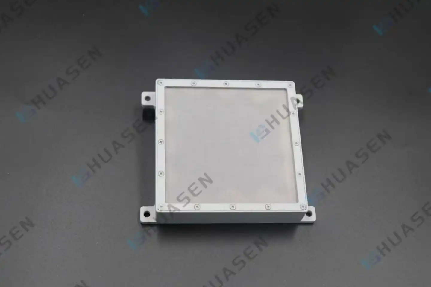
Application Scenarios for Circularly Polarized Microstrip Antenna
Circularly Polarized Microstrip Antennas are a type of planar antenna in which the electric field vector spins continuously in either a right-hand or left-hand circular pattern. This feature minimises polarisation mismatch loss, allowing signal reception independent of receiver orientation, which is important for mobile platforms and randomly oriented devices. Since reflected signals reverse polarisation and are rejected by the antenna, the method reduces multipath fading and ghosting in urban and industrial settings. These antennas solve connection dependability and signal integrity issues in complicated operational situations in high-stakes B2B businesses, including satellite communications, RFID logistics, aircraft telemetry, and 5G networks.VIEW MORE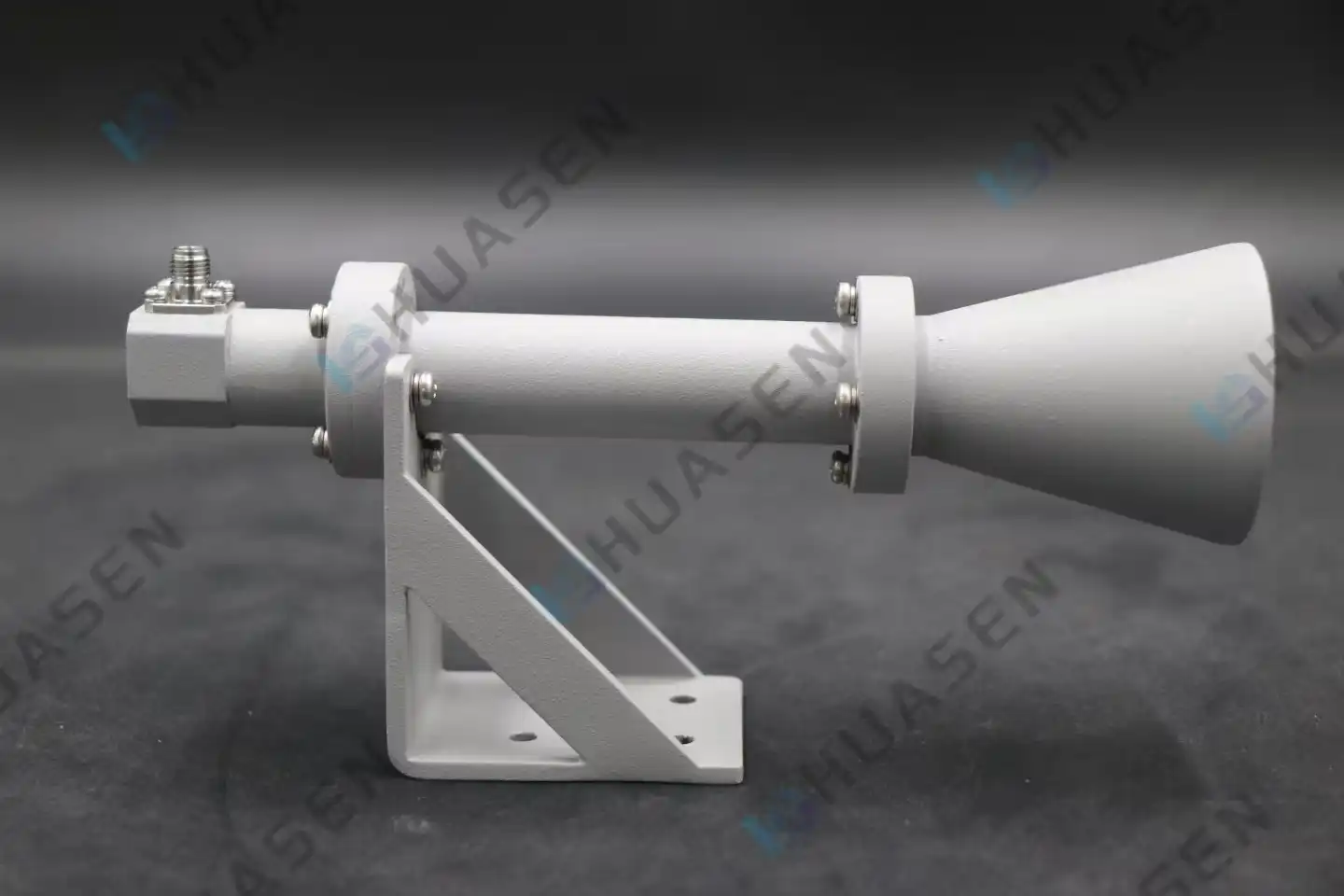
Circularly Polarized Horn Antenna Features Explained for RF Engineers
RF components like circularly polarised horn antennas are used in situations where receiver orientation or ambient multipath reflections cannot affect signal dependability. Instead of linearly polarised antennas, this technology radiates electromagnetic waves with a continuous electric field vector rotation in RHCP or LHCP, ensuring consistent performance regardless of transmitter-receiver alignment. This technology tackles significant issues in satellite communications, radar systems, and advanced wireless infrastructure, where polarisation mismatch or dynamic platform movement would decrease connection quality.VIEW MORE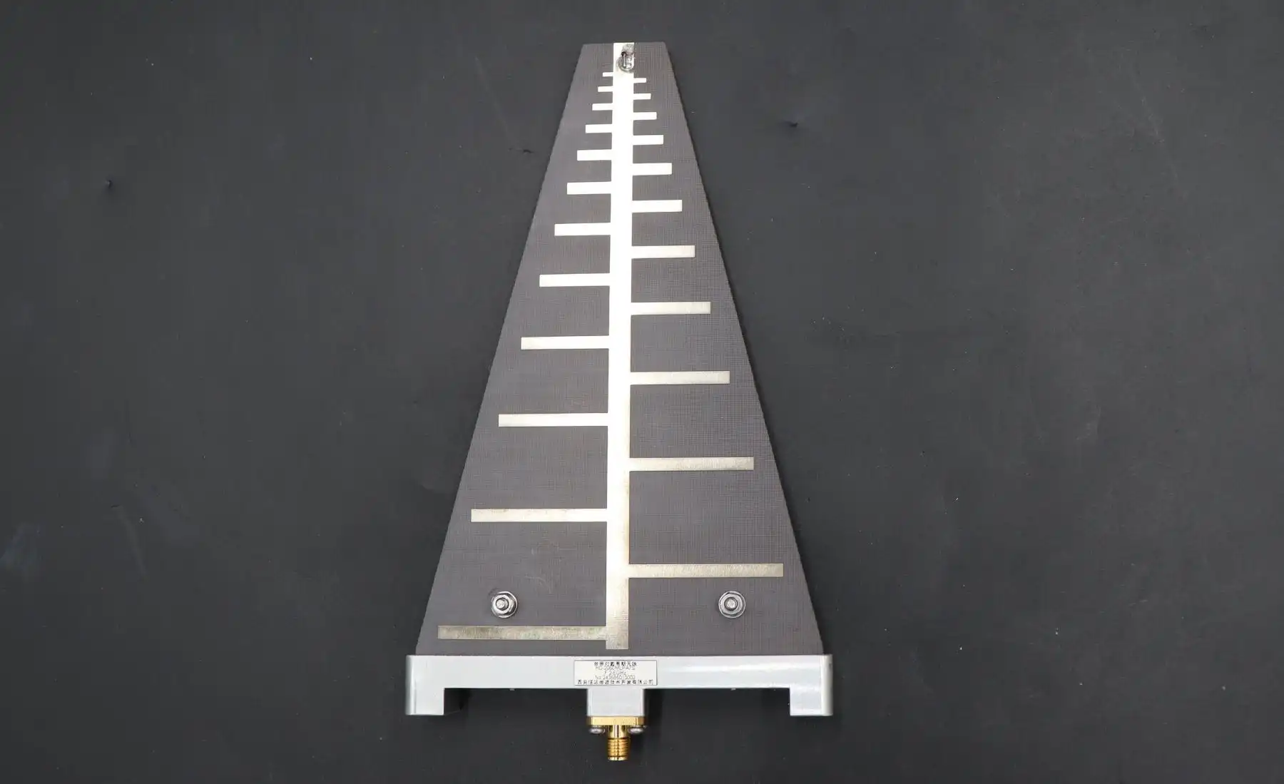
Log Periodic Antenna Construction and Element Spacing Explained
Log periodic antenna architecture uses advanced math to reduce dipole length logarithmically from the boom back to the front. Elements' location and size are regulated by two design constants: tau (τ), the scaling factor, and sigma (σ), the relative spacing ratio. This unusual design allows the antenna to retain consistent impedance and radiation across numerous octaves, making it essential for wideband RF applications where single-antenna solutions simplify system architecture and minimise operational costs.VIEW MORE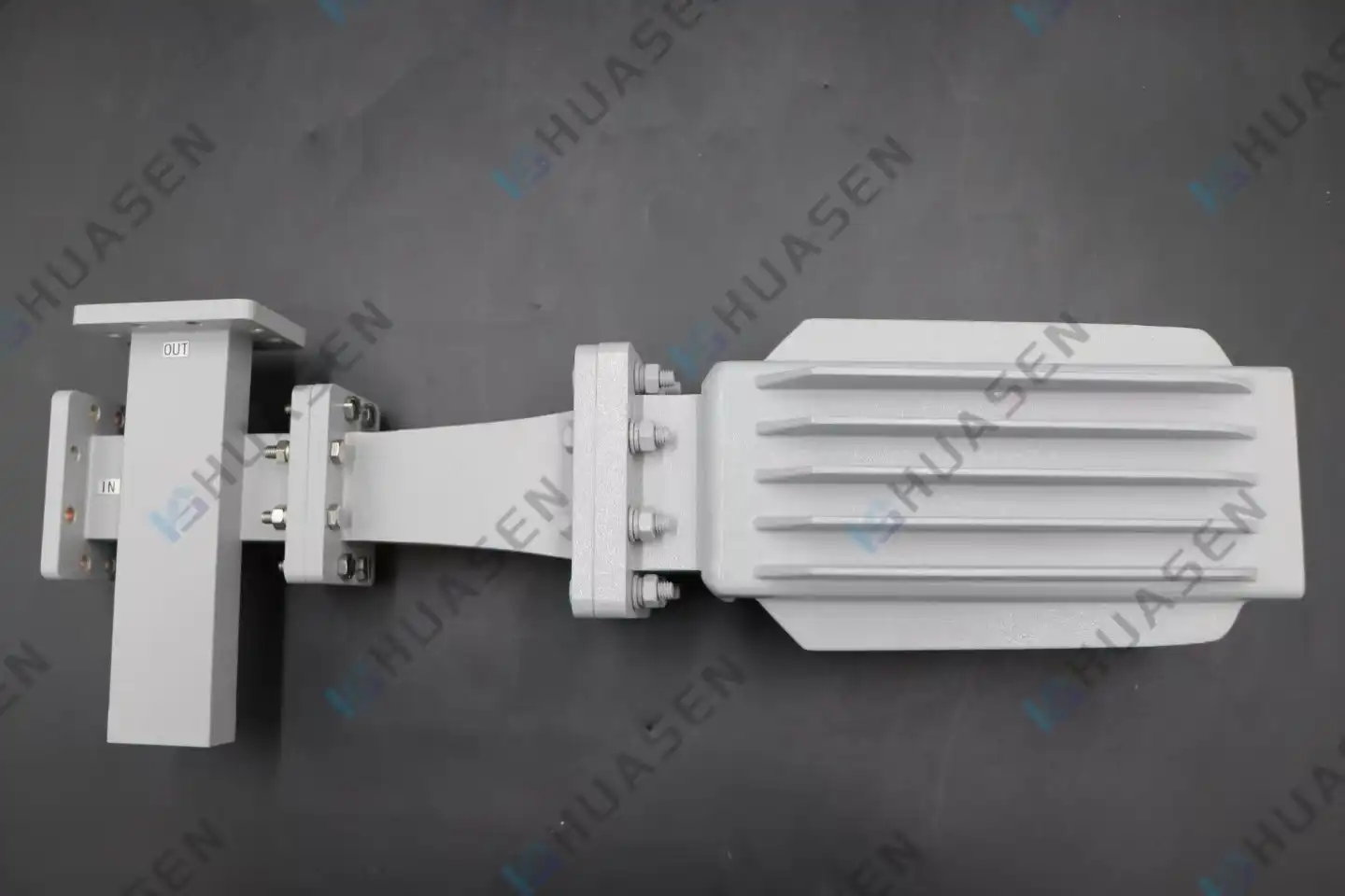
Testing Stability of Coupled Fixed Waveguide Attenuator
Testing a coupled fixed waveguide attenuator's stability is essential for signal integrity, attenuation precision, and VSWR consistency in demanding RF and microwave systems. These precision devices with high-directionality couplers and absorptive elements must perform repeatably under environmental stressors like temperature cycling, vibration, humidity, and ageing to protect 5G infrastructure, satellite communications, radar systems, and aerospace platforms. Stability testing ensures attenuation flatness, insertion loss, and phase linearity stay within specification, eliminating costly system downtime and meeting strict industry requirements.VIEW MORE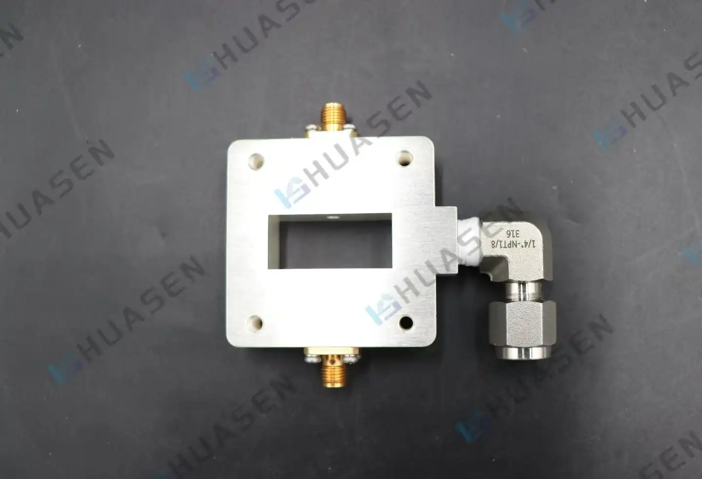
Waveguide Probe Coupler Coupling Degree Testing in Millimeter Wave Bands
Millimetre wave testing requires waveguide probe couplers to extract a tiny amount of signal power from waveguide transmission lines for monitoring and measurement. Accurate coupling degree testing is crucial at frequencies over 30 GHz, as it determines the ratio of sampled to main signal strength in decibels. Proper coupling degree testing provides system calibration accuracy, power monitoring in 5G base station frontends, and radar performance verification in aerospace applications where signal integrity is critical.VIEW MORE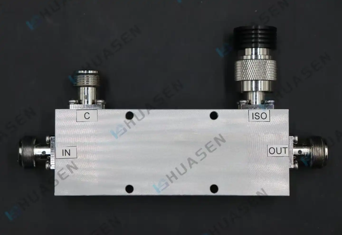
Directional Coupler vs Power Splitter: Key Differences in RF Applications
When constructing RF systems for telecommunications, radar, or satellite connections, choosing a directional coupler or power splitter affects signal integrity, monitoring, and system dependability. A directional coupler samples a percentage of electromagnetic power in a given direction while isolating it from reverse signals for real-time monitoring without disturbing the main signal route. Instead, power splitters optimise antenna array and transmitter chain signal dispersion by dividing incoming RF power equally or unequally among numerous output ports. Understanding these fundamental operating distinctions helps procurement teams choose components that meet project specifications, whether signal diagnostics or power distribution are priorities.VIEW MORE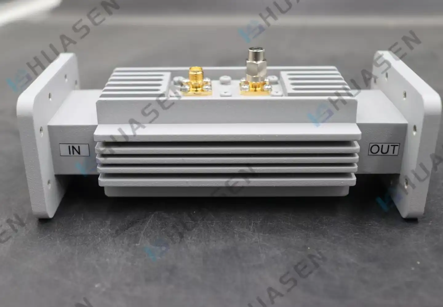
How to Select a Waveguide Loop Coupler for Radar Systems
Selection of a waveguide loop coupler for radar systems requires careful consideration of technical parameters, operating environment, and supplier capabilities. These precision-engineered passive microwave components use a magnetic loop probe to check electromagnetic power in waveguide transmission lines without affecting main line operation. Radar engineers maintain defence, aerospace, and telecommunications system dependability by prioritising coupling precision, directivity, and environmental resistance. The proper solution meets strict performance demands while balancing bandwidth, power management, and mechanical compatibility with existing waveguide infrastructure.VIEW MORE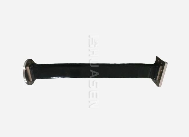
Choosing Flex Waveguide for High-Frequency Signal Routing
The proper flexible waveguide is essential for high-frequency systems that need dependable signal transmission and mechanical flexibility. Flex waveguide assemblies, precision-engineered transmission line components, solve alignment, vibration isolation, and thermal expansion difficulties in telecommunications, aerospace, radar, and satellite communication systems. These components have convoluted metallic cores—usually silver-plated brass or phosphor bronze—that allow bending and twisting without affecting RF performance. Understanding their technical specifications, application needs, and procurement concerns enables instant functioning and long-term reliability.VIEW MORE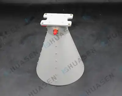
Dual Polarized Horn Antenna in OTA & EMC Testing Systems
Measurement precision can determine 5G base station, satellite ground equipment, and advanced radar system testing success. Modern OTA and EMC testing requires recording both horizontal and vertical signal components through a single aperture. Dual polarised horn antennas eliminate mechanical rotation errors and greatly reduce test cycle times. These specialised instruments are essential for laboratories, system integrators, and equipment makers who need consistent, high-fidelity measurements across several frequency bands while minimising space and operational costs. This paper covers dual-polarised horn antenna technical architecture, performance benefits, selection criteria, and sourcing methods for testing settings for procurement managers and RF engineers. Understanding these characteristics promotes informed selections that meet growing wireless standards and project needs.VIEW MORE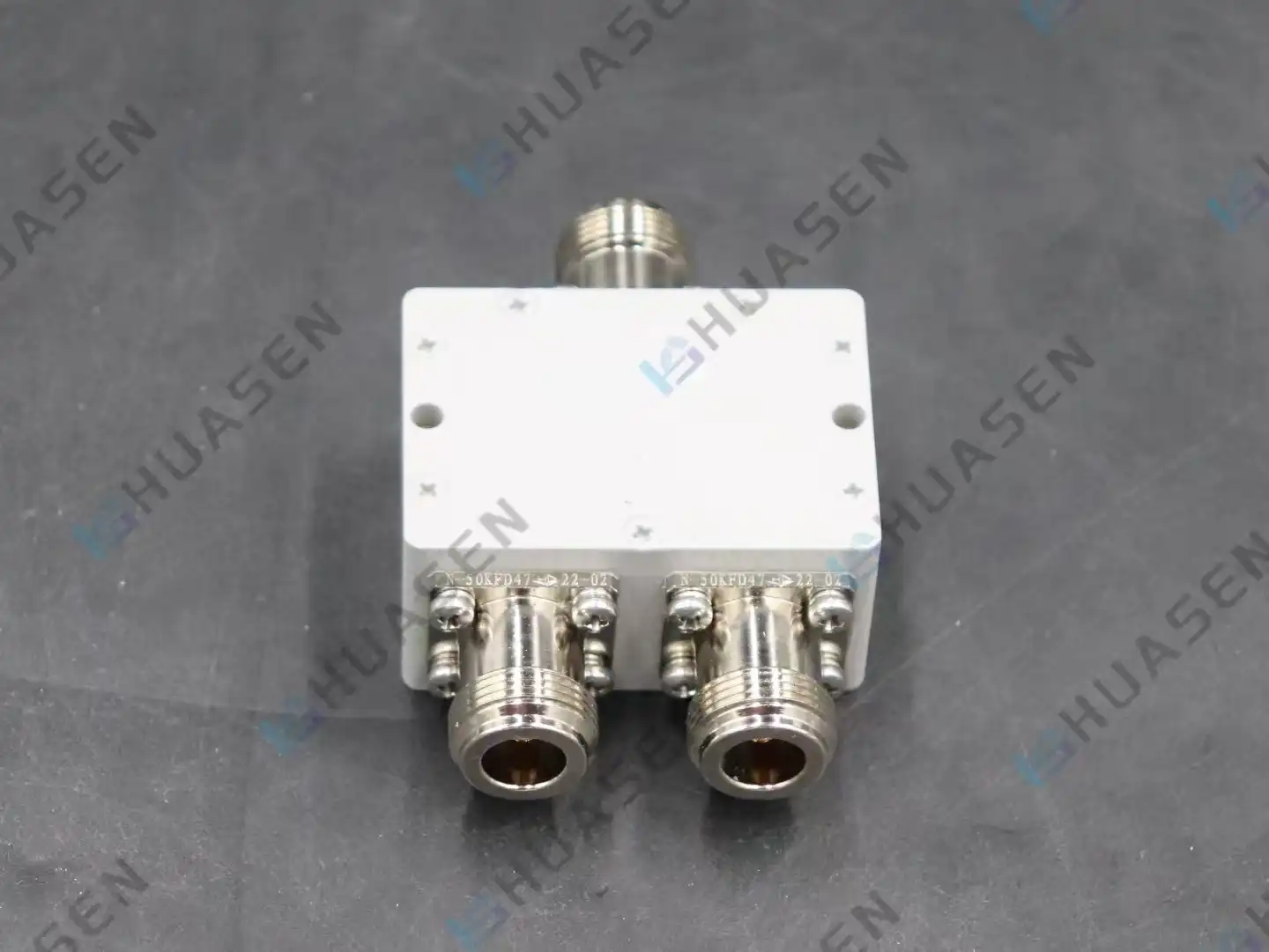
Choosing Low-IMD RF Combiners for Satellite Communication Systems
Intermodulation distortion determines satellite communication infrastructure RF combiner performance. High-power satellite ground stations and LEO constellation terminals use low-IMD RF combiners to blend numerous signal pathways while reducing undesirable mixing products that impair connection quality. These devices provide signal purity over wide bandwidths for reliable uplink and downlink performance when even modest distortion might reduce data speed or create bit errors. In harsh satellite earth station environments, electrical criteria must be balanced with mechanical endurance and thermal stability.VIEW MORE
- 1
- 16
- 17
- 18
- 19
- 20
- 60
