
Home / Blog
Blog
0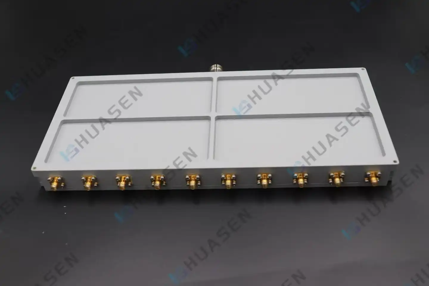
Improving Efficiency in Multi-Input Coaxial Power Combiner Systems
To make multi-input coaxial power combiner systems more efficient, you need to pay close attention to design optimisation, material choice, and strict testing methods. A coaxial power combiner is a passive RF part that takes in multiple signals and combines them into a single high-power output. It does this while keeping the signal's impedance matching and consistency over certain frequency bands. More efficiency means less insertion loss, better isolation between input ports, and better thermal management. These are all important for 5G infrastructure, satellite communications, radar systems, and aerospace platforms, where mission success depends on power handling and reliability.VIEW MORE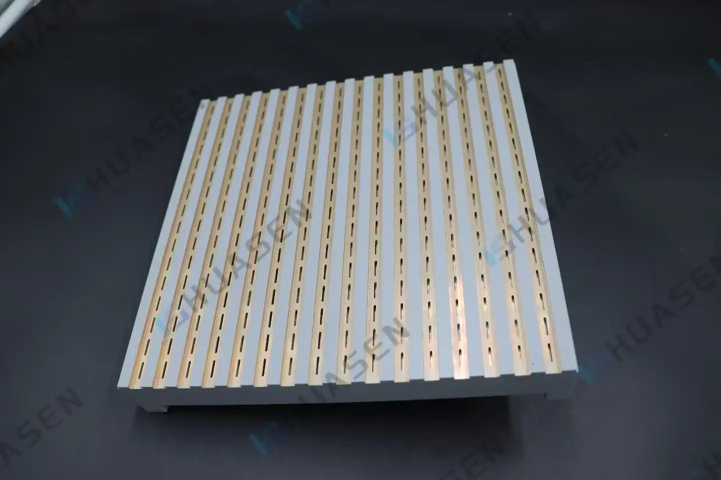
Slot Geometry Effects on Planar Slot Antenna Radiation Efficiency
How well a planar slot antenna sends out radiation depends a lot on how the slots are made—their form, size, spacing, and where they are positioned in the waveguide. Small changes in the size of a hole can move resonant frequencies, change how resistance matches, and affect how well gain works. The shape of the slots directly affects how electromagnetic waves leave the waveguide and enter empty space. If the holes are set up correctly, they cut down on surface currents that cause losses and unwanted reflections. Engineers can get higher efficiency, better bandwidth control, and better polarization uniformity across frequency bands from L-band to millimeter-wave uses by understanding these geometric effects.VIEW MORE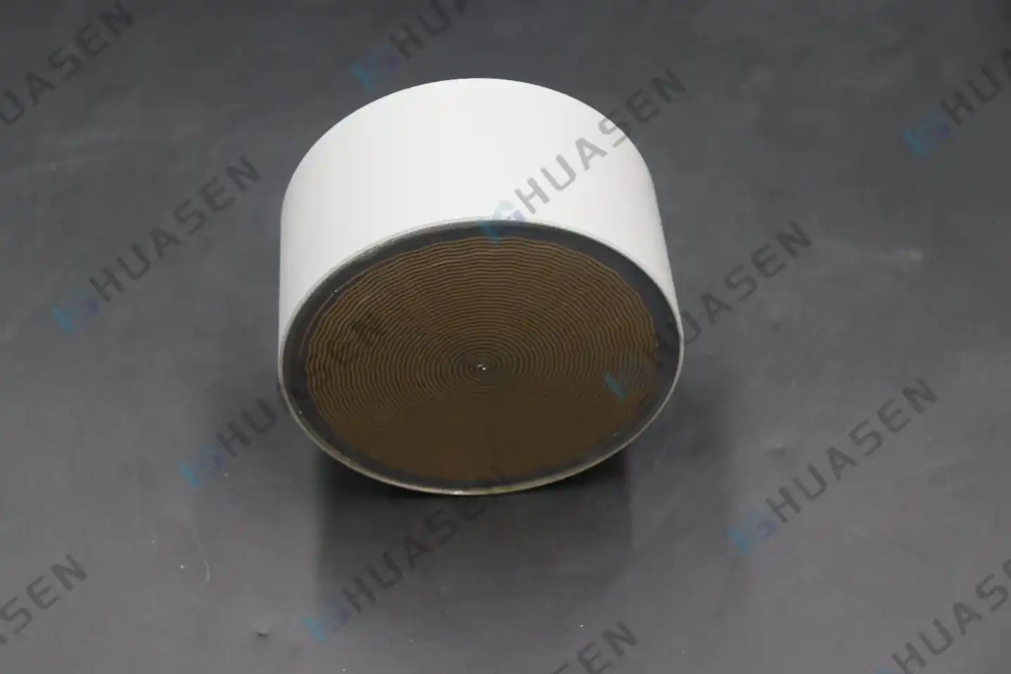
Radiation Efficiency Improvements in Planar Helical Antenna Geometry
Improving the radiation efficiency of a planar helical antenna geometry is all about finding the best structural factors to turn as much input power as possible into electromagnetic energy that is emitted. The planar helical antenna works better because the helix pitch, arm radius, number of spiral turns, and base material can all be carefully changed. These small antennas provide reliable circular polarization over very wide bandwidths, from 0.2 GHz to 18 GHz in advanced designs. They do this by using low-loss dielectrics to lower ohmic losses and impedance matching to reduce reflections. This makes them essential for electronic reconnaissance, satellite telemetry, and wideband signal monitoring.VIEW MORE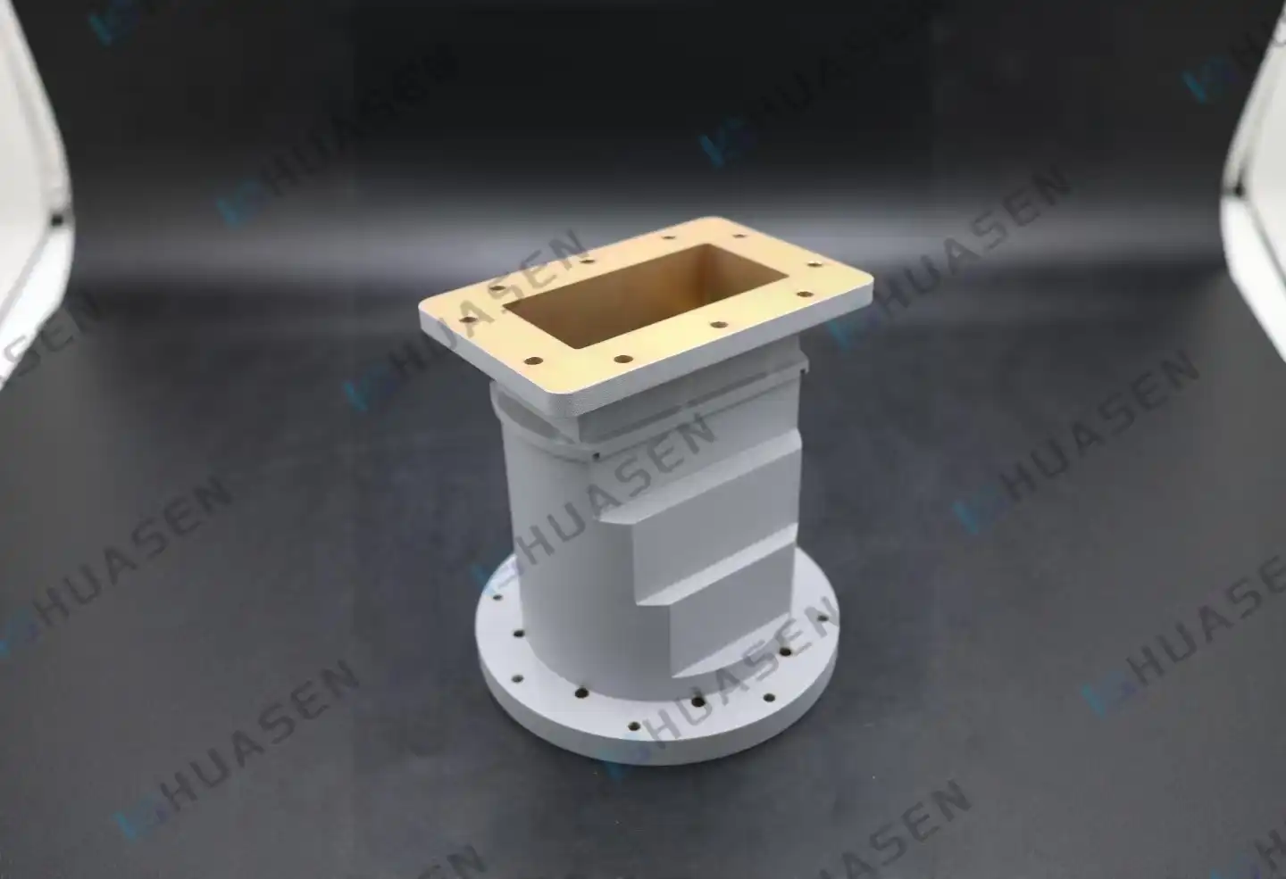
Waveguide Transition in Radar Front-End Integration Explained
When radar engineers talk about improving signal paths, they always come across the waveguide transition. This is a passive part that connects different transmission line shapes while keeping the electromagnetic integrity. It connects radio frequency energy to rectangular waveguides, coaxial connectors, or microstrip lines with very little reflection. This keeps the power and phase features of high-frequency signals as they move through X-band, Ka-band, or millimetre-wave systems. It is important for people who build, integrate, or buy parts for defence radar, satellite ground stations, or 5G backhaul infrastructure to understand how these changes work in radar front-ends.VIEW MORE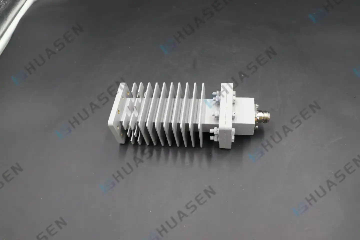
How to Select a Coaxial Fixed Attenuator for RF Systems
To choose the correct coaxial fixed attenuator for your RF system, you need to make sure that it meets your working needs as well as important electrical specs. It is very important that the resistance of your system—usually 50 ohms for radar and telecommunications—matches exactly the attenuator's design. Compatibility across a wide range of frequencies is also very important. Devices that work with frequencies from DC to 18 GHz need parts that are designed to work well across that range. Attenuation levels between 3 dB and 50 dB are used for a variety of tasks, running from small changes to the signal to big drops in power. The attenuator's power handling ability, which ranges from 1W to 500W, tells you if it can handle the energy needs of your system without breaking down due to heat. For a smooth merger, connector types like N-50J/K and SMA must work with the equipment you already have.VIEW MORE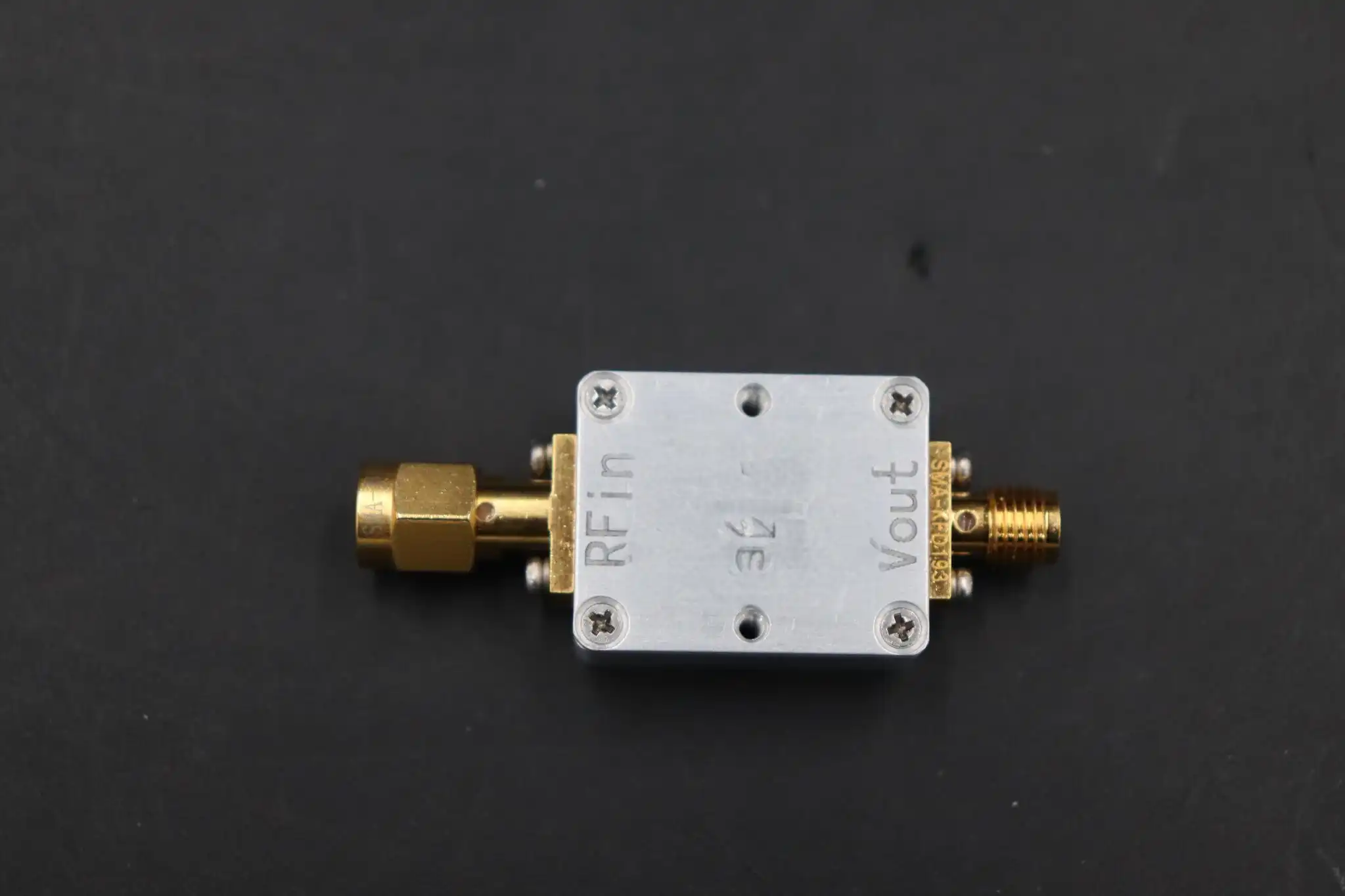
Calibration Stability Issues in Broadband Coaxial Detector Design
How stable the calibration is in a broadband coaxial detector tells you if your RF power readings stay correct over time or start to drift into mistake areas that cost a lot of money. When temperature changes, parts wearing out, or mechanical stress cause detector circuits to lose their measured reference, system engineers have to deal with measurement errors that spread through automatic level control loops, radar pulse profiling, and scalar network analysis. We need to know how diode physics, matching circuit design, and external factors affect long-term performance in mission-critical uses in order to solve these stability problems.VIEW MORE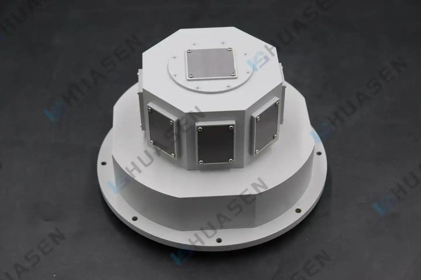
Beam Steering Accuracy in Microstrip Conformal Array Antenna Systems
In microstrip conformal array antenna devices, beam steering accuracy tells us how exactly the energy can be sent to a target. This accuracy has a direct effect on signal quality, interference suppression, and link stability in a wide range of settings, from 5G base stations to interactions in space. When conformal arrays are placed on curved surfaces, phase deviation problems arise that need to be carefully managed through compensation methods, precise manufacturing, and substrate selection in order to keep beam control tight and performance consistent across all working frequencies.VIEW MORE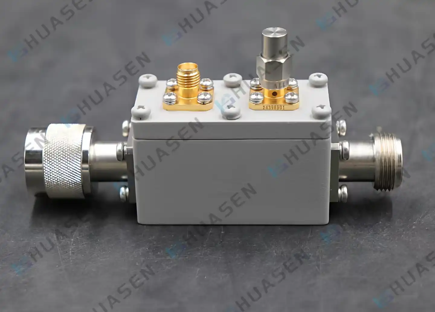
Coaxial Directional Coupler Solutions for High-Power RF Systems
Coaxial directional coupler solutions are the answer for engineering teams that need to check the security of signals in high-power RF transmission chains without blocking important routes. These inactive parts pick up electromagnetic energy moving along coaxial lines with very little insertion loss. This lets you check for forward and reflected power in real time. Their usefulness is especially clear in mission-critical applications like base station front-ends, radar receivers, and satellite communication systems that need to keep the flow of signals unbroken and measure power accurately.VIEW MORE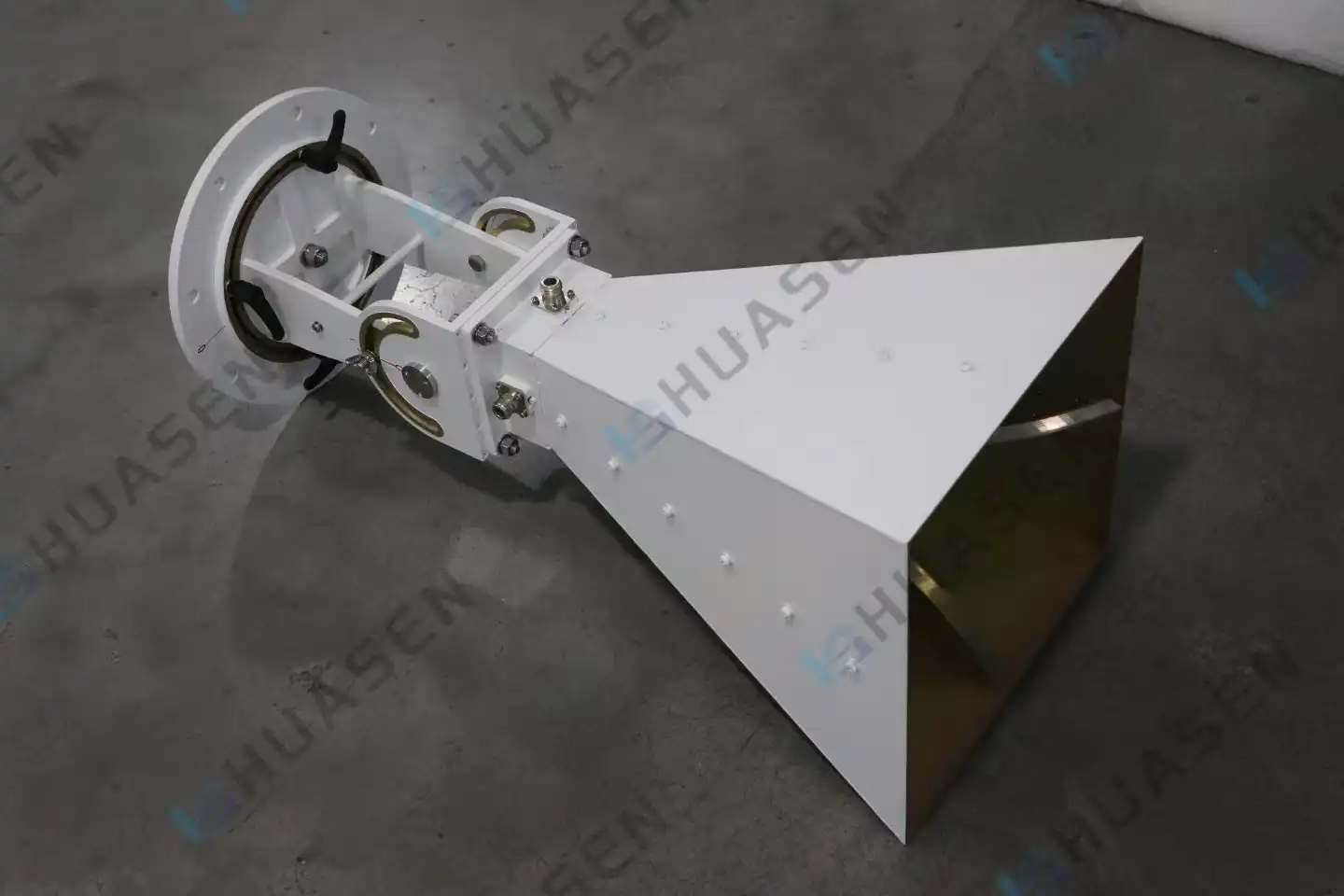
Engineering Structure Behind Quadridged Horn Antenna Bandwidth Gain
The Quad-ridged Horn Antenna's bandwidth gain comes from its four equally placed metallic ridges inside a curved waveguide. These ridges change the way impedance matching works across very wide frequency ranges. This ridge design lets it work continuously from 0.1 GHz to 40 GHz, with a stable gain range of 5 to 19 dB and excellent dual-polarization separation of more than 20 dB. The quadridged geometry solves important problems in EMC testing, radar calibration, and 5G system evaluation, where single-device multi-band coverage directly reduces capital spending and test cycle length. This is in contrast to traditional horn designs that are limited by narrow bandwidth.VIEW MORE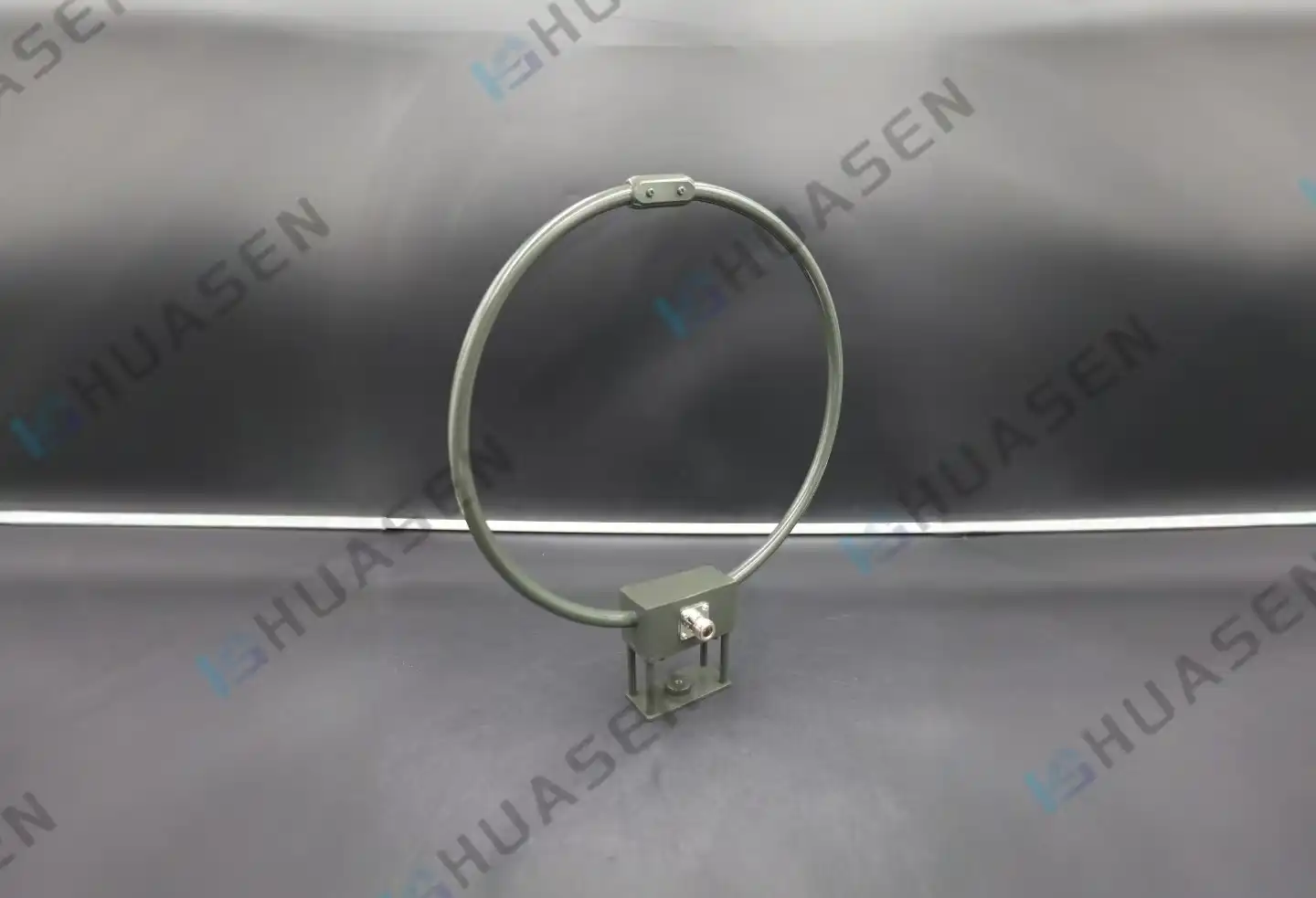
What Are the Advantages of a Loop Antenna?
Loop antennas have great noise rejection, a small design, and effective magnetic field reception. These are all features that directly solve problems in 5G infrastructure, satellite communications, radar systems, and RF testing settings. They are different from electric field antennas like dipoles because they are sensitive to magnetic fields. This lets them get better signal-to-noise ratios in places with a lot of electromagnetic interference, like cities. It doesn't matter if loop antennas are used in base station front-ends, marine communications, or EMC compliance labs; they give system designers and equipment makers flexible solutions that balance performance, space efficiency, and environmental resilience. Knowing these benefits helps people who buy things choose radio technologies that make systems more reliable and lower the total cost of ownership for tough uses.VIEW MORE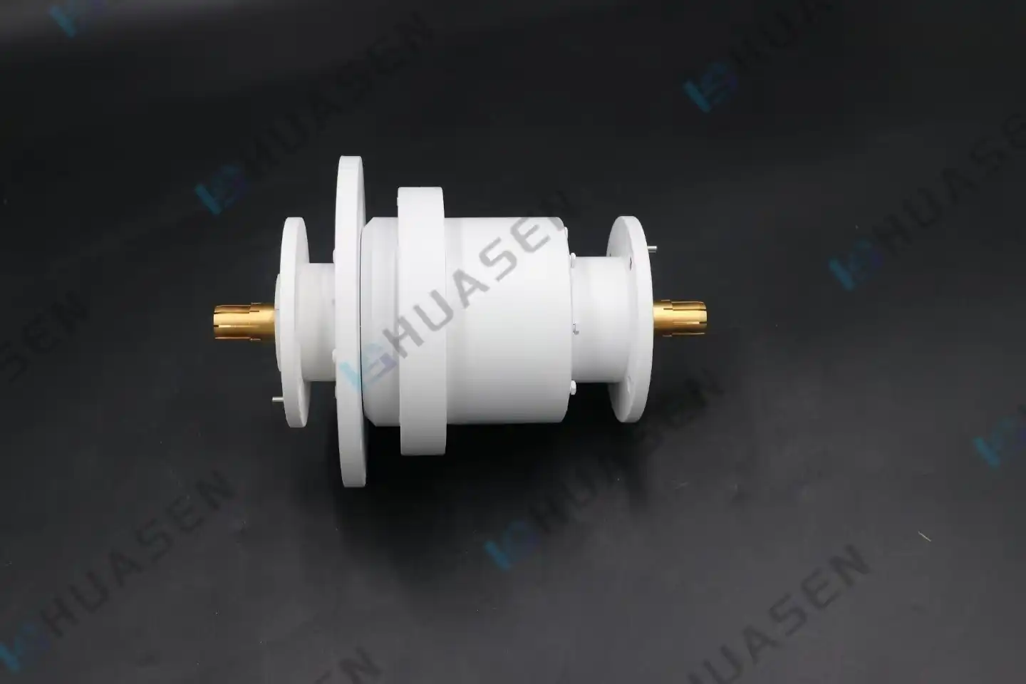
How to Select a Single Channel Coaxial Rotary Joint
Selecting the right single-channel coaxial rotary joint can make or break your RF system's performance. This specialized component maintains consistent signal transmission between stationary and rotating structures—eliminating cable twist and signal degradation in radar, satellite terminals, and test equipment. When you're dealing with frequency ranges from DC to 40GHz and power requirements that vary from milliwatts to hundreds of watts, understanding what separates an adequate rotary joint from an exceptional one becomes mission-critical. Throughout my years working with communications system integrators and radar manufacturers, I've seen how the right selection reduces downtime, improves signal fidelity, and ultimately saves engineering teams from costly redesigns.VIEW MORE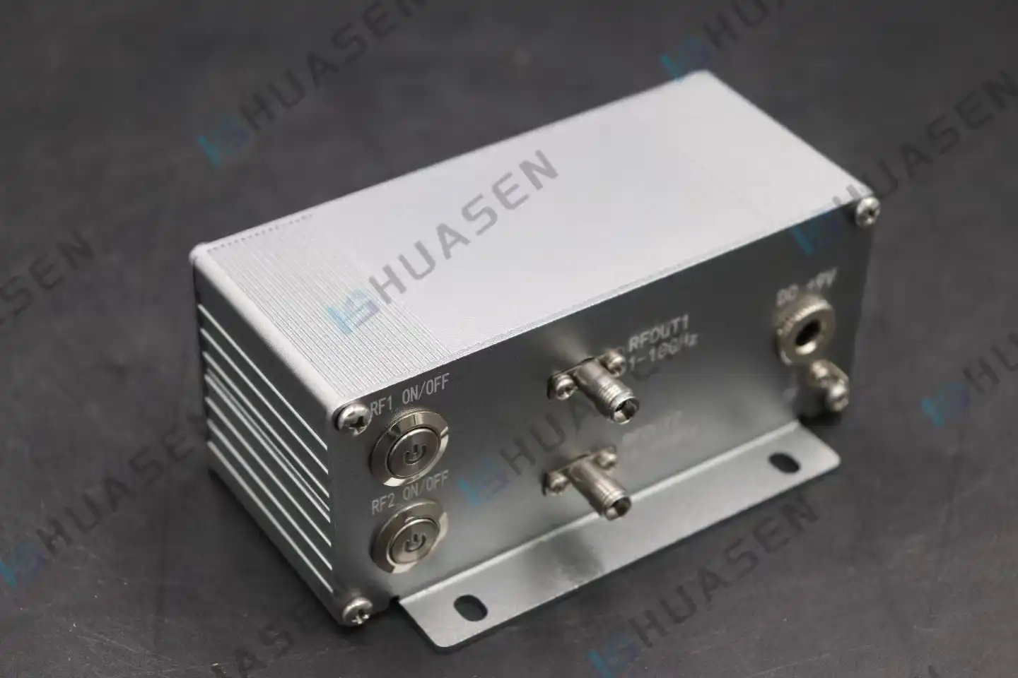
How Does a Low Noise Amplifier Improve Receiver Sensitivity?
In the first part of the receiver chain, a low-noise amplifier boosts weak RF signals while adding very little noise. This makes the receiver more sensitive. How sensitive a system is depends on how well it can find signals that are close to the noise floor. By increasing the signal level right after the antenna, the amplifier makes sure that the next parts (mixers, filters, and ADCs) receive a stronger signal compared to the noise they add. The Signal-to-Noise Ratio (SNR) stays the same throughout the system. The lower the amplifier's noise figure (NF), the lower it lowers the signal-to-noise ratio (SNR). This directly leads to better minimum signal levels and operating range.VIEW MORE
- 1
- 2
- 3
- 4
- 5
- 6
- 60
Total 60 pages
