How to Select a Coaxial Fixed Attenuator for RF Systems






2026-07-08 22:23:38
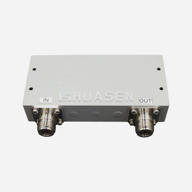
To choose the correct coaxial fixed attenuator for your RF system, you need to make sure that it meets your working needs as well as important electrical specs. It is very important that the resistance of your system—usually 50 ohms for radar and telecommunications—matches exactly the attenuator's design. Compatibility across a wide range of frequencies is also very important. Devices that work with frequencies from DC to 18 GHz need parts that are designed to work well across that range. Attenuation levels between 3 dB and 50 dB are used for a variety of tasks, running from small changes to the signal to big drops in power. The attenuator's power handling ability, which ranges from 1W to 500W, tells you if it can handle the energy needs of your system without breaking down due to heat. For a smooth merger, connector types like N-50J/K and SMA must work with the equipment you already have.
Introduction
When I work with RF engineers and procurement managers on projects for mobile communications, satellite systems, and aircraft, we always talk about one important part: the passive attenuator. These gadgets precisely control the power of signals, keeping sensitive sensors safe from overload and making sure measurements are correct in test settings. The coaxial fixed attenuator is an important part that you must have if you're making 5G base station front-ends, adjusting spectrum analyzers, or creating radar systems for UAVs.
This guide talks about real problems that system designers and equipment makers face when they need to be reliable in tough situations. We'll talk about how to look at important specs like VSWR performance, thermal stability, and connection durability while working with suppliers to meet your project's deadlines and budget. My goal is to give you useful information that will help you make better buying choices and get better system performance.
Understanding Coaxial Fixed Attenuators: Basics and Core Specifications
What Defines a Fixed Attenuator?
A fixed coaxial attenuator lowers the intensity of an RF signal by a set amount, which is recorded in decibels. Unlike changeable attenuators, these devices keep the attenuation the same no matter what changes are made outside the device. Inside the cylinder-shaped case, resistive networks set up in T-pad or Pi-pad patterns get rid of extra energy as heat while keeping the signal's purity. Because they are coaxial, these parts are very good at blocking electromagnetic interference. This makes them perfect for high-frequency uses where unwanted signals could mess up readings.
It makes sure that the source and load are properly matched. The normal impedance is 50 ohms for most RF systems and 75 ohms for cable TV uses. Reflections caused by impedance mismatch lower the quality of the signal and can even damage parts further upstream. Knowing this basic rule will help you avoid making mistakes that cost a lot of money when choosing components.
Critical Performance Parameters
VSWR tells you how well the attenuator fits the resistance of your system. Values below 1.2:1 across the working frequency range mean that there is little reflection and the most power is being transferred. When precision measurements are being made, VSWR performance has a direct effect on accuracy; even small echoes add error that grows through a series of stages.
Power grade is important to pay close attention to, especially in transmitter use. Limits on continuous wave operation are set by average power handling, while pulsed systems that are popular in radar are dealt with by peak power standards. Thin-film resistive elements on aluminum nitride surfaces work well in precise tasks up to 110 GHz, but they can only handle a small amount of power, about 1 to 2 watts. Thick-film designs on beryllium oxide surfaces can handle hundreds of watts, which means they can be used for DAS systems and power leveling at base stations.
When your system goes through big changes in temperature, the temperature coefficient of absorption becomes very important. Temperatures range from -55°C to +125°C for transmission systems used in space and outside. Attenuators of good quality keep the attenuation accuracy within ±0.5 dB at these extremes, but attenuators of lower quality drift a lot, which makes system calibration less accurate.
Fixed Versus Variable Configurations
Compared to changeable or step attenuators, fixed attenuators are more stable and reliable. Not having any mechanical adjustment devices gets rid of wear-related drift and lowers the number of failure spots. This means that upkeep costs are cheaper and calibration times are longer in automated test systems and installed infrastructure.
Variable attenuators, on the other hand, are very useful when signal adjustment is needed. These are flexible enough to be useful in labs for characterizing devices, and adaptable transmission systems use them for gain control. Knowing when each type is right for your application keeps you from over-specifying and spending money you don't need to.
Key Criteria for Selecting the Right Coaxial Fixed Attenuator
Matching System Requirements
Which coaxial fixed Attenuator families you should think about will depend on the frequency range you have. DC to 18 GHz covers most mobile communications, such as 5G millimeter-wave bands below 18 GHz, satellite L-band to Ku-band lines, and a lot of radar uses. When working with higher frequencies, like car radar at 77 GHz or Ka-band satellite communications, you'll need special millimeter-wave attenuators with 2.92mm or 2.4mm connections made for these tough jobs.
Choosing the right attenuation number strikes a balance between the need for security and the available signal power. In situations where receiver security is needed, 10 to 20 dB usually gives enough safety cushion without lowering the signal-to-noise ratio too much. It may only take 3 to 6 dB to smooth out the output of a power amplifier, but 30 to 40 dB or more are often needed to separate high-power sources from sensitive measuring equipment. Carefully figure out your system's link budget to find the best deal.
Evaluating Material Quality and Construction
In marine and outdoor settings, passivated stainless steel bodies don't rust, while salt spray and humidity quickly break down plated brass housings. The strong design can withstand at least 500 mating cycles, which is important for test equipment that needs to change connections often. Gold plating on center wires and contact areas keeps insertion loss low and protects against oxidation better than silver or nickel plating.
The quality of the building inside affects both how well the electricity works and how well the heat is managed. Precision-machined dielectric supports keep the center wire in the same place, which keeps the VSWR fixed even when the temperature or vibration changes. Thermal contact materials between the resistive elements and the case help heat escape quickly, avoiding hot spots that speed up the aging of the components.
Connector Compatibility Considerations
N-type plugs are the most common type used in high-power situations because they can handle more power and have a bigger diameter. The N-50J/K versions have gender-neutral links that make putting together the system easier. SMA connectors are small and offer great accuracy, and they can be used for precision measurement and modest power uses up to 18 GHz. When the frequency goes above 26.5 GHz, 2.92 mm, or K-connections are needed. 2.4mm connectors, on the other hand, can be used up to 50 GHz and beyond.
Make sure that the type of connection you choose works with the cables and tools that are already in place. Gender compatibility (male vs. female) stops installation mistakes and gets rid of the need for adapters that add more loss and reflection points. Specifications for torque are important. Tightening too much can damage center pins and dielectrics, while loosening too little can cause links to break. Using calibrated torque tools the way the producer tells you to greatly increases the life of connectors.
Comparative Analysis: Choosing Between Different Types and Brands
Low-Noise Versus High-Power Designs
Low-noise Coaxial Fixed Attenuators put measurement accuracy ahead of operating power. The thin-film resistive elements in these devices cause very little heat noise, which makes them perfect for measuring low-level signals, analyzing the spectrum, and checking the sensitivity of receivers. Their usual power levels of 1 to 2 watts are enough for signal analysis but not for testing transmitters or levelling power.
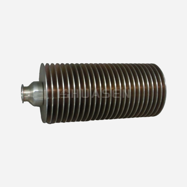
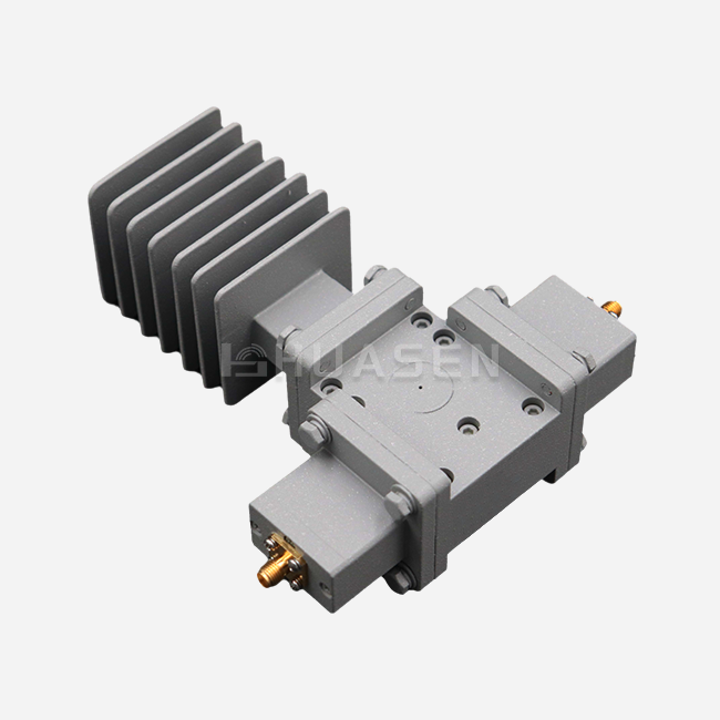
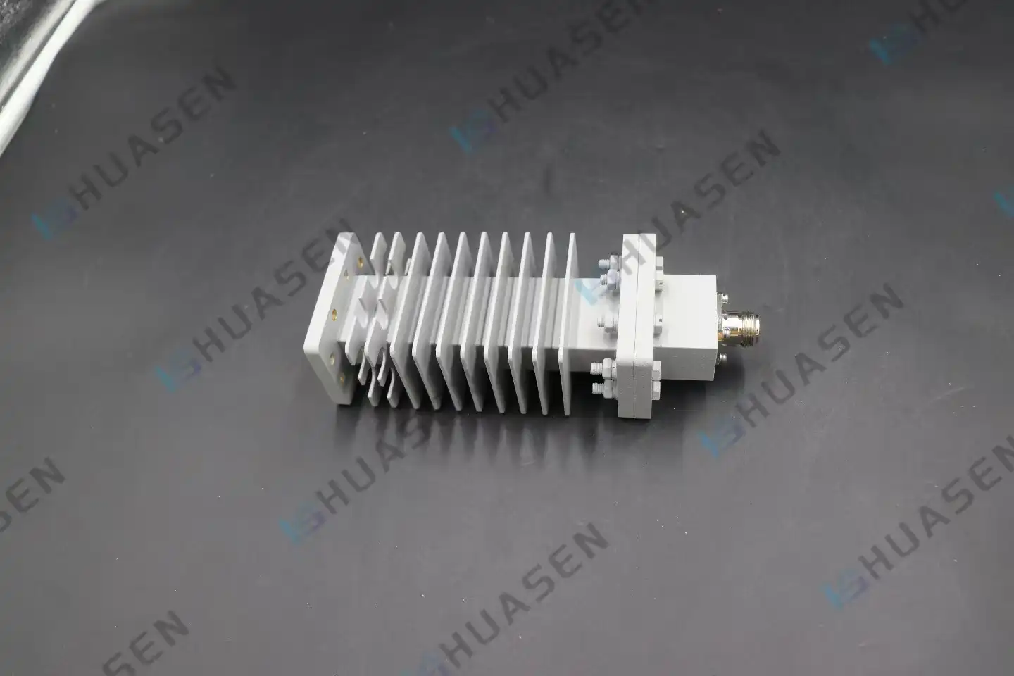
High-power attenuators use thick-film or wire-wound resistance elements that can constantly lose 50 to 500 watts of power. In base station sites where ambient temperatures are already getting close to component limits, convection cooling fans or built-in heatsinks handle the thermal loads. When compared to precision units, these tough versions don't have as good frequency flatness and VSWR performance, but they are reliable enough for high-power radar systems and outdoor phone lines.
Which of these groups you choose relies on the power profile of your program. Since test benches rarely use more than a few watts, it makes sense to use low-noise accuracy tools. Active RF chains in receivers and spread antenna systems need high power even when signal levels don't seem very strong. This is because reflections and impedance mismatches can cause short-lived power spikes that damage parts that aren't rated properly.
Manufacturer Differentiation
Well-known brands set themselves apart by using their own tools and quality control methods. Some are experts in ultra-wideband designs that keep the response flat from DC to 40 GHz. This helps companies that make test tools for a wide range of uses. Others work on toughened military-grade parts that meet MIL-DTL-3933 standards for vibration, shock, and temperature cycles, which are necessary for buying things for the military and spacecraft.
Different sellers offer very different levels of customer service. Getting help with the technical design, like system-level advice and custom setup services for a coaxial attenuator, is very helpful when working on a complicated project. When manufacturers give full calibration data and S-parameter files for every series number, it's easier to model and fix systems correctly. Production interruptions are kept to a minimum by quick after-sales help and acceptable wait times on replacement units.
Quality assurance methods tell the difference between suppliers who are trusted and those who aren't. ISO 9001 certification means basic process control, while AS9100 certification means quality management systems at the aircraft level. When companies buy things like environmental testing rooms, network analyzers, and automated production fixtures, they make sure that all of their parts meet the published specs.
Practical Guidance: Installation, Testing, and Maintenance
Installation Best Practices
The first step in a proper installation is to look at the connection ports. Check the threads for damage, the center pins to make sure they are straight, and the dielectric insulators to make sure they are still whole. Isopropyl alcohol and lint-free brushes can be used to clean the sides of connectors to get rid of dirt and dust that raises insertion loss and VSWR. Do not use rough materials on gold plating because they scratch it and speed up decay.
Tighten the connectors by hand until they are finger-tight, then use a calibrated wrench to apply the force that the maker specifies. Most of the time, 12 to 15 lb-in is needed for N-type connectors, and 7 to 10 lb-in is needed for SMA connections. When these values are exceeded, dielectrics and center pins become compressed, which forever lowers electrical performance. Under-torquing makes holes that let water in and makes links that break when the machine shakes.
Place the coaxial fixed. Attenuators in a way that makes temperature control easier when working with a lot of power. Natural airflow cooling is possible when connections are oriented horizontally and mounted vertically. Keep enough space around housings with fins to keep heat from building up. Watch the temperature of the case while it's working in high-power situations; too much heat means that the device isn't getting enough cooling or that the power level is too high.
Verification and Calibration Techniques
The most thorough way to check speed is with a network analyzer. Check the S-parameters over the whole frequency range to make sure the attenuation is correct, the VSWR is correct, and the frequency is flat. Check the recorded data against the manufacturer's specs and write down any differences that could mean damage or problems with the way the product was made. You can use measurement files to see how speed changes over time by going back and looking at them later.
Power meter testing confirms the average amount of power that can be handled in situations where controlling temperature is important. Use the maximum power and keep an eye on the temperature of the housing until thermal balance is reached. The temperature rise should stay within the limits set by the maker. For convection-cooled units, this is usually less than 100°C above room temperature. Too high of a temperature means that heat isn't being removed properly or that the resisting part is breaking down.
Troubleshooting Common Issues
Most of the time, intermittent connection issues are caused by dirty or broken plug ports. Mating cycles wear away the gold plate, revealing metals below that oxidize and make contact resistance higher. Connectors last longer if they are inspected and cleaned regularly. They need to be replaced when wear is noticeable or electrical performance drops below acceptable levels.
Unexpected changes in attenuation across frequency could mean that there is damage inside the element or that the resistance films and supports are coming apart. Thermal cycles and mechanical shock can weaken these ties, especially in lower-quality units that don't have the right adhesives. Replacement is the only option because fixing things inside is not possible, as they need to be made very precisely.
Conclusion
To choose the right coaxial fixed attenuator, you have to weigh the scientific requirements against the needs of your business and your budget. When making your choice, you should put impedance matching, frequency compatibility, power handling, and connection type in order of importance. You should also think about the surroundings and how reliable the system needs to be. Quality building materials and methods have a direct effect on how well something works in the long run, especially in tough situations where temperature changes, vibrations, or being outside are common.
It is better to buy from well-known companies with strong quality systems, good technical support, and stable supply lines than from cheaper options that don't last as long or work as well. Spending time on a full review of the source and specifications can help avoid expensive system failures and project delays later on.
FAQ
1. How Do I Determine the Required Attenuation Value?
Find the power budget for your system by testing or guessing the source's output power and comparing it to the highest amount of safety that downstream components can handle. The gap shows the lowest level of reduction that is needed. To account for changes and transients, add 3 to 6 dB of space. Check that the reduced signal levels stay above the noise floor in receiver protection applications to keep the signal-to-noise ratio at a good level.
2. Can Temperature Changes Affect Attenuator Performance?
Attenuation numbers change when resistive elements' properties depend on temperature. A good coaxial fixture Attenuator will tell you the temperature coefficient of attenuation, which is usually ±0.01 dB per degree Celsius. This is equal to a ±1 dB change over a 100°C temperature range. Tougher standards are needed for precision measurement systems, and military-grade parts with better temperature stability are the best way to keep them.
3. What Distinguishes Average Power from Peak Power Ratings?
Average power is the amount of constant wave energy that the absorber gets rid of without any damage to the heat. Peak power is the highest amount of energy that can be seen at any given time during short pulses, which are recorded in microseconds. Peak power from pulsed radar systems may be kilowatts, but normal power may only be watts because the duty cycle is so low. To avoid fails, make sure that both scores match your application.
Partner With Huasen Microwave for Superior RF Components
Huasen Microwave Technology can help you with your important RF system projects because they have more than 30 years of experience designing and making high-frequency parts. Our range of coaxial fixed attenuators covers frequencies from DC to 18 GHz, with attenuation levels from 3 to 50 dB and power handling levels from 1 to 500 watts. These ranges meet the needs of telecommunications, military, and test measurement uses. As a well-known company that makes coaxial fixed attenuators, we stick to strict quality standards during production to make sure that every part meets the stated specs and can handle harsh operational conditions.
The engineering team at our company offers full technical support, from reviewing the initial specifications to helping with fitting and improving efficiency. We offer reliable parts and quick service, whether you need standard setups delivered quickly or custom solutions made to fit your system's needs. Email our sales team at sales@huasenmicrowave.com to talk about your project needs and get full specs that are perfect for your application.
References
1. Kumar, R. & Chen, L. (2021). Precision RF Components: Design and Application Principles. Technical Press International.
2. Morrison, J. (2020). "Temperature Stability in Coaxial Attenuators for Aerospace Applications," Journal of Microwave Engineering, Vol. 45, No. 3, pp. 178-192.
3. American Institute of Electrical Engineers (2022). Standard Practices for RF Component Testing and Calibration, AIEE Publication 2022-18.
4. Zhang, W., Thompson, K., & Rodriguez, M. (2023). "Comparative Analysis of Thin-Film and Thick-Film Resistive Attenuators," International Symposium on Microwave Technology Proceedings, pp. 421-435.
5. Defense Standardization Program Office (2019). MIL-DTL-3933: Detail Specification for Attenuators, Fixed, Coaxial. Department of Defense.
6 .Patterson, S. (2022). RF System Integration: Component Selection and Performance Optimization. Cambridge Engineering Publishers.
Send Inquiry