How Does a Low Noise Amplifier Improve Receiver Sensitivity?






2026-07-06 18:45:09
In the first part of the receiver chain, a low-noise amplifier boosts weak RF signals while adding very little noise. This makes the receiver more sensitive. How sensitive a system is depends on how well it can find signals that are close to the noise floor. By increasing the signal level right after the antenna, the amplifier makes sure that the next parts (mixers, filters, and ADCs) receive a stronger signal compared to the noise they add. The Signal-to-Noise Ratio (SNR) stays the same throughout the system. The lower the amplifier's noise figure (NF), the lower it lowers the signal-to-noise ratio (SNR). This directly leads to better minimum signal levels and operating range.
Understanding Low Noise Amplifiers and Receiver Sensitivity
What Is a Low-Noise Amplifier?
An LNA is a special kind of RF part that is put at the front end of a receiver, right after the antenna and before any filters or down-conversion steps. Its main job is to boost very weak signals—often at power levels measured in picowatts—without making the noise level much higher. These devices, unlike general-purpose amplifiers, are designed to have the lowest possible noise figure. This figure shows how much noise the amplifier adds compared to the temperature noise that is already in the system.
Defining Receiver Sensitivity
Receiver sensitivity tells you the smallest signal that a system can consistently pick up and demodulate with a good error rate. It is usually given in decibels (dBm) and depends on the system noise level, bandwidth, and necessary SNR. Sensitivity = -174 dBm/Hz + 10 log(BW) + NF + SNR_required is the method engineers use to figure out sensitivity. This equation shows that the sensitivity goes down by the same amount for every decibel rise in the noise figure. Even a 0.5 dB increase in NF can add several kilometres to the range or greatly lower the amount of power needed for transmission in mission-critical applications such as satellite ground stations, radar warning devices, and 5G massive MIMO base stations.
The Signal-to-Noise Ratio Foundation
Keeping a good SNR from the radio to the digital processing is important for keeping the signal quality. If a weak signal goes into a detector without being amplified first, it might be drowned out by noise from later steps. Friis's method for the cascaded noise figure shows that the noise performance of the first stage is the best in the whole chain. By giving the input a high gain (usually 15 dB to 50 dB) and an extremely low noise figure (as low as 1.3 dB), the amplifier sets up a good signal-to-noise ratio (SNR) that later stages can't lose much of.


Core Technical Principles Behind LNAs Improving Sensitivity
Noise Figure as the Primary Metric
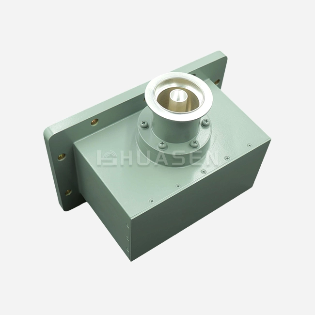
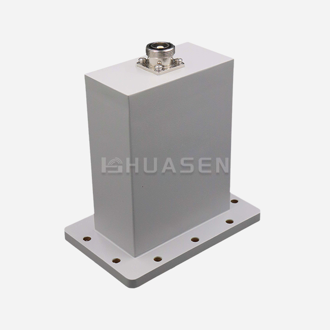
The noise figure tells you how much a working device lowers the SNR. In theory, an ideal amplifier would have an NF of 0 dB, which means it doesn't add any noise to the sound it amplifies. In real life, gadgets get numbers between 0.5 dB and 3 dB; it depends on the hardware and frequency. GaAs HEMT and InP HEMT transistors have better electron mobility at microwave and millimetre-wave frequencies, which allows them to have very low NF values. At Huasen Microwave, our devices have noise levels as low as 1.3 dB across the frequency range of 0.01 GHz to 100 GHz, which means they are very sensitive for demanding uses.
Gain and Linearity Balance
Low-Noise Amplifier. It's good to have a high gain, but too much of it can push later steps into saturation, which causes intermodulation distortion (IMD). When there are multiple signals, like in cellular base stations, linearity measures like the third-order intercept point (IP3) and the 1 dB compression point (P1dB) become very important. The best designs give you enough gain—usually 20 to 35 dB—to block out the noise from the parts that come after it without lowering the dynamic range. Maintaining linear operation stops signal degradation that would cancel out sensitivity gains when working with wideband signals that have high peak-to-average ratios.
Frequency Range and Bandwidth Selection
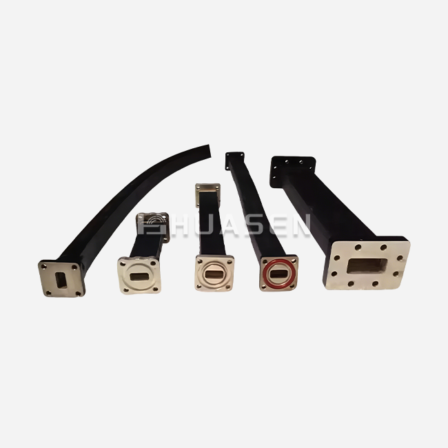
Design decisions are based on the frequency range needed for each application. Because they use resonant matching networks, narrowband systems for GPS L1 (1575 MHz) can get very low NF. On the other hand, electronic warfare ultra-wideband systems that work between 2 GHz and 18 GHz need either distributed amplifier designs or resistor feedback to keep the gain flat and the inputs matched across many octaves. We have solutions for the whole range of frequencies, from 10 MHz to 100 GHz. For uses below 6 GHz, we have N-type connectors, SMA, and K-type for microwave bands, and waveguide connections for millimetre-wave systems above 40 GHz.
Impedance Matching and Biassing
With good impedance matching, echoes are kept to a minimum (VSWR is low) and power flow is maximised. Source resistance going into the amplifier needs to be carefully managed because it has a direct effect on noise figure. Higher frequencies make it hard to match noise and power at the same time, so a balance is needed. Supply noise can't affect active devices because of stable biasing networks with low-dropout controllers and lots of bypassing. If it did, phase noise and bogus performance would get worse. Our AC line has built-in AC-DC power units that make system integration easier and keep the DC rails clean.
Comparing Low Noise Amplifiers for Different Applications
LNA Versus Other Amplifier Types
Most RF amplifiers put gain and output power first. In send chains, high-gain amplifiers may have NF values higher than 5 dB, which is fine when signal levels are already high. Preamplifiers are like LNAs in that they boost signals, but they might not be designed to have the lowest noise figure possible. 'Microwave amplifiers' is a broad term that includes a lot of different types. The main difference is that LNAs aim for very little noise addition at the cost of other factors, such as power-added efficiency or total power capability.
Application-Specific Selection Criteria
Massive MIMO systems with dozens to hundreds of receive channels are used in 5G and 6G networks. To make beamforming work, each channel needs an amplifier that has stable gain, phase, and noise. Since messages have been sent thousands of kilometres, satellite ground systems that work on the C, Ku, and Ka bands need to be very sensitive. Radar devices need boosters that can work in a wide range of temperatures and with a lot of data coming in at once. Applications in maritime and aircraft add needs for resistance to vibration, defence against humidity, and MIL-STD compliance. We can meet all of these different needs by customising things like conformal coating for harsh conditions and special connections for setups in the air.
Industry Suppliers and Selection Factors
Well-known RF LNA brands provide detailed application notes, S-parameter data, and standard designs that help speed up development. Accurate system-level models are possible with full datasheets that show how the noise figure changes with frequency, bias conditions, and temperature. When planning production runs of thousands of units, it's important to make sure the supply chain is stable. Evaluation boards make it possible to check performance without taking any risks before agreeing to large orders. As a specialised maker since 1993, we know a lot about custom frequency bands, interface needs, and qualification testing that you can't get from general catalogue parts.
Practical Procurement Considerations for LNAs
Specifications to Verify
Teams in charge of buying things should ask for sure details about things like temperature and lot output. Across the working temperature range, the noise number changes by about 0.3 dB to 0.5 dB. Gain flatness changes how the machine needs to be calibrated. Return loss changes the amount of power that bounces back towards the receiver, which could lead to interference. IP3 controls how the amplifier deals with strong sounds that aren't in the targeted band. When operating current and voltage are compatible with the power infrastructure that is already in place, costly system redesigns are avoided.
Samples and Technical Support
Asking for samples before committing to a large order lowers the risk. Bench testing can be done with standard tools thanks to evaluation boards that come with matched networks already built for 50-ohm systems. Problems with integration, such as vibration caused by bad grounding or unstable bias, can be fixed with quick expert support. Time-to-market is sped up by design help for special frequency bands or package shapes. We give you detailed test results, such as noise figure readings that can be traced back to NIST standards, S-parameters for the whole frequency range, and stability testing according to MIL-STD-883 for defence uses.
Pricing Models and Customisation Value
For small amounts of basic catalogue items, the distributor price works well. When you buy more than 100 pieces, volume pricing straight from manufacturers cuts the cost per unit by 20% to 40%. Off-the-shelf options often have flaws that can't be fixed with custom designs that are made to fit your exact frequency, gain, and input needs. With 30 years of experience in radio frequency (RF) and flexible production, Huasen Microwave is able to provide the best LNA options. Our standard series includes popular bands, and lead times are less than four weeks. Custom projects, on the other hand, usually finish in eight to twelve weeks, based on how complicated they are. Because we are quick to respond and offer reasonable pricing for both prototypes and large numbers, system designers and original equipment makers (OEMs) looking for reliable, high-performance amplification find us to be the best partner for them.
How to test and verify the performance of low-noise amplifiers?
Measurement Setup and Equipment
To measure noise figures accurately, you need special tools, such as the Keysight N9000B CXA or the Rohde & Schwarz FSW line signal analysers, which are designed to measure noise figures. The most usual way to measure output power is with the input ended in both hot (ambient) and cold (liquid nitrogen or an electronic noise source at a known temperature) loads. A measured signal source and a spectrum analyser or network analyser in transmission mode are used to measure gain. To measure IP3, linearity testing uses two-tone testing, which needs signal sources with low distortion and careful tuning.
Interpreting Results
The measured noise level (wideband LNA) should be within the range bands given in the document. Deviations can mean a number of things, such as bias point mistakes, broken input structures from ESD, or an impedance mismatch. Gaining flatness across the band shows if the matched networks are working right. In wideband digital systems, where phase uniformity affects signal integrity, group delay variation is important. Every production lot comes with a test report that shows the noise figure at three frequency points, the gain and return loss across the whole band, and the IP3 at mid-band.
Real-World Deployment Case Study
Our 3.4 GHz to 4.2 GHz wideband low-noise amplifier with a 1.5 dB noise figure and 35 dB gain was used in the ground port of a satellite communications company. The old system had a general-purpose booster with 3.2 dB NF, which made it hard to pick up weak beacon signals when it rained. The link gap got better by 1.7 dB after it was replaced, which cut down on outages during bad weather by 45%. Testing for thermal stability showed that the NF fluctuation was less than 0.4 dB from -40°C to +85°C, which met the harsh climatic needs of the remote placement site. This shows that choosing the right LNA has real benefits in practical systems.
Conclusion
Low-noise amplifiers make receivers more sensitive by creating a strong signal-to-noise ratio (SNR) at the beginning of the RF chain. These devices can pick up signals that would be lost in thermal noise because they have an extremely low noise figure and enough gain, and pay close attention to uniformity and matching. When making a choice, you have to balance technical specs with practical ones, like how the product will work in different environments and how reliable the supply chain is. Because Huasen Microwave has been focusing on RF and microwave components for 30 years, we can offer tried-and-true solutions for frequencies ranging from 10 MHz to 100 GHz, backed by thorough testing and quick support.
FAQ
1. How Does an LNA Differ from a Standard Amplifier?
Standard amps put output power, efficiency, or cost at the top of their lists. An RF low-noise amplifier especially aims for the lowest noise number while being willing to make concessions in other areas. Because they are so specialised, they are needed in receiver front ends where finding weak signals is what makes the system work.
2. Why Must LNAs Match Specific Frequency Bands?
The success of noise figures relies on input impedance matching networks that change based on frequency. Due to parasitic reactances and mismatch, a gadget that works best at 1 GHz to 2 GHz will not work as well at 10 GHz. If you choose amps that are made for the band you want to work with, you can be sure that the specs in the manual will work for your needs.
3. What Role Does Noise Figure Play in Signal Integrity?
The noise figure tells you exactly what the weaker signal is that a listener can pick up. Sensitivity goes down by the same amount for every decibel of NF. When signals have to travel long distances or face propagation losses, like in satellite links or long-range radar, reducing NF can make the operating range several tens of kilometres longer or greatly reduce the amount of power needed to send the signal.
Partner with Huasen Microwave for Superior Low Noise Amplifier Solutions
The amplification technology made by Huasen Microwave is accepted by telecommunications companies, defence contractors, and aircraft engineers all over the world. We have a wide range of products from 0.01 GHz to 100 GHz, with noise levels as low as 1.3 dB and gain levels from 15 dB to 50 dB. We can make solutions that fit your needs, whether you need N-type plugs for outdoor base stations, K-type for lab equipment, or waveguide connections for millimeter-wave systems. Our AC line with built-in power modules makes placement in faraway places easier. As a maker of Low Noise Amplifiers that can be customised, we help with the creation of prototypes all the way through high-volume production, all while keeping prices low and delivering on time. Send an email to sales@huasenmicrowave.com to talk to our technical team about your receiver sensitivity needs and to ask for test samples.
References
1. Pozar, David M. Microwave Engineering, 4th Edition. Wiley, 2011.
2. Gonzalez, Guillermo. Microwave Transistor Amplifiers: Analysis and Design, 2nd Edition. Prentice Hall, 1997.
3. Collin, Robert E. Foundations for Microwave Engineering, 2nd Edition. IEEE Press, 2001.
4. Ha, Tri T. Solid-State Microwave Amplifier Design. Krieger Publishing, 1991.
5. Vendelin, George D., et al. Microwave Circuit Design Using Linear and Nonlinear Techniques. Wiley, 2005.
6. Maas, Stephen A. Noise in Linear and Nonlinear Circuits. Artech House, 2005.
Send Inquiry