Coaxial Directional Coupler Solutions for High-Power RF Systems






2026-07-08 09:14:29
Coaxial directional coupler solutions are the answer for engineering teams that need to check the security of signals in high-power RF transmission chains without blocking important routes. These inactive parts pick up electromagnetic energy moving along coaxial lines with very little insertion loss. This lets you check for forward and reflected power in real time. Their usefulness is especially clear in mission-critical applications like base station front-ends, radar receivers, and satellite communication systems that need to keep the flow of signals unbroken and measure power accurately.
Understanding Coaxial Directional Couplers: Basics and Theory
What Defines a Directional Coupler?
A directional coupler is a precision sampling device that is built into RF communication designs. Instead of dividing power evenly like most splitters do, these parts take out a known portion of the traveling wave, usually between -10 dB and -50 dB, while keeping port isolation above 20 dB. The layout of the device uses coupled transmission line designs. Between a primary trunk and a secondary sensing line, energy moves through managed electromagnetic coupling. This physical setup lets engineers keep an eye on both the incoming and mirrored signals separately, which solves a major problem in system diagnosis.
Core Operating Principles
Instead of lumped-element behavior, the coupling process depends on interactions between electromagnetic fields that are spread out. When an RF signal travels through the mainline, a known number of pairs are sent into the auxiliary port. This is because of the physical space and dielectric properties that separate the transmission lines. Directivity, which is the measure that shows how well the coupler can tell the difference between forward and backward signals, becomes the main quality metric. Today's designs have directivity values higher than 30dB across octave bandwidths. This makes sure that measurements are accurate in VSWR analysis and automatic level control loops.
Material Selection and Power Handling
When using a lot of power, you need to pay close attention to how you handle heat and the dielectric breakdown limits. Premium couplers have housings made of precisely polished brass or aluminum that are plated with silver to reduce ohmic losses and skin effect degradation. PTFE or air-dielectric insulation keeps its electrical properties fixed at temperatures ranging from -40°C to +85°C. By increasing the cross-sections of the conductors and improving the coupling gaps, peak power ratings above 10kW are made possible. This directly meets the needs for reliability of radar and military transmission systems.
Comparison with Alternative Technologies
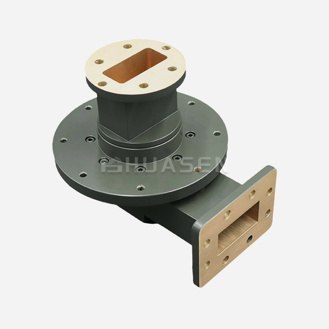
While waveguide directional couplers can handle more power, they are less compact and heavier, which are major problems for setups in spaceships and aircraft. Hybrid couplers offer quadrature phase relationships that are helpful in balanced amplifier designs, but they don't have the wideband performance that is needed for tracking base stations across multiple bands. Circulators provide great separation, but they cost more and have more insertion loss. Because of these trade-offs, coaxial directional couplers are the best way to balance performance, size limitations, and cost-effectiveness in the aircraft and telecom industries.
Key Performance Metrics and Their Impact on High-Power RF Systems
Directivity and Measurement Accuracy
The coupler's ability to split incident and reflected power components is measured by its directivity. When the value is less than 20 dB, the linked port accidentally picks up signals that are traveling in the opposite direction. In 5G massive MIMO systems, antenna mismatch detection saves costly power amplifiers. Directivity requirements above 25 dB across GHz bands make sure operators get useful fault data instead of confusing readings. To get calibration errors of less than 0.3dB, testing labs that do return loss verification need directivity of more than 30dB.
Insertion Loss Considerations
Every decibel of insertion loss directly lowers the efficiency of the sender and makes the wireless network's service area smaller. Because they use low-loss dielectrics and optimized wire shapes, premium coaxial directional couplers keep mainline losses below 0.3 dB. When added to 500W base station amplifiers, this standard saves more than 35W of power compared to poor designs that lose 0.8 dB. This difference adds up over thousands of cell sites, affecting both running costs and the difficulty of managing heat.
VSWR and Impedance Matching
Low VSWR values—ideally less than 1.20:1 across the working bandwidth—make sure that the coupler works without being seen in the RF chain. When VSWR is high, it creates standing waves that mess up readings from coupled ports and set off false alarms in safety circuits. When satellite transmission uplinks are close to amplifier saturation, they can't handle changes in impedance that would make link gaps smaller. Manufacturers use vector network analyzer evaluation at room temperature and at high and low temperatures to make sure that the VSWR is correct in environments ranging from -55°C to +125°C.
Frequency Range and Bandwidth Trade-offs
Wideband couplers that work with frequencies between 0.03 GHz and 40 GHz can be used with software-defined radios and test equipment that needs to be able to measure over multiple octaves. As a compromise, these designs are okay with slightly less flat directivity (±2dB change). Narrowband versions that are optimized for certain bands, like 5.8GHz ISM or 28GHz 5G millimeter wave, have better directivity (>28dB) and tighter coupling tolerance (±0.5dB) thanks to structures that improve resonance. To avoid spending for spectral coverage that isn't needed, procurement teams need to make sure that the bandwidth choices they make match up with the real system tuning ranges.
Selecting the Best Coaxial Directional Coupler for Your Applications
Evaluating Technical Specifications
To choose the right components, you must first match the needs of the application with the factors listed in the document. To keep the detector voltage steady when the temperature changes, a radar's automatic gain control loop needs a tight coupling range of no more than 0.75dB. For maritime satellite ports to work with salt spray, they need to be sealed with IP67 and have links that don't rust. Base station processors aim for low passive intermodulation levels below -160 dBc to keep in-band interference from lowering spectral efficiency. Making a needs matrix that ranks these factors by how important they are to the business makes comparing vendors easier.
Supplier Capabilities and Support
Established makers set themselves apart by being open about all of their test data and offering quick engineering help. Reliable brands offer full S-parameter files that can be used with modeling tools. This lets system designers guess how the cascade will work before putting together the prototype. Having access to pre-production samples lets you test them in real-world settings, which lowers the risk of release. Full-service providers are different from catalog-only wholesalers because they can customize things like coupling values, ruggedized housings, and non-standard connector combos.
Lead Times and Supply Chain Considerations
Standard catalogue items usually ship within two weeks, but custom designs can take up to eight weeks, based on how hard they are to make. Setting up framework deals that ensure component availability and lock prices for yearly amounts is helpful for large system designers who are in charge of production plans. Minimum order numbers should match the needs of the project phase. These can range from a single unit for a sample to 100 or more pieces for a production run. Knowing about these details can help you avoid costly program delays when moving from design validation to full-scale production.
Practical Applications and Case Studies in High-Power RF Systems
Power Monitoring in 5G Base Stations
These days, huge MIMO base stations have groups of 64 or more antenna elements, and each one is powered by its own power amplifier that puts out an average of 10W. Each broadcast chain has directional couplers that measure forward power for digital pre-distortion methods and reflected power for VSWR safety circuits. A big telecom company put in place bidirectional couplers with -30 dB coupling across 3.3–3.8 GHz. This let their remote monitoring tool find antenna failures within 100 milliseconds, which kept amplifiers from getting damaged and kept service interruptions to a minimum. The protected designs worked well on rooftops in the Arizona desert, in the Canadian winter, and in other places for five years without losing any performance.
Radar Transmitter Feedback Loops
For reliable transmit/receive switch timing calibration, a military contractor working on X-band phased-array radar needed Coaxial directional couplers that could handle 2 kW of peak power and have directivity greater than 28 dB. Standard catalog items had too much insertion loss (0.6 dB), which cut the detecting range by 8%. Working together with the engineering team, a special high-power version was made with bigger connection structures and better heat absorption. It has a 0.25dB insertion loss and meets all electrical requirements. By making these changes, the radar was able to meet range standards without having to buy more expensive boosters.
Laboratory Test Equipment Integration
When characterizing high-power amplifiers across 6–18 GHz, a defense contractor's microwave component test lab had trouble with repeatable measurements. They already had broadband couplers that had directivity roll-off below 18dB at band edges. This made measures of return loss unclear to within 1.2dB. When precision couplers with >25dB directivity across the full bandwidth were added, measurement confidence intervals got better to ±0.4dB. This let the team prove beyond a reasonable doubt that the specifications were met. Better accuracy got rid of the need for expensive amplifier remake cycles that were caused by test data that wasn't accurate.
Procurement and Ordering Guide for Coaxial Directional Couplers
Product Series Overview
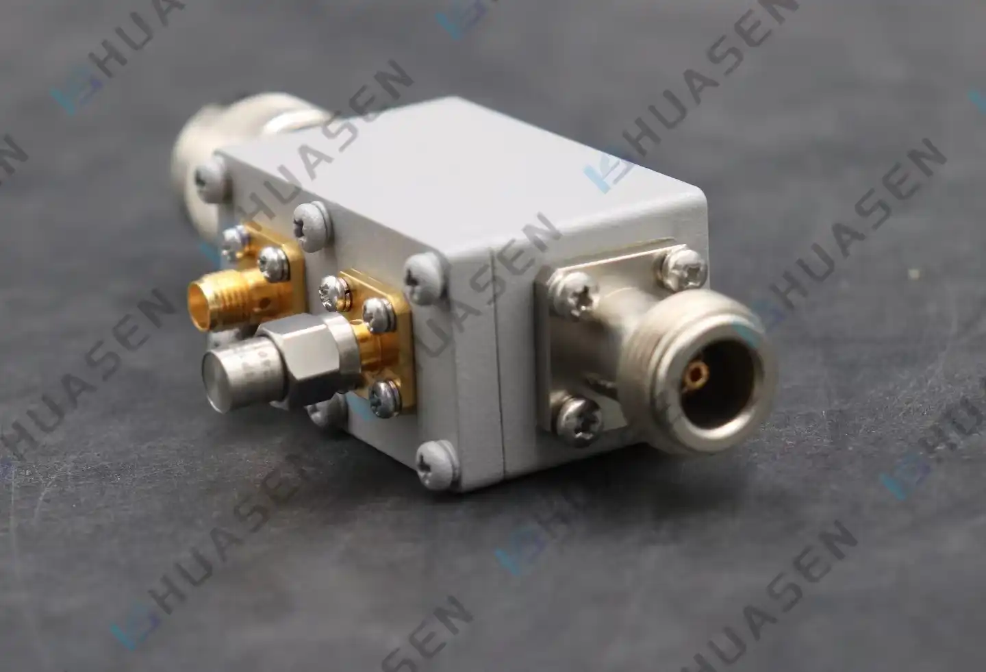
We have three main coupler types that each meet a different set of application needs. Standard Type (CC) types are good for general tracking tasks and have coupling values between -10dB and -50dB. They cover frequency ranges from 30MHz to 6GHz and come with N-type, SMA, and 2.92mm interfaces, among others. High Power Type (CHPC) couplers can handle constant average power levels of up to 500W. This makes them ideal for broadcast transmitters and industrial RF heating systems that need to handle a lot of power while keeping directivity above 23dB. Bidirectional Type (CDC) designs have two coupled ports that watch forward and backward power at the same time. This gets rid of the need for two coupler installations in VSWR measurement systems and feedback control applications.
With hermetic connection seals and conformal-coated circuit boards, these devices are fully protected and will work reliably in outdoor base stations and marine settings. The frequency range for the whole product line goes from 0.03 GHz to 40 GHz, so it can be used for everything from high-frequency transmission to Ka-band satellite links. Coupler accuracy requirements of ±0.75dB and VSWR levels below 1.25:1 give calibration labs and system programmers the measuring trust they need.
Understanding Pricing and Lead Times
Catalogue prices are based on levels of volume, with 30% more expensive single-unit sample sales compared to 50-piece production orders. Standard setups from our CC series ship within 10 business days, but CHPC high-power versions take 15–20 days because they need to be tested in a special way. Depending on how complicated the engineering is, custom specs like changed coupling values, different connector types, or higher temperature levels can add 4 to 6 weeks to delivery times.
To get formal quotes for a coaxial directional coupler, you need to give information about the goal frequency range, coupling value, power handling needs, preferred connectors, and the number of items you expect to buy. Our sales experts compare these specs to designs that are already on the market and then suggest the best options that might be cheaper by making small changes to the parameters. Sample evaluation programs let qualified buyers test parts in real-world settings before making large purchases, which greatly lowers the risk of deployment.
Conclusion
Coaxial directional couplers are very important for finding problems in high-power RF systems used in defense, aircraft, and telecommunications. Because they can sample signal power without interfering and keep low insertion loss and high directivity, they can monitor systems in real time, which saves expensive amplifiers and ensures transmission quality. To choose the right component, you have to balance technical specs like coupling factor, directivity, power handling, and frequency coverage with practical buying factors like source trustworthiness, customization options, and delivery times. By knowing these factors and how they affect operations, engineering teams can come up with solutions that improve both the performance of the system and its cost over its lifetime.
FAQ
1. What frequency ranges do standard coaxial couplers cover?
Standard catalog options usually cover 30MHz to 40GHz, with types that work best with popular bands like VHF/UHF, cellular frequencies (700MHz–6GHz), X-band radar (8–12GHz), and millimeter-wave 5G (24–40GHz). When compared to narrowband designs made for specific tasks, wideband designs that cover many octaves lose some of their directivity performance.
2. How do I determine required directivity levels?
Directivity must be higher than 25dB for applications that need accurate measures of reflected power, like VSWR safety circuits and antenna diagnostics. Because they react to changes in relative power rather than exact readings, automatic level control loops can handle lower directivity (20dB at most). When setting this parameter, look at measuring error budgets for coaxial directional couplers.
3. Can couplers be customized for unique power requirements?
Standard designs are often changed by manufacturers to fit different power levels, connection values, or weather conditions. When someone asks for customization, they should include specifics about the average and peak power, job cycle, working temperature range, and environmental exposure. Engineering teams check to see if the change is possible and give lead time predictions based on how complicated the change is.
Partner with Huasen Microwave for Reliable RF Solutions
Since 1993, Huasen Microwave Technology has been a reliable seller of coaxial directional couplers to the aircraft, telecommunications, and defense industries around the world. Our engineering team works directly with system developers to come up with the best coupling solutions, ranging from standard monitoring uses to special high-power versions that can handle 500W of continuous operation. Our coupler product lines meet the tough needs of 5G infrastructure, phased array radar, and satellite communication systems. They work reliably in sealed outdoor sites and cover a wide frequency range, from 30 MHz to 40 GHz.
We encourage people who work in sourcing and engineering to talk to our technology specialists about application-specific needs. You can ask for sample evaluation units to make sure they work well in your real-world settings, or you can email our sales team at sales@huasenmicrowave.com to get full datasheets, pricing information, and delivery dates. Huasen Microwave provides the quality, support, and supply chain stability that mission-critical RF systems need, whether you need a single sample or more than 500 units in production.
References
1. Pozar, David M. Microwave Engineering, 4th Edition. Wiley, 2011.
2. Rizzi, Peter A. Microwave Engineering: Passive Circuits. Prentice Hall, 1988.
3. Collin, Robert E. Foundations for Microwave Engineering, 2nd Edition. Wiley-IEEE Press, 2001.
4. Kumar, Annapurna and Himed, Braham. Principles of Waveform Diversity and Design. SciTech Publishing, 2011.
5. Vendelin, George D., Pavio, Anthony M., and Rohde, Ulrich L. Microwave Circuit Design Using Linear and Nonlinear Techniques, 2nd Edition. Wiley-Interscience, 2005.
6. Hickman, Ian. Practical RF Handbook, 4th Edition. Newnes, 2006.
Send Inquiry