Waveguide Transition in Radar Front-End Integration Explained






2026-07-08 22:23:39
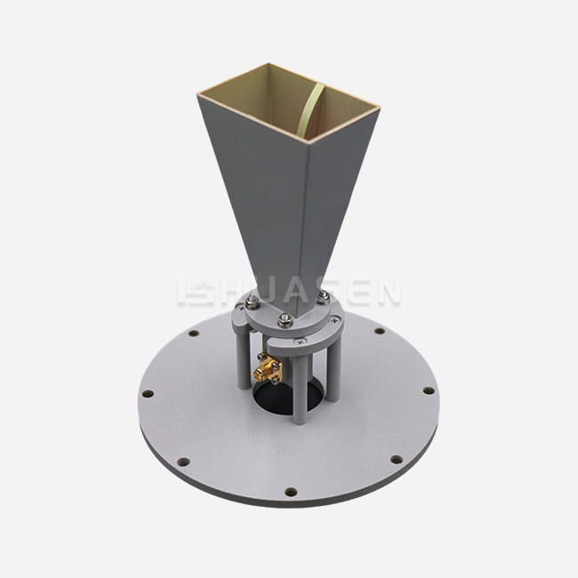
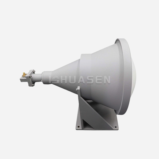
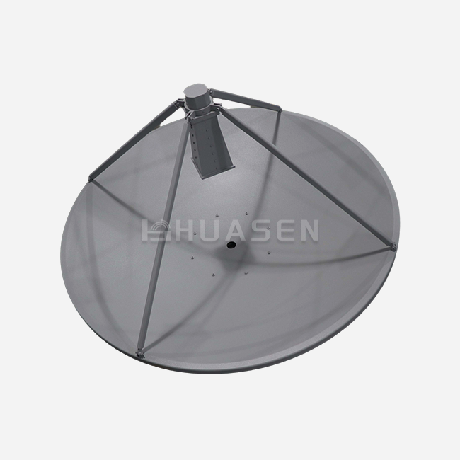
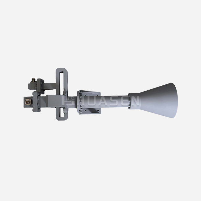
When radar engineers talk about improving signal paths, they always come across the waveguide transition. This is a passive part that connects different transmission line shapes while keeping the electromagnetic integrity. It connects radio frequency energy to rectangular waveguides, coaxial connectors, or microstrip lines with very little reflection. This keeps the power and phase features of high-frequency signals as they move through X-band, Ka-band, or millimetre-wave systems. It is important for people who build, integrate, or buy parts for defence radar, satellite ground stations, or 5G backhaul infrastructure to understand how these changes work in radar front-ends.
Understanding Waveguide Transitions and Their Role in Radar Front-End Integration
What Makes a Waveguide Transition Essential?
For radar front-ends to work, amplifiers, filters, antennas, and test tools must all be able to join without any problems, even if they use different communication standards. The geometry mismatch problem is fixed by a waveguide transition, which changes one cross-sectional shape into another slowly. When you connect a WR-90 waveguide flange to a WR-112 section or a coaxial SMA connection to a rectangular waveguide, these parts keep the impedance from dropping suddenly, which would send power back to the emitter.
The science behind these gadgets is based on changing resistance. Engineers make internal structures that are tapered or stepped so that the characteristic resistance of both ends is the same. This is similar to how an audio horn matches air to a speaker diaphragm. If you don't match the voltage standing wave ratio correctly, it goes up. This can cause power loss, signal distortion, and even damage to sensitive solid-state amplifiers.
Electromagnetic Properties and Signal Integrity
To keep the signal pure during a shift, unwanted higher-order transmission modes must be stopped. If the adapter isn't made well, it could change the main TE10 mode in a rectangular waveguide into parasitic modes that take energy away from the signal route. Maintaining mode purity is very important in radar applications where finding targets accurately relies on clean spectral content and low phase noise.
These changes are needed for radar systems that work between 8 GHz and 110 GHz to connect to spinning joints, ferrite circulators, and phase shifters. These seemingly simple parts are used in military fire-control radars, weather monitoring systems, and car collision-avoidance sensors. They have to work reliably in a range of temperatures and vibration levels that are defined in MIL-STD-810 outdoor testing procedures.
Design Considerations for Minimising Loss
One of the most closely looked at factors in transition selection is insertion loss. The signal-to-noise ratio goes down with even 0.3 dB more loss in a receiver chain, which limits the range of detection. Engineers who want low-loss performance ask for changes with smooth internal shapes, precision-machined flanges, and surface treatments that increase conductivity.
The choice of material has a direct effect on efficiency. Oxygen-free copper is a good conductor but heavier, so it can be used for radar sites on the ground. Aluminium alloys are lighter than copper by 65%, which makes them better for radar pods in the air and instruments on UAVs, where every gramme counts when it comes to flight time. Putting silver or gold on the surface stops rusting, which would raise resistance losses over time. This is especially important in coastal areas where salt spray is present.
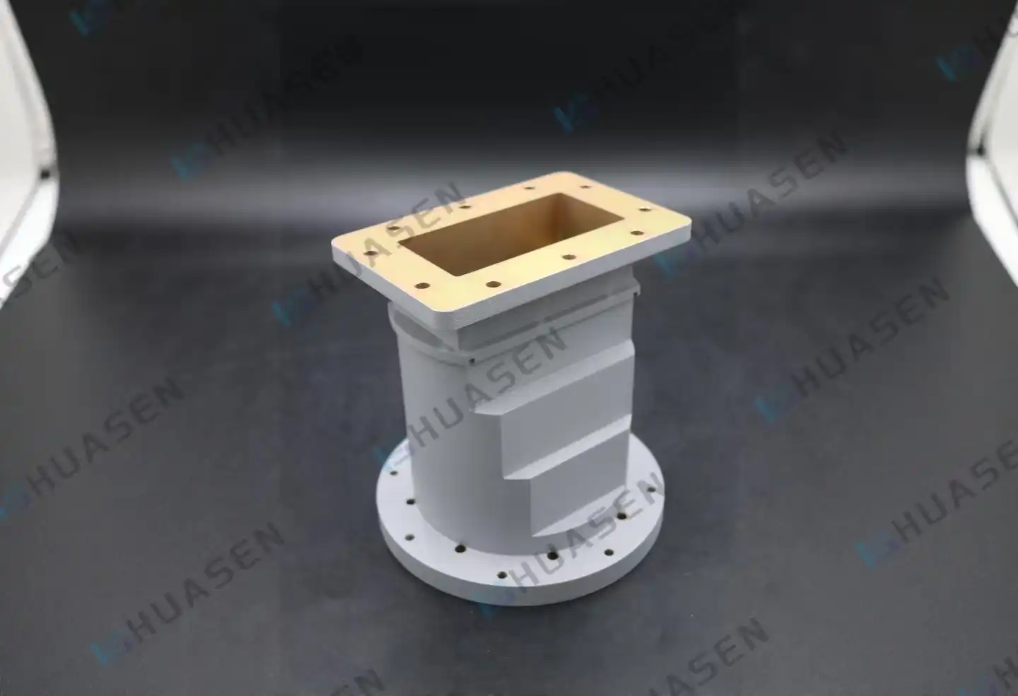
Comparing Waveguide Transition Options for Radar Front-End Applications
Waveguide-to-Waveguide Transitions
Either tapered or stepped impedance matching sections are needed to connect two rectangular waveguides that are of different sizes. Tapered waveguide transitions have a wider bandwidth and lower VSWR, often reaching 1.10:1 across the whole waveguide band. However, they are longer and may not be able to fit in tight areas like radomes or equipment racks. Using quarter-wave transformer sections for stepped changes gives you the same performance in a smaller package, but the bandwidth gets a little smaller as you add more steps.
When designers of radar systems look at space-limited integration situations, like putting multiple channels in a phased array transmit/receive module, small stepped transitions give them the performance-to-size ratio they need. In pulsed radar applications, these parts can usually handle peak powers of more than 10 kilowatts without dielectric breakdown because air is used as the insulation medium instead of the more fragile plastic or PTFE materials found in coaxial lines.
Coaxial-to-Waveguide Adapters
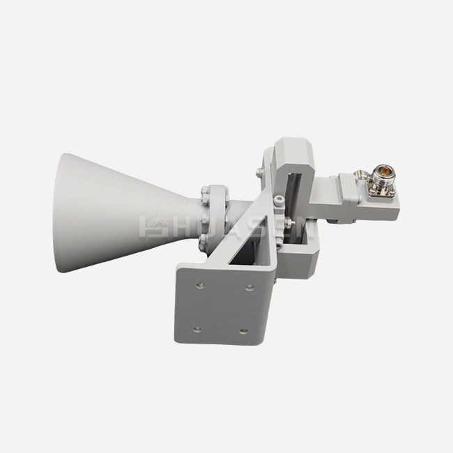
Vector network analysers and signal generators often have precision 2.92 mm, 3.5 mm, or Type-N connections, which means that test equipment integration often needs coaxial links. Coaxial-to-waveguide launchers use probe antennas to connect electromagnetic fields from the coaxial centre wire to the waveguide cavity. The depth and direction of the probes are carefully chosen to keep VSWR as low as possible.
The coaxial connection limits the amount of power that these adapters can handle. Depending on the frequency and duty cycle, this limit is usually between 100 and 500 watts. Metrology-grade rockets with VSWR below 1.15:1 are good for lab calibration sets because they make sure measurements are accurate enough to meet ISO 17025 standards. In the same way, production test stations that check the output power of radar modules depend on these connections to send data to spectrum analysers and power metres without changing the accuracy of the measurements.
Environmental Resilience and Integration Complexity
Outdoor radar systems on ships, coastal observation towers, or mobile military vehicles are subject to changes in humidity, shock loads, and temperature changes from -55°C to +85°C. Designers choose changes that are completely sealed and have environmental seals that meet IP67 ingress protection ratings. This keeps moisture out of the internal spaces, which could damage electrical performance or cause rust.
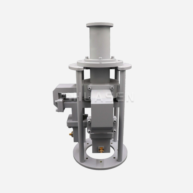
When changes have to account for twist angles or spatial offsets, they become more difficult to integrate. When radar antennas are placed on pedestals that can rotate, they often need transitions that change the waveguide size and make 90-degree bends so that signals can pass through mechanical bearings. To make sure that internal echoes stay below -25 dB across the working band, these compound transitions need to be carefully simulated using finite element analysis.
Procurement Guide: How to Buy Waveguide Transitions for Radar Systems?
Critical Purchasing Criteria
When buying parts for multi-year radar projects, procurement managers look at suppliers based on wait times, pricing structures, and the ability to make changes. Standard catalogue waveguide Transitions ship in two to four weeks. Custom-designed units with non-standard frequency coverage, specific flange pairs, or mounting brackets may take eight to twelve weeks for planning, prototyping, and production.
Prices change a lot depending on the size and complexity of the order. A simple WR-90 to WR-75 adapter could cost $200 to $400 per unit when bought in groups of ten. On the other hand, a custom Ka-band coaxial launcher with built-in bias tees and weather seals could cost more than $1,500 per unit. If you buy more than 50 units, you can usually get a discount. This makes starting to work with providers early helpful for projects that need dozens or even hundreds of channels.
Supplier Landscape and Selection
Companies that have been around for a while have built their names on certain technical skills, like circular waveguide transition. Some suppliers are very good at making ultra-broadband designs that work across multiple octave frequency ranges. This lets a single shift handle multiple radar modes. Others focus on handling high power for transmit chains in ground-based surveillance radar, while niche makers work on small transitions for phased-array uses that are limited by space.
When procurement teams look at possible partners, they should ask for S-parameter data files that can be put into system modelling tools and mechanical models in STEP or IGES forms so they can be used with CAD. For aerospace uses, suppliers with ISO 9001 approval and AS9100 compliance give more faith in quality management systems and the paperwork needed for defence contracts to track things.
Custom Versus Catalogue Components
Off-the-shelf transitions work well for many uses, especially when interface standards match up with popular waveguide bands and flange types. When radar systems need unusual frequency splits, need to integrate with special mechanical interfaces, or need performance optimisation beyond what is specified in a catalogue, custom designs are needed.
To quickly get unique quotes, you need to give specific information like frequency range with a margin, maximum VSWR tolerance, power handling needs, working conditions, flange types with dimensional models, and expected quantities. Suppliers can come up with the best solutions that balance performance, cost, and the ability to be manufactured when buyers and sellers are clear about supply dates and budget limits.
Performance Optimisation and Design Best Practices in Waveguide Transitions
Understanding Loss Mechanisms
There are three main things that can go wrong with signal transfer through waveguide transitions: reflection due to impedance mismatches, absorption in metal surfaces because of their limited conductivity, and mode conversion that wasn't meant to happen. When the shape of something suddenly changes, it creates breaks in the characteristic impedance. These breaks send power back to the source instead of to the load.
Electromagnetic fields can pass through conductor surfaces up to a certain depth, which is usually a few micrometres at microwave frequencies. This is called absorption loss. When the surface is rough, the effective path length that the current has to travel grows. This makes resistance go up and power escape as heat. This loss process is lessened by specifying internal surface finishes that are 32 microinches or better. This is especially important above 40 GHz, where skin depth drops below one micron.
Design Validation Through Simulation
Modern electromagnetic modelling software lets engineers simulate how a shift will work before they actually make it. Full-wave models figure out how the electric and magnetic fields are spread out in a part and predict S-parameters, mode content, and current densities on metal surfaces. Resonances, standing wave patterns, and accidental interactions that would only show up in lab tests can be found with these tools.
Most of the time, validation procedures match data from prototype units tried on calibrated VNA equipment with data from simulations of how well they work. There should be agreement within 0.1 dB for insertion loss and 1 dB for return loss across the whole frequency range. This means that the computer models are accurate and can be used to guide future design changes or scaling to nearby frequency ranges.
Material Selection for Durability
There are trade-offs between aluminium and copper buildings that go beyond how well they carry electricity. Copper is 40% more conductive than aluminium, which means it has a slightly lower insertion loss. This is an important benefit in long signal chains with many changes. Copper also has better dimensional stability when it comes to temperature cycling, keeping its precise internal shape that keeps impedance matched.
Because aluminium is lighter than other materials, it is used on platforms where carrying capacity is limited by mass budgets. Aluminium circular waveguide transition transitions that are finished with alodine chromate conversion coatings or anodising protect against rust and are useful for aircraft-mounted radar systems, satellite payloads, and small test equipment. For some uses, copper-plated aluminium is a good compromise because it keeps aluminium's low density while getting most of copper's conductivity.
Conclusion
Waveguide transitions are very important in current radar front-end designs because they connect different types of transmission lines and keep the signal's integrity even in harsh electrical and environmental conditions. As radar systems move towards higher frequencies, bigger bandwidths, and tighter integration limits, these parts change by using better materials, making them more precise, and improving how they conduct electromagnetic waves. By balancing performance, cost, and the abilities of the provider, strategic buying choices set radar projects up for success in both the defence and business markets, which are very competitive. Engineers and purchasing workers can find the best answers for their needs when they understand the technical roots and new trends.
FAQ
1. How do I determine the appropriate waveguide transition type for my radar system?
Which waveguide transition to use depends on the needs of your interface, the frequency band, the power levels, and the surroundings. Tapered transitions offer a wider bandwidth when joining two rectangular waveguides of different sizes, while stepped designs offer shorter physical lengths. It is possible to integrate test tools with coaxial-to-waveguide connections, but they have power limits. Check the VSWR specs against the budget for your system link and make sure that insertion loss doesn't lower the receiver's sensitivity or the transmitter's power. Think about technical limitations like mounting room, flange compatibility, and whether outdoor installations need to be sealed against the elements.
2. What quality assurance processes ensure reliable transition performance?
Reputable makers use more than one stage of proof. Testing with a vector network analyser checks the S-parameters over the whole frequency range and makes sure that the insertion loss and return loss meet the requirements without any resonance issues. Coordinate measuring tools check that the flange is flat and that the aperture measurements stay within 0.02 mm of the limits. This stops RF leaks. Thermal cycling from -55°C to +85°C and salt spray testing according to ASTM B117 are two types of environmental stress screens that check for rust resistance. Using X-ray fluorescence to check the thickness of the plating makes sure that the conductive coatings meet the skin depth standards for your working frequency.
3. Can custom transitions be developed for non-standard frequency ranges?
Of course. Custom engineering takes care of odd frequency splits, unique mechanical connections, or performance improvements that go beyond what is listed in a catalogue. The first step is to make precise requirements specs that include the frequency range, VSWR tolerance, power handling, environmental conditions, and sketches of the interfaces. Before making a prototype, electromagnetic modelling tools make models of suggested designs that show how well they will work. For special units, the lead time is usually eight to twelve weeks, which includes engineering analysis, making a sample, testing it to make sure it works, and making production tools. Getting suppliers involved early on helps make sure that unique designs are in line with project plans and budgets.
Partner With Huasen Microwave for Your Waveguide Transition Needs
Since 1993, Huasen Microwave Technology has provided high-quality RF and microwave parts to radar integrators, defense companies, and infrastructure makers for telecommunications around the world. Our engineering team specializes in designing unique Waveguide Transitions. We can help you with everything from simple rectangular adapters to complicated multi-mode converters that are best for your frequency bands and mechanical limitations. As a reliable Waveguide Transition manufacturer, we keep strict quality control systems that meet ISO 9001 standards. We also offer expert support throughout the whole procurement process, from helping you figure out your exact needs at the beginning to delivering your order and giving support in the field. Get in touch with our sales team at sales@huasenmicrowave.com to talk about your radar front-end integration needs and get specific quotes from a company with decades of experience making microwave components.
References
1. Balanis, Constantine A. "Advanced Engineering Electromagnetics, 2nd Edition." John Wiley & Sons, 2012.
2. Pozar, David M. "Microwave Engineering, 4th Edition." Wiley Global Education, 2011.
3. Collin, Robert E. "Foundations for Microwave Engineering, 2nd Edition." IEEE Press Series on Electromagnetic Wave Theory, 2001.
4. Marcuvitz, Nathan. "Waveguide Handbook." IET Electromagnetic Waves Series, Institution of Engineering and Technology, 1986.
5. Saad, Theodore S. "Microwave Engineers' Handbook, Volume 1." Artech House Publishers, 1971.
6. Rizzi, Peter A. "Microwave Engineering: Passive Circuits." Prentice Hall International Series in Electrical Engineering, 1988.
Send Inquiry