Improving Efficiency in Multi-Input Coaxial Power Combiner Systems






2026-07-08 22:23:45
To make multi-input coaxial power combiner systems more efficient, you need to pay close attention to design optimisation, material choice, and strict testing methods. A coaxial power combiner is a passive RF part that takes in multiple signals and combines them into a single high-power output. It does this while keeping the signal's impedance matching and consistency over certain frequency bands. More efficiency means less insertion loss, better isolation between input ports, and better thermal management. These are all important for 5G infrastructure, satellite communications, radar systems, and aerospace platforms, where mission success depends on power handling and reliability.
Assessing Current Performance Challenges in Multi-Input Coaxial Power Combiner Systems
Multi-input power combining designs have performance problems that don't go away. These problems have a direct effect on system reliability and running costs. When procurement workers look at suppliers and part specs, knowing these limits helps them make smart choices.
Signal Loss and Attenuation Issues
One of the biggest problems with RF power combining networks is still insertion loss. Every link point, transmission line section, and combiner junction adds resistive losses that lower the efficiency of the whole system. When there is more than one input, cumulative losses can lower the transferred power by 15 to 20% compared to the theoretical maximums. The coaxial layout is better than planar designs because it creates fully protected electromagnetic settings that reduce radiation loss and outside interference. Changes in temperature make attenuation problems worse because circuit resistance goes up with heat. This creates a feedback loop where higher power use causes thermal stress that hurts performance even more. If you don't use the right temperature management methods, systems that work outside or in harsh industrial settings break down faster.
Frequency Bandwidth Limitations
Another important bottleneck is limited operational speed. Many older power combining devices were made to work with small frequency ranges and only one application at a time. For modern communication systems to work with more protocols and frequency assignments at the same time, they need wider bandwidth coverage. When impedances don't match up at the edges of a band, standing waves form that make power flow less efficient and can damage amplifier steps further upstream. There is a clear link between the size and frequency performance of coaxial combiners. For example, for lower-frequency uses, longer quarter-wave sections are needed, which makes the device bigger and more complicated. Because of this connection, engineers have to choose between small form factors and high-speed performance.
Thermal Management Constraints
Power handling capacity in multi-input joining networks is limited by their ability to get rid of heat. To keep individual amplifier units safe from reflected energy, isolation resistors let uneven power escape as heat. When temperature loads are higher than what was planned, these resistors age faster, which makes them less effective at isolating over time. The coaxial structure has better thermal transfer paths than microstrip technologies, but it still needs good heat sinking to keep running at high power for a long time. For military and aircraft uses that work in temperatures ranging from -40°C to +85°C, special materials and building methods are needed to keep the electrical properties fixed during environmental cycling.
Identifying Key Bottlenecks Affecting Efficiency
Design, manufacturing, and operating factors that work together to limit system performance cause efficiency limits. By identifying specific bottlenecks, tailored optimisation techniques can be used.
Design and Material Limitations
How well RF energy moves through the joining network depends on how well the impedance matching works. Manufacturing flaws in the sizes of connectors, the characteristic impedance of transmission lines, and the shapes of junctions cause phase and amplitude mismatches that add up over time. If there are phase differences between input ports that are more than 10 degrees, vectorial power cancellation happens. This cancels out energy as heat instead of adding to the total output. These changes are kept to a minimum by high-quality materials that are good at conducting electricity and staying stable at high temperatures. Putting silver and gold on copper wires lowers skin effect losses at higher frequencies and protects against rust, which keeps performance stable over time. At millimetre-wave frequencies, where physical errors drop to micron levels, manufacturing accuracy becomes more and more important.
Environmental and Operational Stresses
RF parts such as coaxial power combiners are exposed to mechanical vibrations, changing temperatures, wetness, and toxic atmospheres in the real world. The salt spray in the air can damage metal surfaces and connector ports in maritime communications devices. Wind loading and temperature changes put stress on mechanical parts that are placed on poles for the front end of base stations. During takeoff, aerospace bases experience very high levels of vibration or turbulence, along with quick changes in pressure and temperature. These forces weaken mechanical links, cause tiny cracks to appear in solder joints, and speed up the wear and tear on materials. When choosing components, these operating facts must be taken into account. This can be done by using the right environmental tests and certification standards, such as MIL-STD-202 for shock and vibration protection.
Optimisation Principles for Enhancing System Efficiency
To get around the natural limits of efficiency, strategic optimisation methods use cutting-edge design methods and high-quality parts. Understanding the basic ideas helps with making specifications and judging suppliers.
Low-Loss Architecture Design
Choosing the right structure and designing the transmission lines are the first steps in minimising insertion loss. Radial combiner designs spread out input ports evenly around a central output junction. This makes all the electrical paths equal lengths, which automatically balances phase relationships. This shape works great for high-count merging tasks where binary tree structures would lose too much information due to multiple splitting steps. Careful choice of gearbox line resistance values improves power flow while keeping the ability to make the product. At changeover spots, quarter-wave impedance transformers make sure that impedance changes are smooth, which reduces reflections over a wide frequency range.
Advanced Material Selection
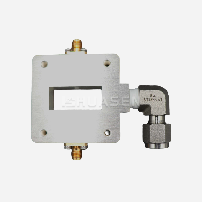
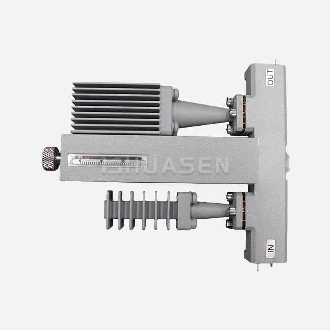
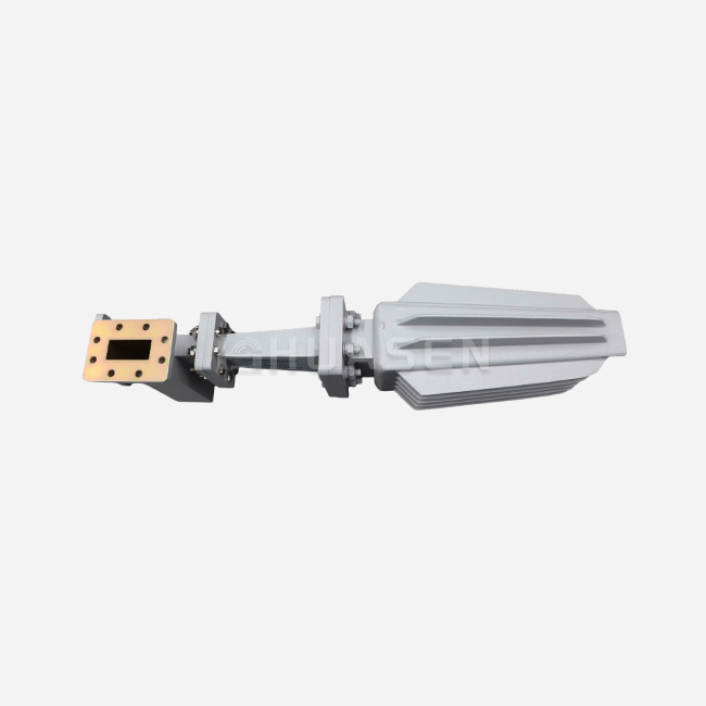
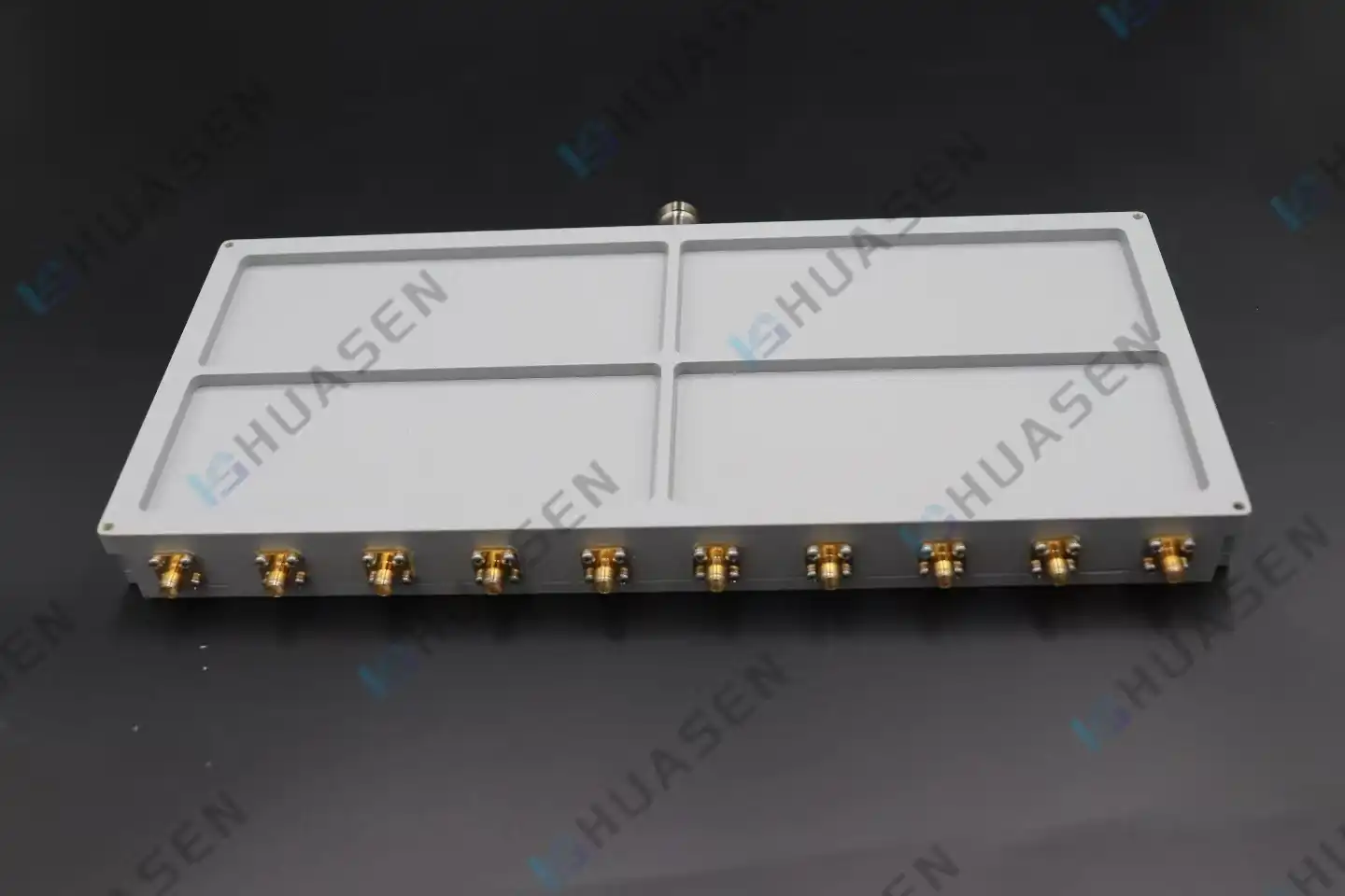
Huasen Microwave's coaxial power combiners use radial line combiner technology that is designed to provide great high-frequency stability across the DC to 40 GHz operating ranges. This way of thinking about design makes power distribution safe in radar and satellite communication systems that need to keep the integrity of the signals. By choosing the right combination ratios, such as 1:2, 1:3, 1:4, 1:8, and 1:10 setups, system designers can perfectly match device specs to amplifier designs without adding extra complexity or cost.
The quality of the components has a direct effect on how well the electricity system works and how long it lasts. Copper alloys with high conductivity allow for low signal loss while still keeping mechanical strength for strong connector contacts. When choosing a surface treatment, cost and efficiency need to be balanced. Silver coating has the lowest resistance losses, but it needs to be handled carefully so that it doesn't tarnish. Even though the loss tangent is slightly higher, gold plating has better corrosion protection and longer operating life in tough settings. Dielectric materials used in connector contacts and isolation structures need to have stable electrical qualities across a wide range of temperatures and absorb little water. PTFE-based dielectrics work very well at high frequencies and are stable at high temperatures, making them ideal for tough uses.
Comparative Technology Analysis
When you know about other ways to combine signals, you can see where coaxial systems have clear benefits. Wilkinson combiners with a microstrip design have small sizes that make them good for integrating circuits, but they can't handle a lot of power because the base gets too hot. Waveguide-based combiners work best at millimetre-wave frequencies and have very low insertion loss. However, they need to be precisely aligned mechanically and take up a lot more space. The coaxial method strikes a good mix between the ability to handle a lot of power, good broadband performance, and strong mechanical properties for the largest number of uses. Flexible deployment includes everything from lab test tools to ruggedised field equipment that doesn't need major design changes.
Implementation Strategies and Techniques for Efficiency Improvement
Theoretical speed benefits can only be seen when the system is installed correctly and managed on a regular basis. Implementing the design in real life is what shows if the design's skills are useful.
Assembly and Installation Best Practices
How you handle connectors has a big effect on how well and reliably your system works. When connecting two connectors, using the right amount of force makes sure that the electrical contact is perfect without overstressing the mechanical threads, which could cause them to break early. Particles can damage mating surfaces, and contamination control keeps them from doing so. For example, a single dust particle in a millimetre-wave connection can cause a lot of return loss decline. Cable routing keeps bend radii from being too small, which changes the way the transmission line works, and minimises the mechanical stress on connection contacts. Support braces spread out the weight and sound loads that would normally put a lot of stress on the connection points.
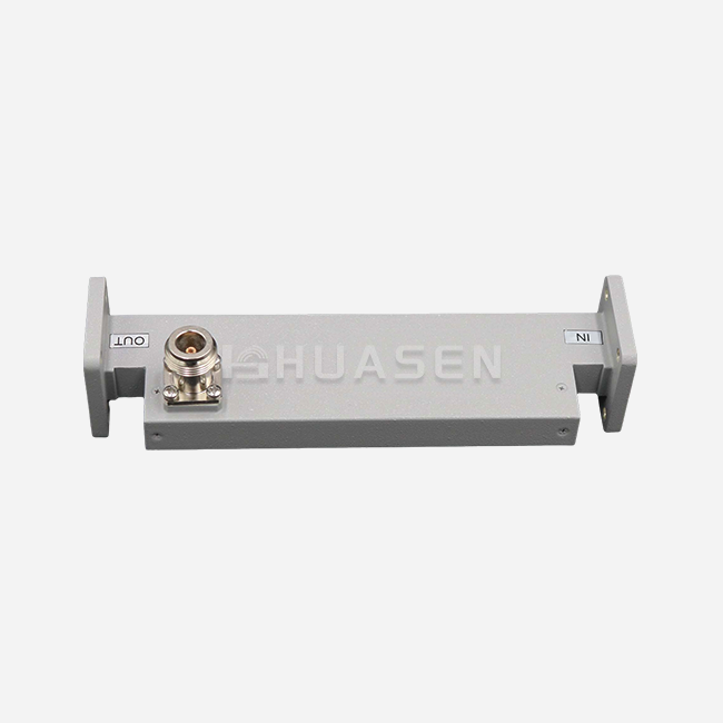
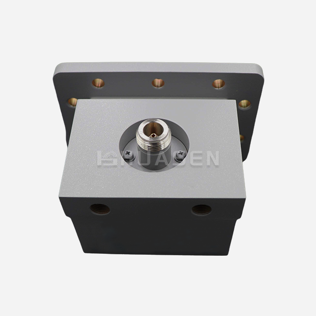
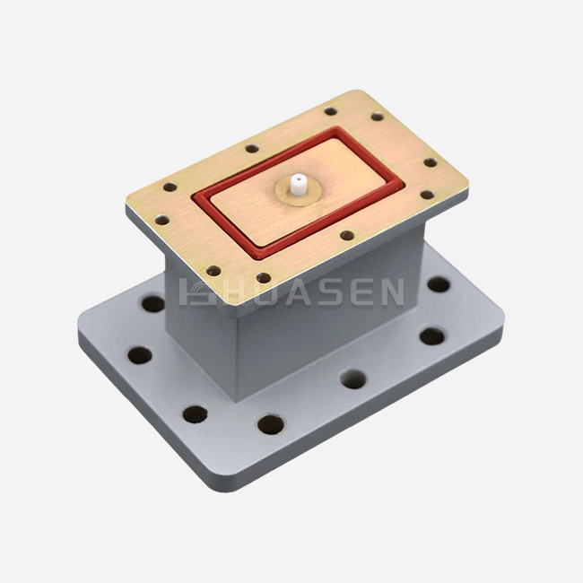
Huasen Microwave creates combiners; they make sure that they work with a wide range of current infrastructure by using industry-standard connector interfaces like N-type, SMA, 2.92 mm, and 5339K. This standardisation makes merging easier while using interface designs that have been used before and have a lot of field reliability data. The ability to handle a lot of power lets demanding apps work without having to build a custom interface, which could bring failure modes that haven't been tried yet.
Quality Assurance and Testing Protocols
A lot of testing before release makes sure that systems (coaxial power combiners) that have been put together work as expected in real-world situations. The Vector Network Analyser takes measures of S-parameters over the whole operating bandwidth to make sure that design goals for insertion loss, return loss, and port-to-port isolation are met. High-power burn-in testing at rated continuous wave power levels for long periods of time shows that thermal management is adequate and finds breakdowns that cause infant mortality before the system is put into use in the field. When it comes to telecommunications, passive intermodulation testing is very important because third-order goods can mess up the operation of the receive band. Mechanical inspection checks the stability of the connection contact, the quality of the plating, and the right way to apply torque, which guarantees long-term dependability.
Continuous Monitoring and Maintenance
By finding signs of wear and tear early on, proactive repair programmes increase the life of equipment and make it available for as long as possible. Taking regular readings of the S-parameters shows when insertion loss rises, which can mean that problems are starting to show up, like connection corrosion or isolation resistor ageing. Using thermal imaging during operation can find hot spots that mean there isn't enough heat sinking, or power distribution isn't even. Checking the connector link during regular repair times finds wear patterns before they make the system work less well. These tracking methods allow for planned actions that cut down on unplanned downtime and stop catastrophic failures that could damage pricey amplifier stages upstream.
Verification of Optimisation Results and Business Implications
Quantifying improvements in performance gives buying choices the proof they need and backs up engineering investments in system optimisation.
Performance Metrics and ROI Analysis
A lot of data collected before and after system improvements shows that the changes had real effects. Even a 0.5 dB drop in insertion loss can save a lot of power or make a communications system's service area bigger. Better separation between input ports lowers stress on the amplifier and increases the useful life of parts, which lowers the total cost of ownership by lowering the number of times they need to be replaced. Better temperature performance lets higher power operation happen in current form factors, which raises the system's capabilities without changing the infrastructure. These measurable gains back up estimates of return on investment that show why high-quality parts should be used, and strict implementation processes should be followed.
Strategic Supplier Partnerships
Long-term procurement success depends on choosing manufacturing partners that can provide stable quality and quick technical help. When evaluating a supplier, you should look at their manufacturing skills, quality control systems, and the design engineering tools they have to help with custom changes. Certification to important industry standards, such as ISO 9001 quality management and RoHS product compliance, shows that a company is dedicated to doing its best. Stability in the supply chain and the ability to make a lot of things at once make sure that project plans are met by the availability of parts. Rapid development and sample evaluation speed up the process of validating designs and lower the time it takes to get new systems up and running.
Well-known companies that have been making RF components, such as coaxial power combiners, for decades, bring a lot of useful information about how they are used to the process of developing specifications. This knowledge helps people figure out how to balance different success criteria and cost concerns. Having access to all test data and application notes lowers the risk of design mistakes and speeds up merging. Long-term component reliability can be assured by responsive after-sales support that includes testing data, repair help, and the ability to analyse failures.
Conclusion
To make multi-input coaxial power combiner systems more efficient, you need to pay attention to all of their parts: the design, the materials you choose, the quality of the manufacturing, and the operations you run. Advanced radial combiner designs keep port-to-port separation high across a wide frequency range while minimising insertion loss. High-quality materials and precise manufacturing give mission-critical uses the electrical performance and weather toughness they need. Strategically choosing suppliers makes sure that you can get technical help and reliable supply lines that can meet the needs of even the most difficult projects. These combined methods turn theoretical performance capabilities into real-world operating capabilities. This makes systems more reliable, extends their useful life, and gets the most out of investments in infrastructure.
FAQ
1. What causes insertion loss in multi-input power combiners?
Several things can cause insertion loss, such as resistive losses in wires and connectors, dielectric losses in insulating materials, and mismatch losses at impedance changes. Complete electromagnetic protection in the coaxial structure keeps radiation losses to a minimum. At each junction and joining point, there is an extra loss that builds up through the combined network. How big these losses are depends on how conductive the material is, how well the surface is finished, and how precisely it was made.
2. How does environmental stress affect combiner performance?
Changes in temperature can change the dielectric and conductor qualities, which can cause electrical performance to go beyond what was planned. Mechanical vibrations can make connection surfaces loose and cause contact problems that come and go. Ingress of moisture ruins metal surfaces and makes it harder for conductors to stay separate. Sealing off the surroundings correctly and choosing the right materials can lessen these effects.
3. Can a single combiner cover multiple frequency bands?
Broadband combiners with well-thought-out impedance transformers and transmission line sections can cover an octave or more of frequency. Because component measurements depend on wavelength, the physical size gets bigger at lower frequencies. When it comes to performance, the trade-offs between bandwidth, insertion loss, and power handling ability need to be optimised for each application.
Partner with a Trusted Coaxial Power Combiner Manufacturer for Your RF Solutions
Every project that Huasen Microwave works on is backed by more than 30 years of specialised experience making high-frequency microwave and millimeter-wave parts. Our Coaxial Power Combiners work with frequencies from DC to 40GHz and have adjustable splitting ratios and strong power handling for use in radar, aircraft, defence, and telecoms. Standard setups for connectors make merging easy, and our engineering team offers full design help and customisation services. We have strict quality standards and testing procedures that make sure our products work reliably even in the toughest conditions. Email our team at sales@huasenmicrowave.com to talk about your unique needs and find out how our technical know-how can help your RF system work better.
References
1. Pozar, David M. "Microwave Engineering, 4th Edition." John Wiley & Sons, 2012.
2. Wilkinson, Ernest J. "An N-Way Hybrid Power Divider." IRE Transactions on Microwave Theory and Techniques, vol. 8, no. 1, 1960, pp. 116-118.
3. Cripps, Steve C. "RF Power Amplifiers for Wireless Communications, 2nd Edition." Artech House, 2006.
4. Kumar, Anil, and Shiban K. Koul. "Microwave and Millimeter Wave Power Amplifiers: Analysis, Design and Performance." Springer, 2016.
5. Fusco, Vincent F. "Microwave Circuits: Analysis and Computer-Aided Design." Prentice Hall, 1987.
6. Collin, Robert E. "Foundations for Microwave Engineering, 2nd Edition." IEEE Press, 2001.
Send Inquiry