Beam Steering Accuracy in Microstrip Conformal Array Antenna Systems






2026-07-08 09:14:33
In microstrip conformal array antenna devices, beam steering accuracy tells us how exactly the energy can be sent to a target. This accuracy has a direct effect on signal quality, interference suppression, and link stability in a wide range of settings, from 5G base stations to interactions in space. When conformal arrays are placed on curved surfaces, phase deviation problems arise that need to be carefully managed through compensation methods, precise manufacturing, and substrate selection in order to keep beam control tight and performance consistent across all working frequencies.
Understanding Beam Steering Accuracy in Microstrip Conformal Array Antennas
Beam steering is the mechanical rerouting of radiated energy without moving the antenna itself. This is an important skill for communication settings that change quickly. In contrast to traditional mechanically guided systems, conformal arrays achieve this by finely adjusting the phase of each radiating element. This allows for quick reaction times and multiple beams to be sent at the same time.
The Fundamentals of Electronic Beam Steering
Electronic beam direction depends on both good and bad wave disturbances. When signals from several antenna parts arrive at a faraway location at the same time, they join in a way that makes a strong beam. We change the direction of maximum radiation by adding estimated phase delays at each element. Because of this idea, our phased array systems can switch beams 100μs quickly and scan up to ±60°, which gives them the flexibility to follow moving objects or help multiple people at the same time.
Conformal Geometry and Its Impact on Phase Control
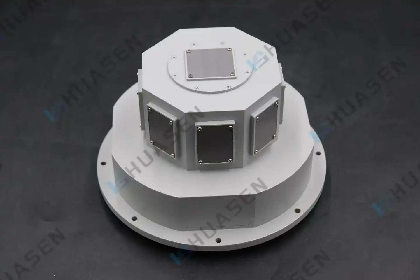
When you mount antenna elements on objects that aren't flat, you get geometric phase mistakes that you never see with flat arrays. Because of the curvature, parts face slightly different directions, which changes the path length and throws off the phase consistency. To keep the beam-pointing error below 0.5° in a cylindrical fuselage installation, which is widespread in aircraft uses, you need to use complex correction methods. Our Microstrip Conformal Array Antenna solutions have geometric adjustment methods that map the physical curvature and apply compensating phase shifts. This keeps the 18°×18° beamwidth fixed no matter the shape of the mounting surface.
Critical Factors Affecting Steering Precision
Overall direction precision is based on a number of technical factors. Mutual coupling between elements that are close to each other causes unexpected electromagnetic interactions that change the way the phases should be related. The qualities of the substrate material, especially how stable the dielectric constant is across temperature ranges, have a direct effect on phase velocity and, by extension, beam direction. Tolerances in the spacing between elements during production, even ones as small as 0.1 mm, can cause phase mistakes that add up over a big array. We deal with these problems by using coordinate measuring machines and vector network analyser testing to make sure that S-parameters are correct before they are put into use.
Challenges and Performance Bottlenecks in Beam Steering
In the real world, conformal array applications run into a number of technical problems that make steering precision difficult. Knowing these limits helps buying teams set reasonable goals for performance and choose solutions that work well for their needs.
Beam Squint and Phase Error Mechanisms
Beam squint happens when the direction of the beam changes with frequency. This problem is made worse in conformal arrays by the different phase delays caused by curves. As the frequency goes up, the lengths of the electrical paths between the elements change in a way that isn't proportional to the frequency. This makes the beam "squint" away from where it's supposed to go. This effect is especially annoying in wideband applications, where keeping the beam direction the same across a 10% bandwidth—which is normal for our circularly polarised directed arrays with a 3–12 dB gain range—needs careful feed network design and element spacing optimisation.
Radiation Pattern Distortion on Curved Surfaces
When antenna elements of a microstrip conformal array antenna are shaped like cylinders or spheres, the transmission patterns of each element no longer point in the same direction. This geometry error makes the main beams not even and the sidelobe levels high, which lowers the signal-to-interference ratios. These errors are shown by far-field radiation pattern testing in anechoic chambers, which helps engineers find blind spots or nulls that they didn't expect. Our design method includes correcting element patterns by strategically forming sub-arrays and lowering amplitudes. This restores pattern symmetry and cuts sidelobes by 8–12dB compared to designs that haven't been fixed.
Mutual Coupling Effects and Beamforming Degradation
One of the main things that limits accuracy is electromagnetic coupling between elements that are close to each other. When one element broadcasts, close elements act as parasitic receivers and send out new waves with different phases that mess up the beam pattern that was meant to be sent out. This connection gets stronger when the distance between elements drops below 0.5 wavelengths and gets stronger as the element number rises. This happens when there is more variation in the return loss and less accuracy in the direction, especially at wide scan angles. As part of our manufacturing process, we test the adhesive strength and check the Intermodulation Distortion (PIM) to make sure that the coupling effects stay within acceptable limits for high-power radar and telecommunications uses.
Advanced Techniques to Optimise Beam Steering Accuracy
To get around the problems that come with curved arrays, modern antenna design uses complex modelling tools and new ways of making things. With these methods, military-grade pointing accuracy can be reached while still allowing production to be scaled up.
Electromagnetic Simulation and Predictive Modelling
Full-wave electromagnetic models that use the Method of Moments (MoM) and Finite-Difference Time-Domain (FDTD) methods make it possible to optimise all aspects of pre-fabrication. These tools simulate mutual coupling, surface wave propagation, and conformal geometry effects all at the same time. They can accurately predict real beam patterns more than 95% of the time. Our engineering teams use these models to try out different plans for elements, changing their positions and the locations of feed points to reduce phase errors. Being able to test thousands of different design changes cuts development times by almost 40% and guarantees success on the first try for custom applications that need specific beam patterns or shapes.
Strategic Substrate Selection and Material Engineering
The material of the substrate has a direct effect on phase velocity stability, which is a key factor for keeping guiding accuracy even when temperatures change. PTFE composites with dielectric constants between 2.2 and 3.5 are very stable at high temperatures, staying the same phase from -55°C to +125°C according to standards for external stress testing. New liquid crystal polymer substrates have even smaller loss tangents, which makes millimetre-wave uses more efficient. When we choose materials, we make sure that the electrical performance is balanced against the mechanical conformability. This way, we make sure that the substrate's flexibility lets it conform to curves without causing delamination stress that could weaken its long-term reliability under vibration and thermal cycling, which is what MIL-STD-810 requires.
Precision Fabrication and Quality Assurance Protocols
The limits of how accurately handling can be are set by manufacturing margins. When we place elements, we use laser-assisted placement to get placement accuracy of ±0.05 mm, which is much better than normal photolithographic methods. Each output array goes through a lot of tests, such as checking the dimensions, making sure the VSWR stays below 2:1 using S-parameter validation, and measuring the radiation pattern to make sure the beam direction error stays within the limits. This strict quality control makes sure that customisation options, such as dual polarisation configurations and monopulse feed networks, keep working the same way across all production levels. This is very important for system designers who need to source parts reliably.
Comparative Analysis of Microstrip Conformal Array Antennas in Beam Steering
To choose the best antenna technology, you need to know how the different versions compare in terms of performance. The next study shows the choice factors that are important for procurement specifications.
Microstrip conformal array antenna grids (microstrip array antennas) are clearly better than fixed ones in many ways. Microstrip implementations are 60% lighter and 75% shorter than waveguide slot arrays. This is very important for aircraft platforms where every gramme counts when it comes to fuel economy. The technology lets electronic scanning happen without mechanical motion systems. This means that there are no moving parts that need to be maintained, and beam-setting speeds are five times faster than with motor-driven dishes.
There are, however, trade-offs. Parabolic reflectors with motorised steering can handle more power, which makes them better for ground-based radar systems that don't have to worry about weight or profile. Because they don't need to be geometrically corrected, phased arrays with standard patch elements on flat surfaces have slightly better steering accuracy—about 0.3° vs. 0.5° for conformal versions. But conformal designs make it possible to integrate platforms in a way that isn't possible with flat designs. For example, in UAV communication systems, grids wrap around the leading edges of the wings without affecting the aerodynamics.
These trade-offs are shown by real-life application situations. For 5G base station backhaul links that need to cover areas of about 60°, our phased array systems with 100μs switching speeds support dynamic beamforming that keeps track of mobile users while blocking interference from cells next to them. Maritime satellite communications are helped by conformal cylinder-mounted arrays that keep the link stable even when the ship rolls and pitches. Electronic compensation keeps the beam locked on geostationary satellites. For defence purposes, the stealth benefits of flush-mounted conformal arrays that get rid of radar cross-section contributions from exposed antennas are more important than the extra signal processing complexity needed for geometric phase correction.
Procurement Considerations and Trusted Suppliers
To find high-performance microstrip conformal array antenna arrangements, you have to look at more than just the basic requirements. For buying agreements to work, suppliers must be able to provide services throughout the whole lifecycle of a product.
Evaluation Criteria for Technical Skills
Custom microstrip conformal array antennas usually have lead times of 8 to 12 weeks because they need to be made with great care and tested individually. Suppliers that can do rapid prototyping and send the first samples within 3–4 weeks speed up development processes, which is very important for projects that need to be finished quickly. Cost-effectiveness for large orders depends on how well the production can be scaled up or down. Companies that have automated assembly lines for standard configurations (such as end-fire, dipole array, microstrip conformal array antenna, and slot array variations) offer better unit economics for quantities above 100 while still allowing for customisation for unique uses.
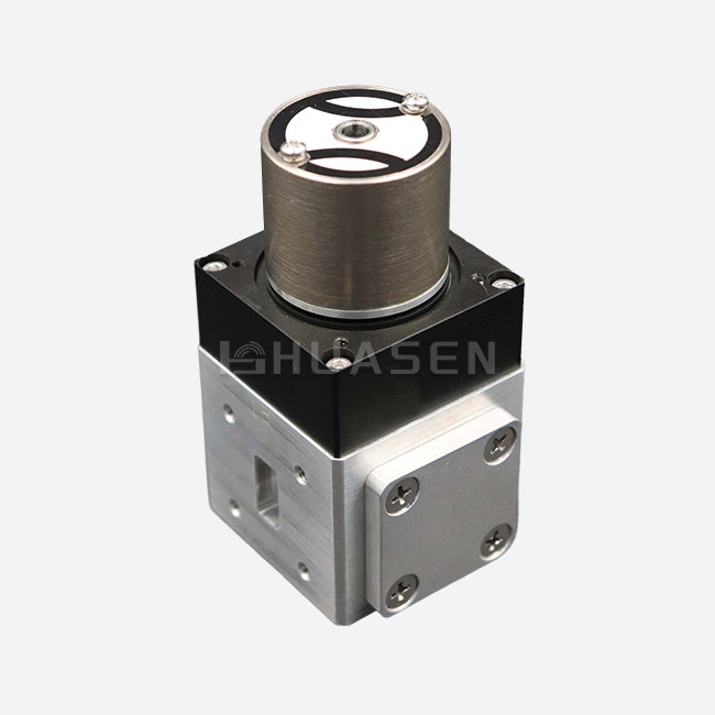
One big difference is that OEMs can customise their products. True design partners can change things like frequency, polarisation setup (including circularly polarised choices with stable axial ratio), and the mechanical interface to fit certain connection standards like SMA, K-type, or WR-series waveguide flanges. This adaptability is very important for putting antennas in tight areas like on drones, spaceships, or next-generation base station enclosures, where regular products won't work.
Quality Validation and Certification Standards
Following established standards is directly linked to supplier reliability. Compliance with IPC-6012 for rigid-flex printing boards protects the metal layer even when the structure is under stress. MIL-STD-810 approval verifies natural resilience, such as the ability to withstand vibrations, temperature shocks, and high altitudes. RoHS compliance takes into account the rules for markets in Europe and North America. Instead of depending only on self-declarations, procurement teams should ask for third-party test results that prove these certifications. This lowers the risk of failure in the field by a large amount.
Client examples from similar apps, like Microstrip Array Antenna, can give you useful information about how well something works. A supplier's history of providing similar arrangements for radar systems, satellite ground stations, or telecommunications infrastructure shows that they know what they're doing. Participation in industry benchmarks, like serving on IEEE antenna standards groups, shows professional leadership and a dedication to moving the field forward.
Conclusion
To get accurate beam direction in conformal array systems, you need to use advanced compensation methods to balance geometric problems. Curvature can cause phase mistakes and complicated coupling, but modern modelling tools and precise manufacturing make it possible for demanding applications to work reliably. The success of procurement relies on choosing providers with a track record of being able to customise products, strict quality standards, and quick technical support that goes from the initial design meeting to optimising products after deployment.
FAQ
1. How Does Surface Curvature Limit Steering Range?
A sharp curve makes phase errors build up across the array opening, which lowers beam quality as the scan angle gets bigger. For arrays on cylinders with sizes less than 10 wavelengths, scanning is usually limited to ±45° before the number of sidelobes becomes too high to be acceptable.
2. Can Conformal Arrays Support Multiple Simultaneous Beams?
Yes, with the help of computer beamforming systems. Our designs are scalable and can support either 1D or 2D element arrangements with individual phase and amplitude control. This lets multiple separate beams form, which is useful for base stations that serve many people or radar systems that are tracking multiple targets at the same time.
3. What Power Levels Can Microstrip Implementations Handle?
Most flexible microstrip conformal array antennas can handle up to 100W of power per piece. This can go up to 250W for certain radar uses with high-thermal-conductivity substrates and built-in heat sinking, but waveguide options are still better above these limits.
4. How Do You Maintain Performance Across Wide Bandwidths?
Stacking patch configurations and aperture coupling methods are used to improve bandwidth. These methods raise the effective bandwidth from 2% to 10% for basic patches, which is the same as the 10% bandwidth requirement for our circularly polarised directed arrays. They also keep the gain stable within the 3-12dB range.
Partner with Huasen Microwave for Precision Array Solutions
Huasen Microwave Technology has been a specialist in high-frequency radio systems for 30 years. As a well-known microstrip conformal array antenna manufacturer, we offer full solutions that include design optimisation, custom manufacturing, and thorough testing to make sure your arrays meet the highest standards for steering accuracy. Our engineering teams work directly with system developers to solve difficult problems, such as choosing the right substrate for harsh environments or improving the feed network for shaped beam uses.
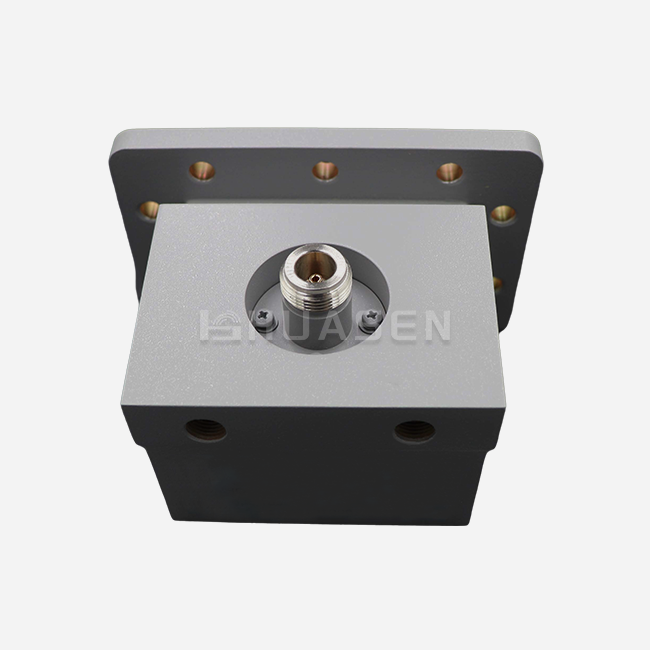
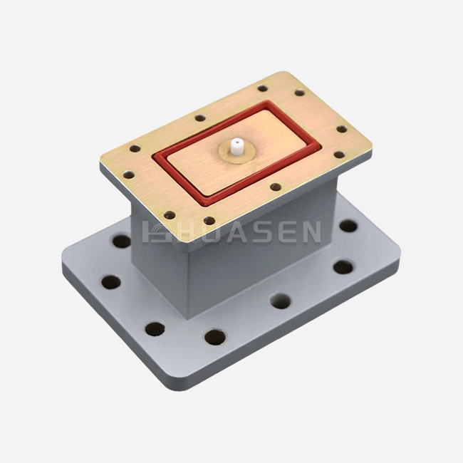
We can make standard Microstrip Conformal Array Antenna with 18dB gain and narrow 18°×18° beamwidths or fully custom phased arrays for aerospace systems. Our production skills range from making prototypes to mass production while still meeting MIL-STD requirements. Email our technology experts at sales@huasenmicrowave.com to talk about the details of your project. We'll give you accurate predictions of how well the product will work, prices that are cheap for the amount you need, and delivery dates for samples that will help you stay on schedule with your development.
References
1. Mailloux, R. J. (2017). Phased Array Antenna Handbook, 3rd Edition. Artech House.
2. Josefsson, L., & Persson, P. (2006). Conformal Array Antenna Theory and Design. Wiley-IEEE Press.
3. Kumar, G., & Ray, K. P. (2003). Broadband Microstrip Antennas. Artech House Antennas and Propagation Library.
4. Skolnik, M. I. (2008). Radar Handbook, 3rd Edition. McGraw-Hill Education.
5. Milligan, T. A. (2005). Modern Antenna Design, 2nd Edition. Wiley-Interscience.
6. IEEE Transactions on Antennas and Propagation. (2019-2024). Various articles on conformal array beam steering and phase compensation techniques. IEEE Antennas and Propagation Society.
Send Inquiry