Engineering Structure Behind Quadridged Horn Antenna Bandwidth Gain






2026-07-08 09:14:27
The Quad-ridged Horn Antenna's bandwidth gain comes from its four equally placed metallic ridges inside a curved waveguide. These ridges change the way impedance matching works across very wide frequency ranges. This ridge design lets it work continuously from 0.1 GHz to 40 GHz, with a stable gain range of 5 to 19 dB and excellent dual-polarization separation of more than 20 dB. The quadridged geometry solves important problems in EMC testing, radar calibration, and 5G system evaluation, where single-device multi-band coverage directly reduces capital spending and test cycle length. This is in contrast to traditional horn designs that are limited by narrow bandwidth.
Fundamentals of Quadridged Horn Antenna Design and Operation
Core Structural Components Driving Performance
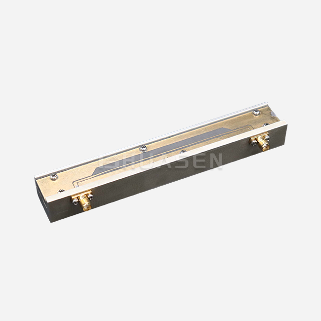
The quad-ridged horn antenna stands out because its parts are carefully designed to work together. At its base, four tapered metallic ridges run lengthwise from the throat to the opening. These are placed around the inside circumference of the waveguide at 90-degree angles. This ridge arrangement makes controlled capacitive loading that cancels out the inductive reactance that comes with wideband propagation. This makes it possible to achieve impedance transformation ratios that regular horns with smooth walls can't match.
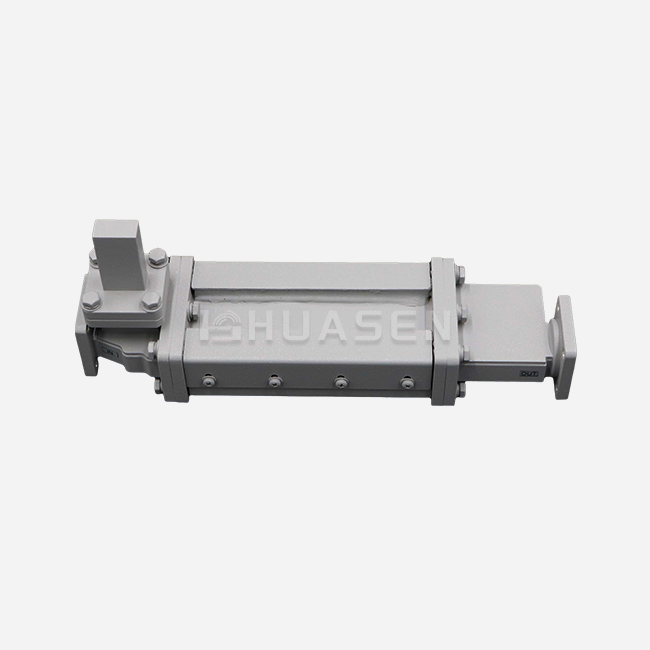
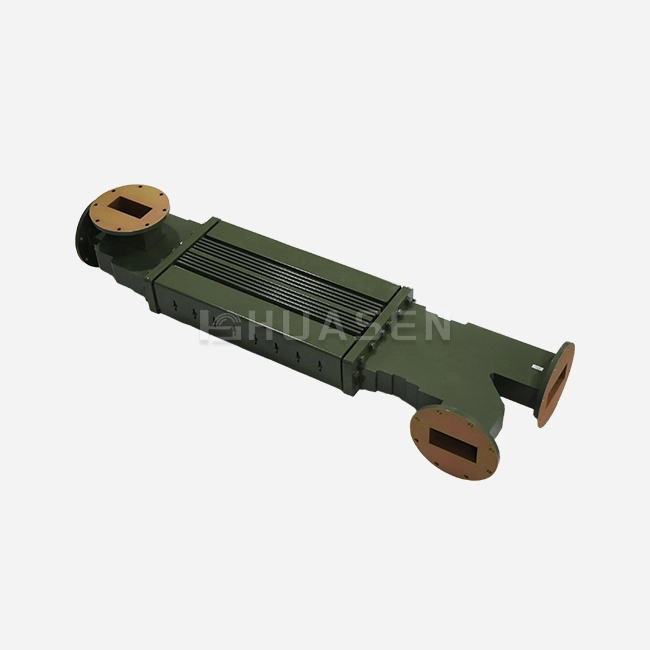
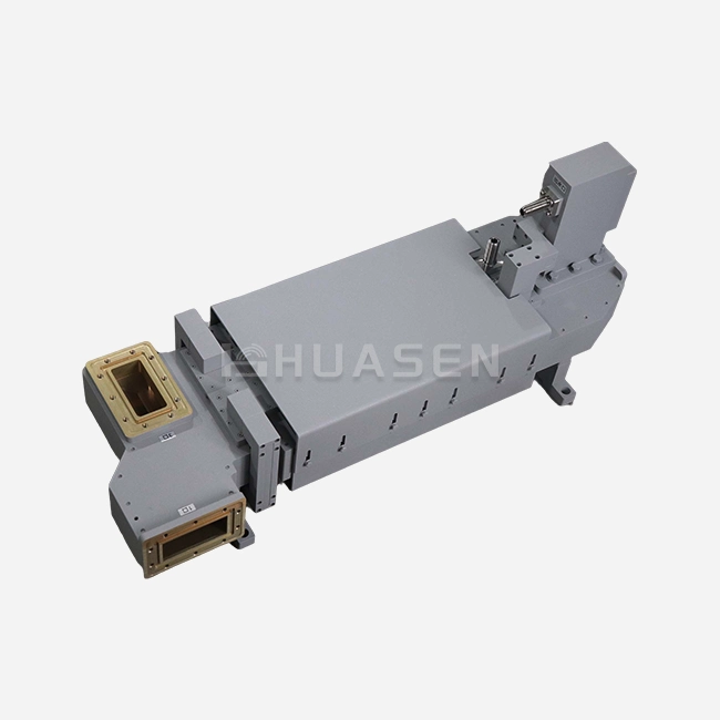
The flared opening shape is based on exponential or linear taper patterns that were carefully calculated to reduce reflections over bandwidths that span a decade. This way of engineering is shown by our Ultra-Wideband Dual-Polarized Quadridged Horn Antenna Series (DPHA), which has VSWR performance below 2.0:1 across operating ranges, while other designs need to switch antennas in the middle of a test. During manufacturing, the throat width and ridge gap sizes are controlled to the micrometer level, because differences bigger than 0.05 mm at millimeter-wave frequencies make cross-polarization discrimination worse.
Electromagnetic Field Distribution Principles
Field transmission in quadridged structures works in a very different way than in normal horn antennas. Because the ridge surfaces focus electromagnetic energy, they make mixed modes that mix TE and TM field components. This hybrid-mode propagation has two very important benefits: a lower cutoff frequency that lets it work in a lower frequency range without affecting its physical size, and better phase velocity control that keeps the radiation patterns stable as the frequency range changes.
When excited through two different ports, the antenna can handle both horizontal and vertical polarizations at the same time, and in laboratory-grade units, the separation usually goes above 25 dB. This feature is very useful for testing labs because it gets rid of the need for mechanical rotation devices during CISPR 25 car EMC tests. This lowers the measurement uncertainty caused by changes in position. The Boundary Open Dual-Polarized Quadridged Horn Antenna (DPOBHA) version makes this possible outside, where covering for the climate would normally hurt electrical performance.
Impedance Matching Mechanisms Across Multi-Octave Bandwidths
Getting a 50-ohm impedance display that stays the same from 0.1 GHz to 40 GHz is a big engineering problem that progressive impedance transformation helps quadridged designs solve. The ridge taper profile works like a spread matching network, with the characteristic impedance changing slowly in each lengthwise section. In stepped transformers, reflection coefficients are caused by sudden breaks, but this gradual shift stops them.
Modern ridge profile optimization of a quad-ridged horn antenna is based on advanced computer electromagnetics. It tries to balance the needs for low-frequency matching and high-frequency dispersion control, which can be at odds with each other. High-precision CNC cutting lets manufacturers keep ridge surface specs within ±0.02mm, which is important for making sure that performance stays the same from one production batch to the next. When buying, teams look at what suppliers can do; manufacturing precision paperwork is just as important as datasheet specs. This has a direct effect on how stable the calibration is over time in metrology applications.
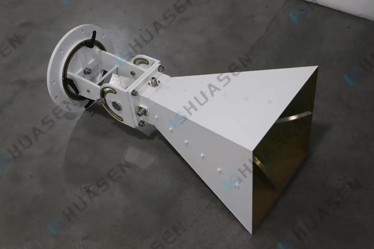
Comparative Analysis: Quadridged Horn Antenna vs. Alternative Horn Antennas
Performance Benchmarking Against Standard Gain Horns
Standard pyramidal gain horns are the most common type of horn used in narrow-band high-gain situations. They can usually work across 10–30% fractional bandwidths and have gains of 20–25 dB. However, they are not very useful in current wideband testing settings. A normal EMC test room that works with frequencies between 1 and 18 GHz needs six separate standard horns. Each one needs its own calibration, storage area, and handling routines, which slow down operations.
Quad-ridged horn antennas combine the need for six units into a single device that covers the whole band with a gain range of 5 to 15 dB. It means giving up a little more peak gain than optimized narrow-band horns, but this is fine for most measurement tasks where field uniformity and polarization purity are more important than exact gain numbers. For system designers who are making small test chambers, the extra space means bigger quiet areas within the same building size.
Double-Ridged Versus Quadridged Architecture Trade-offs
In the middle are double-ridged horn antennas, which can work across a wide frequency range with a single linear polarization. When polarization diversity is not needed, these devices work well in places like spectrum tracking or radar test areas. The easier two-ridge design usually costs 30–40% less than quadridged versions and can handle a little more power because the ridges are farther apart.
When testing needs to do fast polarization switching or dual-polarization detection at the same time, quadridged setups become necessary. This is shown by the fact that danger simulation systems used for defense electronic warfare tests have to copy real-world signals with any polarization state. Our DPHA series has six degrees of freedom adjustment mechanisms that allow for exact antenna positioning within ±0.1 mm of displacement accuracy. This is important for phase center alignment in small antenna test range setups.
Biconical and Log-Periodic Alternative Considerations
Because they can cover all directions and a wide range of frequencies, biconical antennas are often used for testing emitted signals below 1 GHz. Their lack of directionality, on the other hand, makes them less useful in controlled testing settings where blocking background noise is important. Log-periodic designs provide wider horizontal coverage, but the phase center moves around depending on the frequency, which makes it harder to change from near-field to far-field in antenna characterization jobs.
Quadridged horn antennas have phase centers that don't change much over their working bandwidth—usually less than λ/8 even across decade bandwidths. This steadiness is especially helpful when measuring radar cross-sections, since the accuracy of the target's position directly affects the truth of the measurement. When comparing different antenna technologies, procurement professionals who work with aerospace and defense contractors should focus on phase center stability specifications. This parameter doesn't get enough attention in standard datasheets, but it has a big effect on how accurately measurements can be repeated.
Engineering Challenges and Solutions in Maximizing Bandwidth and Gain
Overcoming Traditional Bandwidth Limitation Mechanisms
The bandwidth limits of conventional horn antennas come from the basic science of waveguides. As the frequency goes down, the waveguide dimensions needed to support propagation go up by the same amount. This makes it impossible to put useful systems in because of the physical size limitations. Higher-order mode activation changes radiation patterns and lowers polarization purity at the same time as frequency rises. In the past, these different limitations kept smooth-walled horns to small working ranges.
By fundamentally changing the waveguide's acoustic features, ridge loading breaks these usual rules. Because ridge surfaces add capacitance loads, the cutoff frequency is lowered without making the device bigger. The engineering teams at Huasen Microwave have improved ridge profile geometries by using electromagnetic simulations and real-world testing over and over again. They have now reached working lower bounds at 0.1 GHz in devices with aperture measurements that are useful in lab settings. With this new discovery, communications testing labs can combine their equipment stockpiles, which lowers both the cost of buying new equipment and the cost of keeping it calibrated.
Material Science Contributions to Performance Enhancement
These days, modern quad-ridged horn antennas use more advanced materials than just aluminum. Precision-machined brass grooves have better surface conductivity, which lowers resistance losses that build up over very large bandwidths. It's important to pay close attention to the contact between the ridge and the waveguide body. Any gap or break in the material causes parasitic reactances that show up as VSWR degradation at certain frequencies.
Leading suppliers use manufacturing methods that include silver plating or gold plating as a post-machining surface treatment for uses that need the highest level of conductivity and corrosion protection. These treatments are especially helpful for marine communication systems and radar sites on ships, since salt spray quickly wears down aluminum surfaces that haven't been treated. When purchasing from suppliers, procurement managers should make sure that they follow the MIL-STD-810 weather testing guidelines. This is to make sure that the antenna's performance stays stable across the normal operating temperature range of -40°C to +85°C found in aircraft applications.
Case Study: EMC Laboratory Efficiency Improvements
A major car electronics maker recently upgraded its EMC testing equipment by changing twelve narrow-band standard horns with three quad-ridged horn antennas that can work from 200 MHz to 18 GHz. The change cut average test cycle times by 38% because it got rid of the need to depressurize the room, let the worker in, rearrange the machines, and recalibrate the system in order to switch between antennas.
In addition to saving time, the measurement error of the quad-ridged horn antenna got a lot better. The old multi-antenna method added positional repeatability mistakes during each swap, which made measures of radiated emissions unclear by ±1.2 dB. By installing stable quadridged antennas with precision positioners, this uncertainty component was cut down to ±0.4 dB. This let the lab get closer to measurements and find small compliance problems that were outside of the error bands before. These measurable gains show that advanced antenna technology has a direct effect on both operating efficiency and measurement quality. This is why the higher price is justified by calculations that show the higher return on investment.
Conclusion
The advanced engineering behind Quadridged Horn Antenna bandwidth gain directly fixes some of the most important problems that current RF test sites, satellite communication networks, and defense electronic systems are having. These devices combine covering for multiple octaves into a single, strong base by using precise ridge geometry, high-tech materials, and improved manufacturing methods. When procurement workers are looking at antenna purchases, they need to compare more than just prices. They need to look at the total costs of ownership, the ability to customize, and the quality of supplier support. Because Huasen Microwave has been making high-frequency parts for 30 years, we can offer both catalog options and custom designs that meet the most exact performance needs. When properly defined, Quadridged Horn Antennas improve accuracy, operational efficiency, and long-term dependability, which can help with next-generation radar development, increasing lab throughput, or making test systems that can be used in the field possible.
FAQ
1. How do quadridged horn antennas achieve such a broad bandwidth compared to standard designs?
The wider bandwidth is due to the capacitive loading effect that the four internal grooves make. These structures lower the effective cutoff frequency without making the structure bigger. Their tapered shapes also change the resistance gradually, which reduces reflections over a wide range of octaves. Standard horns with smooth walls don't have this spread-matching system, so they can only work in a smaller range of frequencies.
2. What factors should I prioritize when comparing quadridged horn antennas to pyramidal horn alternatives?
The choice is based on the need for bandwidth. Pyramidal horns work great when you need the most gain over a small range of frequencies, usually 10 to 20% of the bandwidth. When a single device needs to cover a decade of bandwidths or when dual-polarization technology gets rid of the need for mechanical spinning mechanisms, Quadridged Horn Antenna designs become necessary. Also, keep in mind that conical horns usually cost 40–60% less, which makes them a good choice for single-frequency uses.
3. Can quadridged horn antennas be customized for specific frequency ranges or power handling requirements?
Customization is one of the best things about specialized companies like Huasen Microwave. Different frequency coverage needs can be met by changing the opening sizes, ridge shapes, and connector specs. Power handling can be increased by choosing the right connectors and making the ridge gaps smaller or bigger. Lead times for custom designs are usually between 8 and 12 weeks, which includes engineering study and proof testing.
Partner with Huasen Microwave for Advanced Quadridged Horn Antenna Solutions
Huasen Microwave is a reliable company that makes Quadridged Horn Antennas and provides custom-engineered solutions to research institutions, defence contractors, and system developers all over the world. Our DPHA and DPOBHA series antennas offer ultra-wideband performance and excellent dual-polarization purity. They come with full technical support and testing that is ISO 17025 certified. Our applications engineering team can help you from the beginning of the specification process all the way through execution, whether you need catalogue setups or custom designs that meet your specific frequency coverage and environmental needs. Get in touch with sales@huasenmicrowave.com to talk about your unique needs, get full datasheets with traceable calibration data, or find out how our 30 years of RF experience can help you improve your test infrastructure and measurement accuracy.
References
1. Balanis, C.A. (2016). Antenna Theory: Analysis and Design (4th ed.). Hoboken: John Wiley & Sons, Chapter 13: Horn Antennas.
2. Bringle, J.W. & Joy, E.B. (1987). "Design of Double-Ridged Rectangular Waveguides for Wideband Applications," IEEE Transactions on Microwave Theory and Techniques, Vol. 35(12), pp. 1207-1212.
3. Kerr, J.L. (1973). "Short Axial Length Broad-Band Horns," IEEE Transactions on Antennas and Propagation, Vol. AP-21(5), pp. 710-714.
4. Turrin, R.H. (1967). "Dual Mode Small-Aperture Antennas," IEEE Transactions on Antennas and Propagation, Vol. AP-15(2), pp. 307-308.
5. Yaduvanshi, R.S. & Parthasarathy, H. (2011). Rectangular Dielectric Resonator Antennas: Theory and Design. New Delhi: Springer India, pp. 87-112.
6. Zhou, S.G., Huang, G.L., & Chio, T.H. (2009). "Design and Analysis of Wideband Quadruple-Ridged Flared Horn," IEEE Antennas and Wireless Propagation Letters, Vol. 8, pp. 804-807.
Send Inquiry