
Blog
0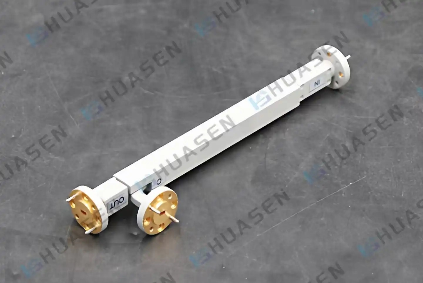
How to Test Coupling Accuracy of a Directional Coupler at Millimeter Wave
To test the coupling accuracy of a directional coupler at millimeter wave frequencies, you need precise tools and a strict process. The main step is to check how well the device measures signal power at frequencies ranging from 30 GHz to 300 GHz. Engineers separate the coupled port output and compare it to the through-port signal using a vector network analyzer (VNA) set up with SOLT or TRL methods to find the real coupling factor. If the values don't match up exactly, it could be because of manufacturing tolerances or temperature drift. This measurement has a direct effect on how reliable systems are in 5G base stations, satellite uplinks, and radar in space.VIEW MORE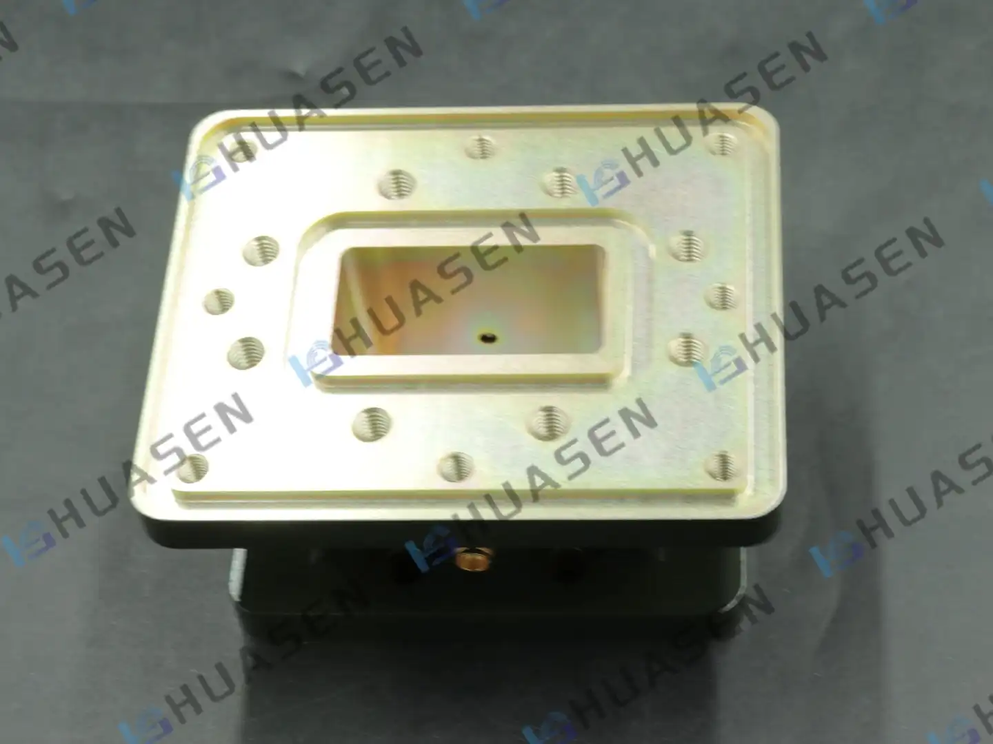
Applications of Waveguide Window in Radar & Satellite Systems
Waveguide Windows are hermetic sealing parts that let radio frequency (RF) and microwave energy travel through a transmission line while keeping different environmental areas separate. These parts keep the integrity of signals in radar and satellite systems and keep sensitive equipment safe from things like moisture, dust, pressure differences, and other things that could damage performance or cause catastrophic failure. Waveguide Windows solve important operational problems by blocking electromagnetic waves. They keep dielectric breakdown from happening in high-power transmitters, allow pressurization for altitude compensation, and ensure mission reliability in defense, aerospace, and telecommunications infrastructures.VIEW MORE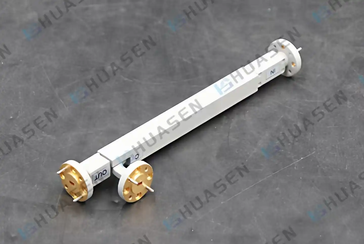
Directivity Coupler Comparison: Microstrip vs Coaxial Designs
Your RF system's signal quality, Directivity Coupler, depends on which microstrip or coaxial Directivity Coupler you choose. Microstrip designs work best in small, high-frequency PCB-based applications because they offer great performance with a small footprint. Coaxial couplers, on the other hand, are better at handling power and being resistant to environmental damage for radar, satellite, and telecommunications equipment that is placed in the field. The best way to choose components for 5G networks, aircraft sensors, and lab test equipment is to understand their unique electrical properties, such as their directivity figures, insertion loss profiles, and frequency stability, as well as their mechanical and purchasing aspects.VIEW MORE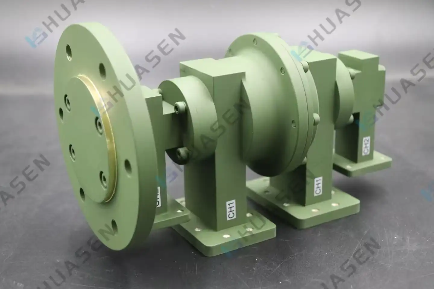
Can a Dual Channel Rotary Joint Handle High Power RF Signals?
A dual-channel rotary joint can handle high-power RF data as long as it is designed and chosen correctly for the job. These high-tech electromechanical devices are made to send two separate high-frequency signals through rotating connections while keeping the purity of the signals even when the power is very high. Modern dual-channel rotary joints are made with precise materials, better heat management, and better electrical paths that let them handle high power levels without arcing, signal degradation, or mechanical failure. When used in radar systems, satellite stations, and defense applications, these parts successfully handle high-power pulses and continuous wave transmissions. This makes them essential for mission-critical RF infrastructure that can't afford to lose performance.VIEW MORE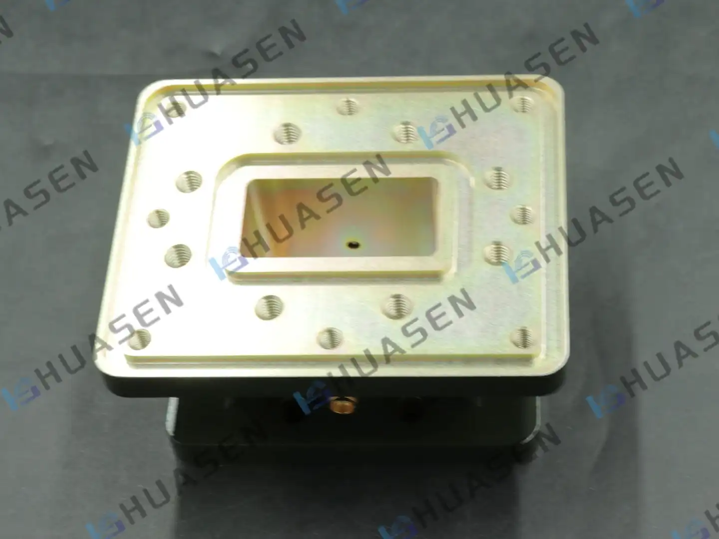
Understanding Waveguide Window Function & Material Selection
Waveguide Windows are important passive microwave parts that keep high-frequency transmission systems hermetically sealed while letting electromagnetic energy pass through with little loss. As clear RF barriers, these parts separate controlled or forced atmospheres from the outside world. This keeps sensitive equipment safe from wetness, contaminants, and changes in pressure without lowering the signal quality. The smart placement of these components in waveguide assemblies solves important engineering problems in radar, satellite communications, and base station infrastructure, where dependability has a direct effect on mission success and operating stability.VIEW MORE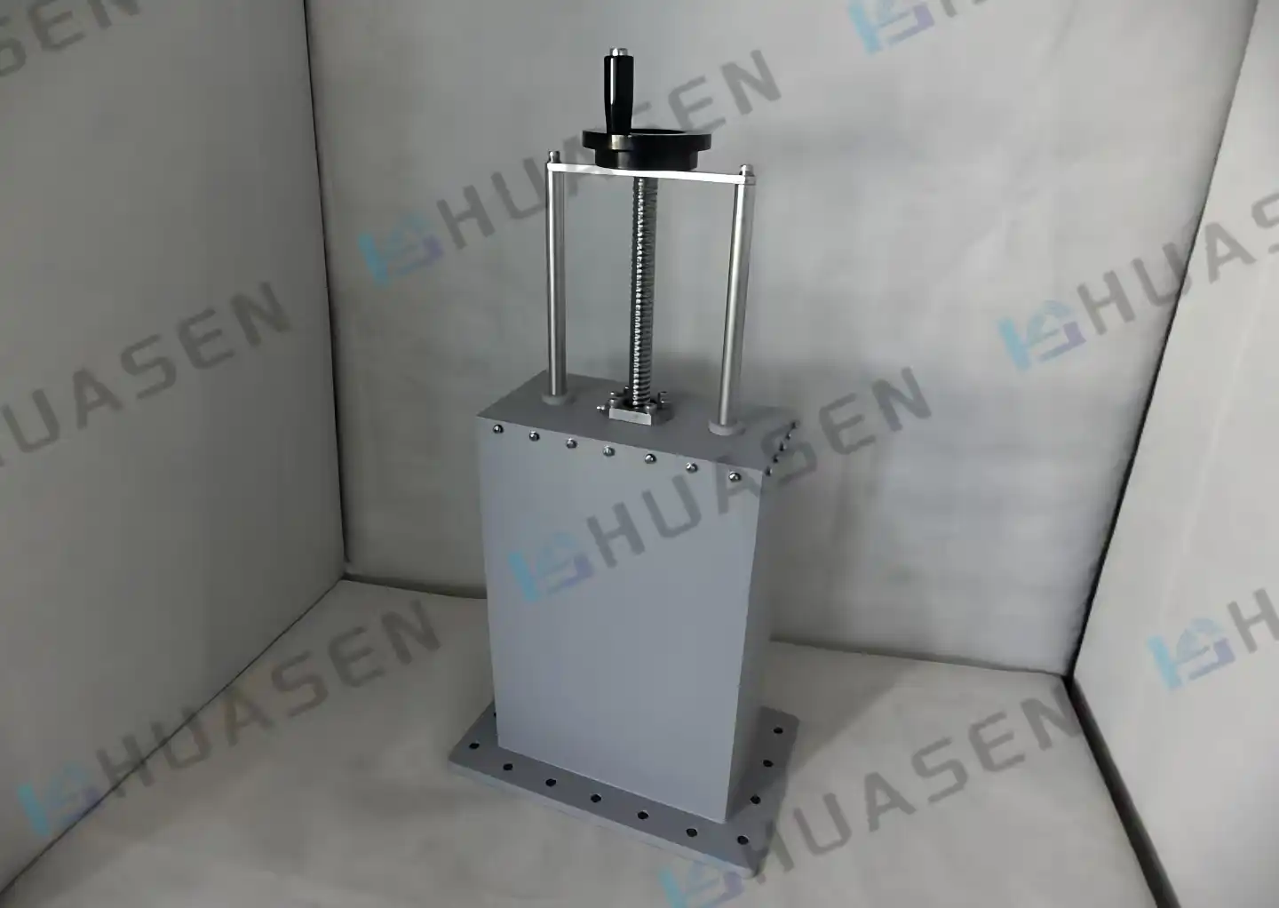
How Waveguide Sliding Short Works in Impedance Matching
A Waveguide Sliding Short works by carefully moving a conductive slide along a waveguide transmission line. This changes the phase at which electromagnetic waves bounce. Engineers can actively tune impedance with this system, getting rid of mismatches that hurt signal quality. The Huasen Microwave Waveguide Sliding Short has VSWR ≥50 and works well for reflections across a wide frequency range, from 0.32 GHz to 112 GHz. This makes it an essential part of calibration and RF testing.VIEW MORE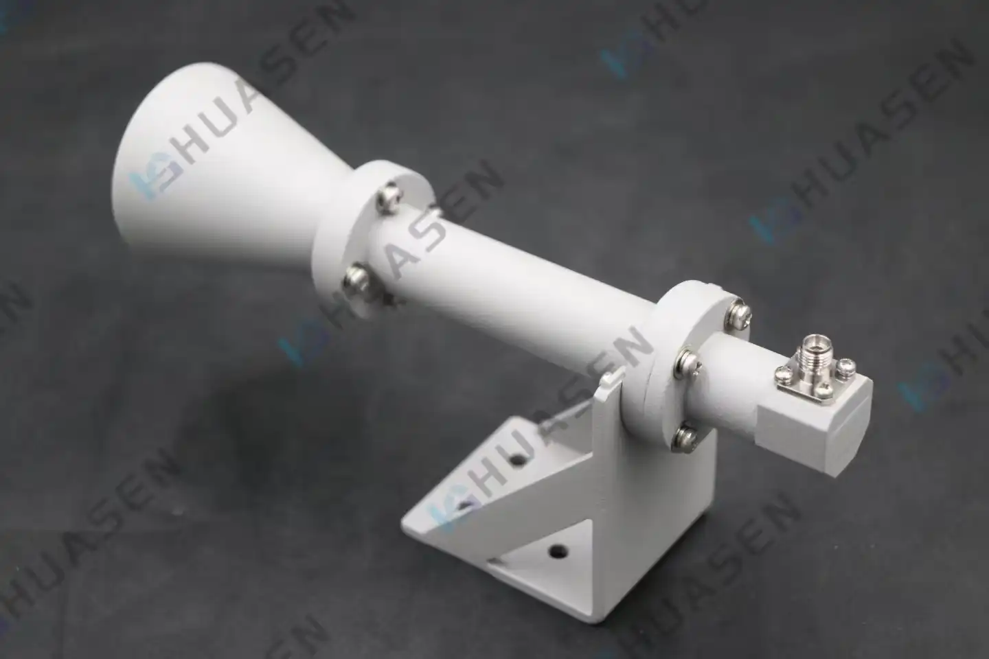
Circularly Polarized Horn Antenna Construction and Key Components
When engineers design antenna systems for mission-critical satellite links, radar sites, or aerospace platforms, they often have to deal with the problem of keeping the signal strong when the sender and receiver orientations change without warning. This problem can be fixed by a Circularly Polarized Horn Antenna, Circularly Polarized Horn Antenna which sends out electromagnetic waves in which the electric field vector continuously turns in a circle, either to the right or to the left. This turn makes it possible for the antenna to keep communicating reliably even if the terminals are not physically lined up. This makes it essential for a wide range of tasks, from tracking LEO satellites to testing 5G base stations. Successful deployments are distinguished from expensive retrofits by an understanding of the internal design and component decisions that enable this performance.VIEW MORE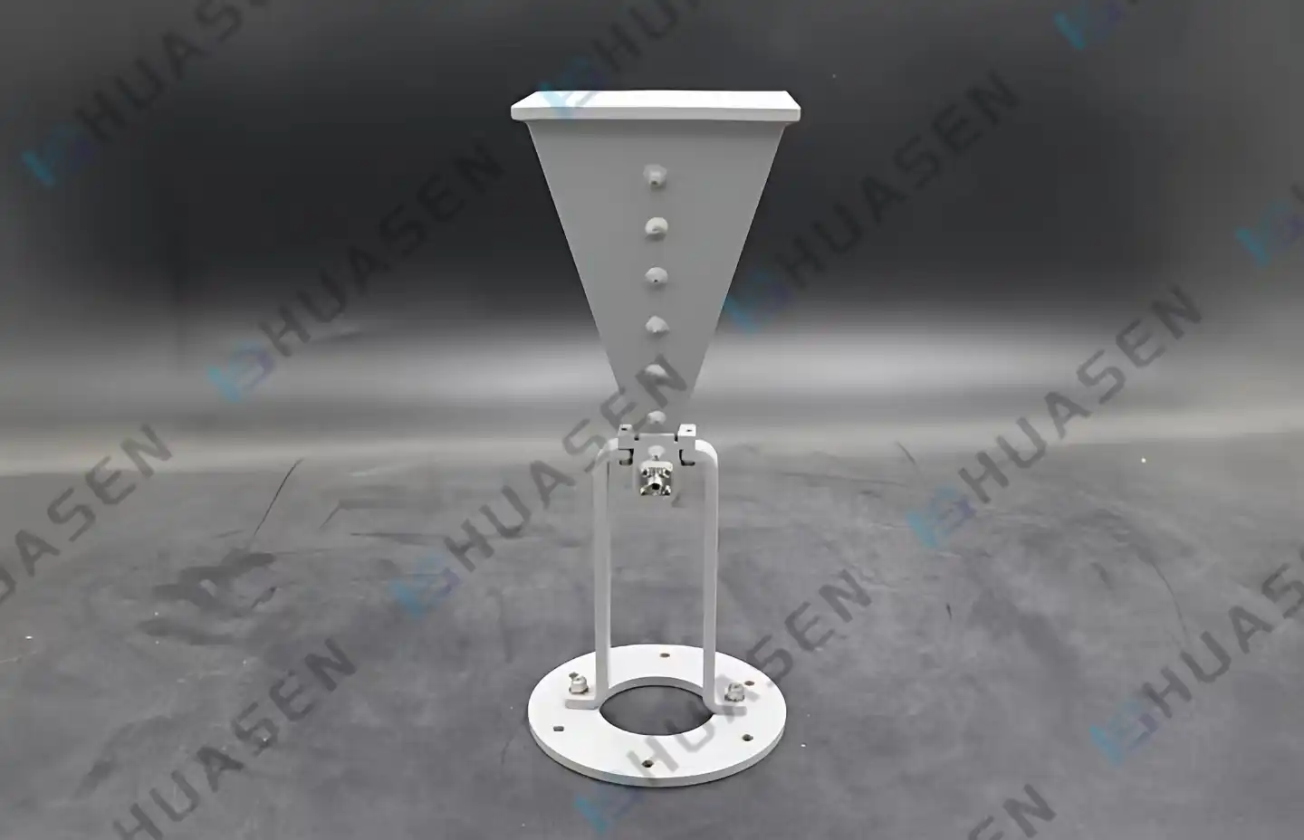
Broadband Horn Antenna Trends in RF Test and Measurement
There is a big change happening in RF test and measurement that is moving toward multi-octave testing options. Broadband horn antennas are at the front of this change. These flexible tools let engineers do full electromagnetic compatibility tests, antenna pattern characterization, Broadband Horn Antenna, and radar cross-section analysis over very wide frequency ranges—often from 1 GHz to 40 GHz or even higher—without having to switch between narrowband devices, which can cause operational delays and calibration uncertainties. As 5G networks get better and research into 6G speeds up, system integrators, defense contractors, and research labs need antennas that offer stable gain, predictable polarization behavior, and high signal integrity across multiple communication bands more than ever.VIEW MORE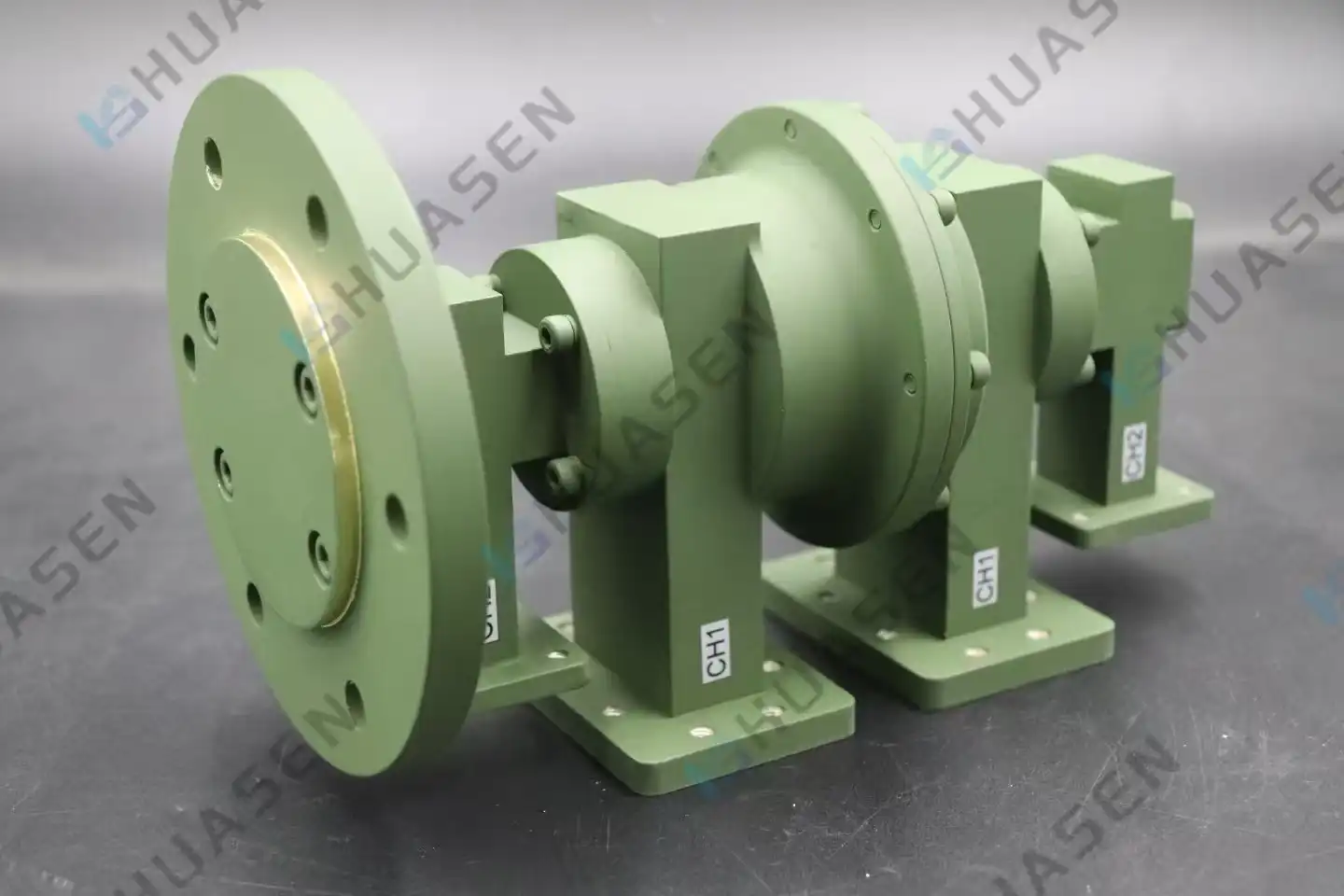
Dual Channel Rotary Joint vs Coaxial Rotary Joint: Key Differences
It's hard for engineers to decide between coaxial rotary joints and dual-channel rotary joints when they need to use rotary joint technology for radar or tracking antennas. The chief change is how the signs are sent. Two-channel rotor joints, i.e., dual-channel rotary joints, let two different data lines move at the same time. This lets each channel work at its own frequency. In coaxial devices, RF data are sent along a single line by stacking wires on top of each other. This simple difference changes how much data can be used, how well separation works, and how the system can connect with itself. As long as you know these changes, you can pick the best parts for 5G networks, satellite phones, and tracking stations at sea.VIEW MORE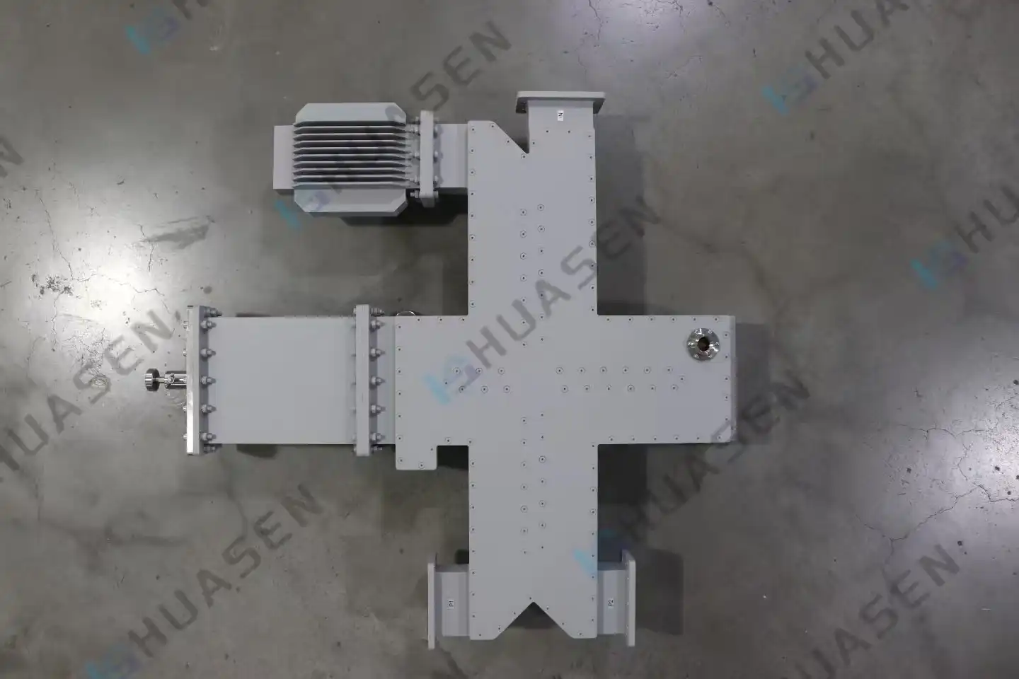
Waveguide Power Divider vs Coaxial Power Divider: Which Should You Choose
Which waveguide or coaxial power splitter you choose depends on the needs of your application. In places with a lot of power and high frequency, where insertion loss is very important, waveguide power dividers work very well. Examples include millimeter-wave radar systems, satellite ground stations, and 5G massive MIMO arrays. For setups with lower frequencies or limited area, coaxial divides are flexible, small, and cost-effective. Waveguide technology is better if your project needs to handle a lot of power above 20 GHz with little signal loss. Coaxial systems are useful for providing internet service below 18 GHz and are easy to integrate. Engineers can choose the best components by understanding these basic trade-offs.VIEW MORE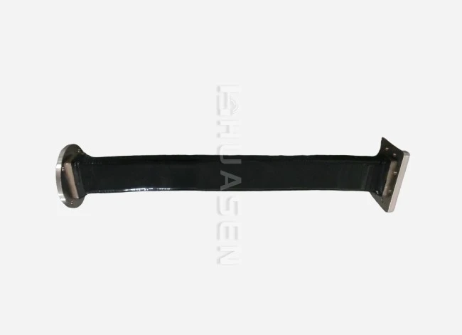
Benefits of Flex Waveguide in Complex RF Installations
There are times when fixed waveguide designs don't work well with complex RF systems, such as those in satellite ground stations, radar platforms in the air, or communication networks. Now is the time when flexible waveguide (flex waveguide) and bent waveguide technology come in handy. These parts were carefully made so that they are physically flexible and still work very well electrically. This lets RF engineers handle issues like misalignment, shaking loads, and temperature changes that would usually hurt the stability of the signal. By making your system with flexible waveguide assemblies, you can avoid catastrophic flange failures, speed up installation, and make sure long-term dependability in places where hard plumbing can't handle the demands of everyday use.VIEW MORE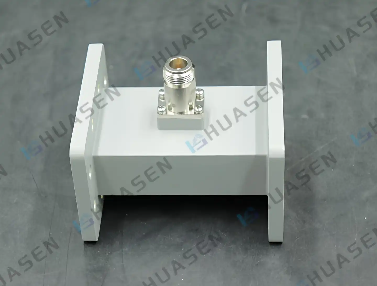
Waveguide Probe Coupler Selection Guide for Aerospace Applications
Selecting the right waveguide probe coupler for aerospace applications demands meticulous attention to environmental resilience, signal integrity, and mechanical compatibility. Aerospace systems—from satellite transponders to radar installations on UAVs—operate under extreme thermal cycling, vibration loads, and vacuum conditions where component failure is not an option. Engineers must evaluate coupling range, directionality specifications, insertion loss budgets, and connector interface standards while ensuring compliance with MIL-STD-202 and outgassing requirements per ASTM E595. This guide walks through critical selection parameters to help system integrators specify couplers that deliver reliable performance throughout mission lifecycles.VIEW MORE
- 1
- 25
- 26
- 27
- 28
- 29
- 60
