
Home / Blog
Blog
0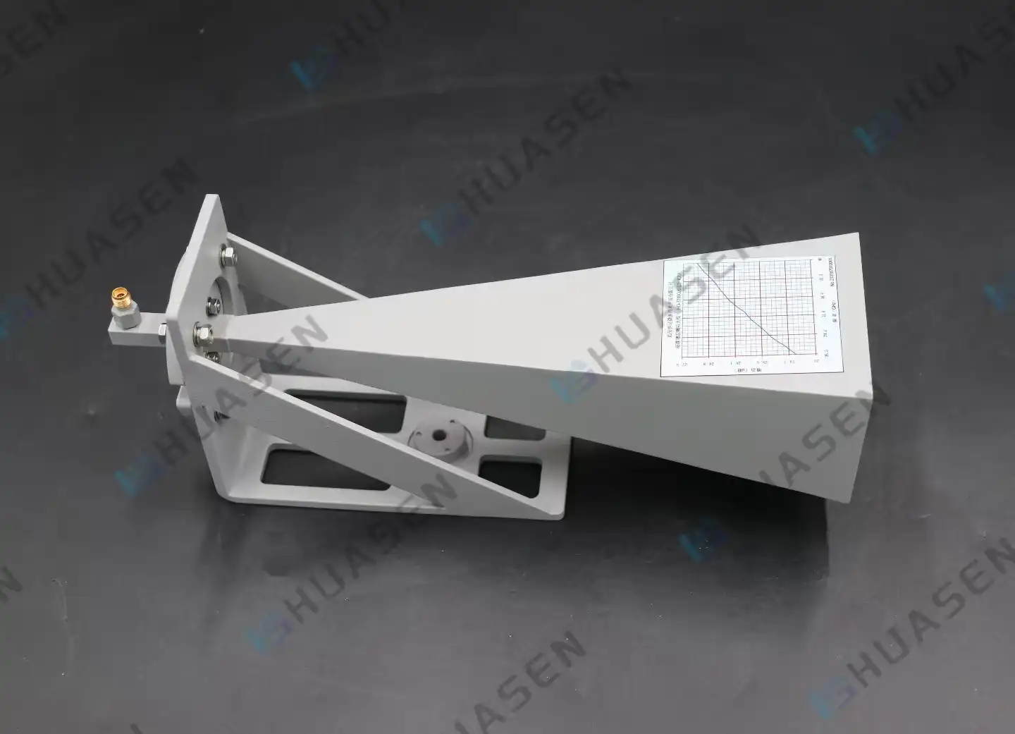
How to Test standard gain horn antenna Gain in Labs
Laboratory gain testing on a standard gain horn antenna requires precise RF measuring methods, such as replacement or comparison against calibrated reference antennas. These horn antennas are metrological benchmarks because their gain can be estimated theoretically and tested experimentally. System integration and compliance testing need accurate far-field distance computation, calibrated network analysers, and regulated anechoic chamber conditions to reduce measurement error and assure consistent, traceable findings.VIEW MORE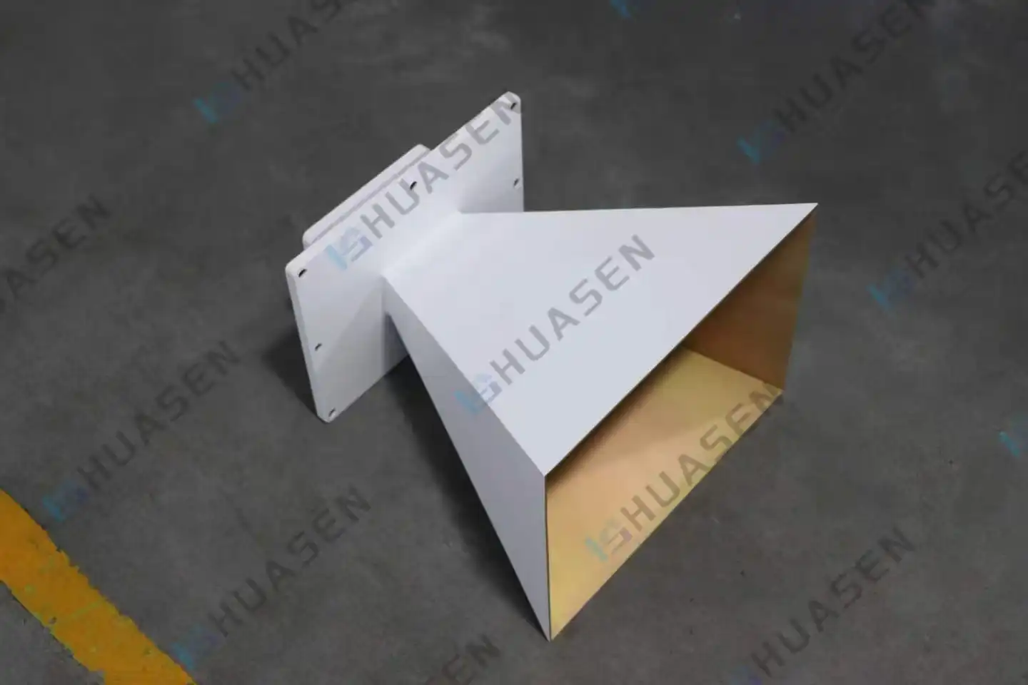
Pyramidal Horn Antenna vs Conical Horn: Technical Review
Procurement teams must choose between pyramidal horn antennas and conical horn antennas for demanding RF applications. Pyramidal horn antennas' rectangular waveguide-fed construction of pyramidal horn antennas provides high directivity for polarisation-sensitive tests and EMC testing. Conical horns' circular symmetry makes them ideal for broadband applications that need constant radiation patterns across frequency ranges. Understanding these basic distinctions influences base station architecture, satellite ground terminal, and laboratory calibration procurement choices.VIEW MORE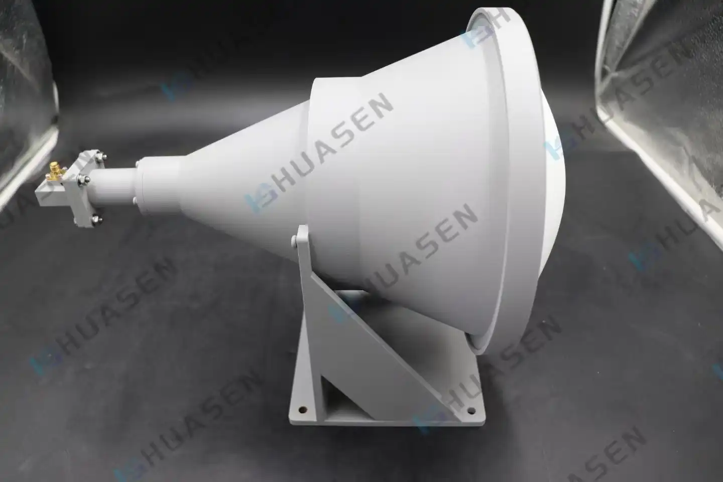
Lens Horn Antenna vs Standard Horn: Technical Comparison
Performance trade-offs must be considered when choosing a lens horn antenna or a regular horn antenna for high-frequency communication systems. Lens horn antennas use precision dielectric lenses to transform spherical wavefronts into planar phase distributions, decreasing phase error and allowing compact high-gain systems. Standard horns are mechanically simpler and cheaper, but their flared waveguide design restricts gain efficiency in small arrangements. Space-constrained 5G backhaul, satellite ground stations, and radar test ranges struggle to maintain excellent directivity without unnecessary length. The lens-enhanced solution solves this problem.VIEW MORE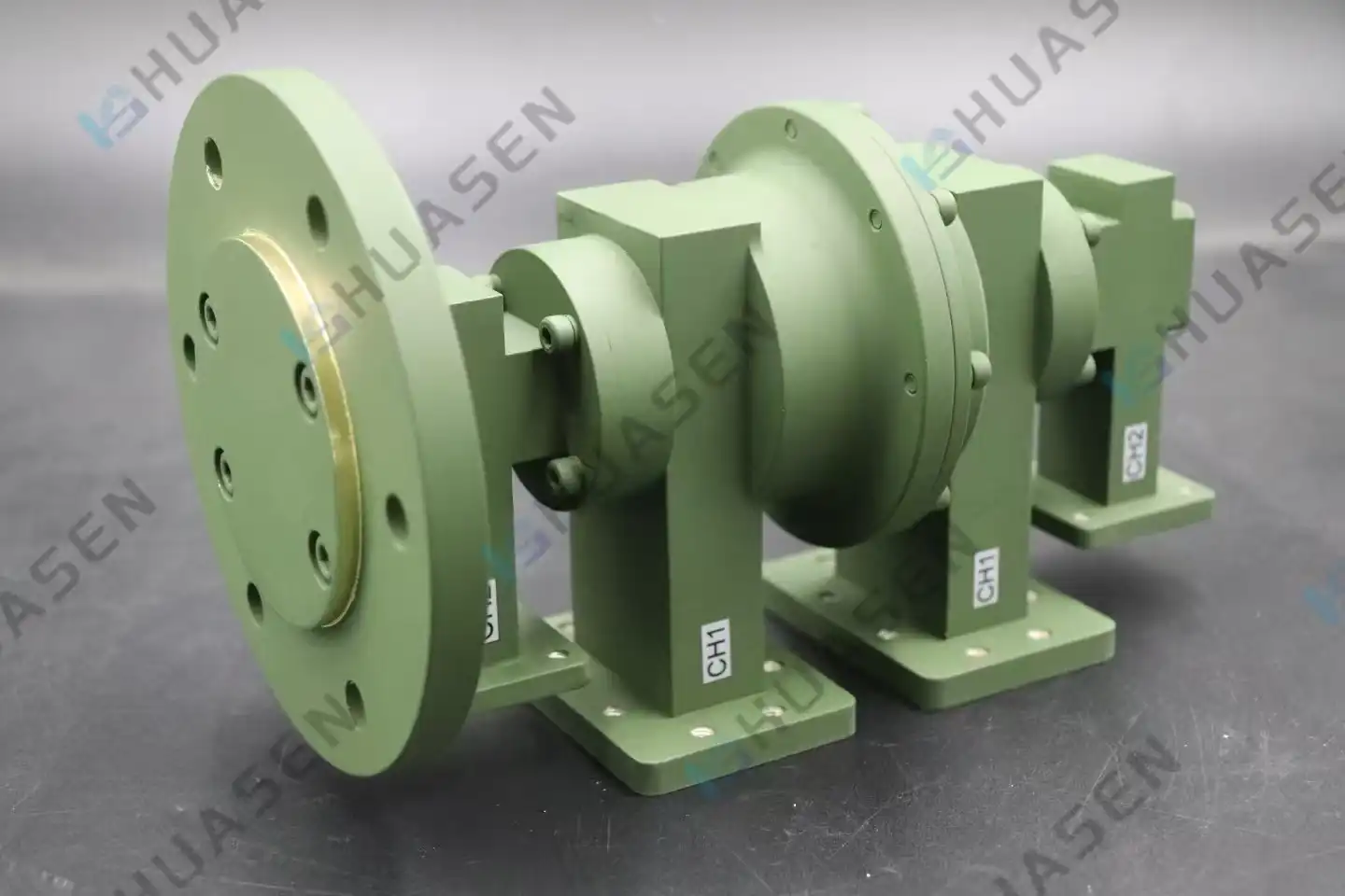
How to Select a Dual Channel Rotary Joint for Aerospace Systems
When choosing the right dual-channel rotary joint for aircraft systems, you need to pay close attention to the frequency range, power handling, rotary life, and how well it can handle the environment. These RF transmission devices allow a constant rotation of 360 degrees while keeping the signal strong across two separate channels. This is very important for radar pedestals, satellite tracking antennas, and test tools for avionics. Engineers in the aerospace industry have to find a balance between electrical performance measures like VSWR and mechanical longevity. They have to make sure that the part can handle high and low temperatures, vibration, and changes in altitude without affecting the accuracy of tracking or mission-critical messages.VIEW MORE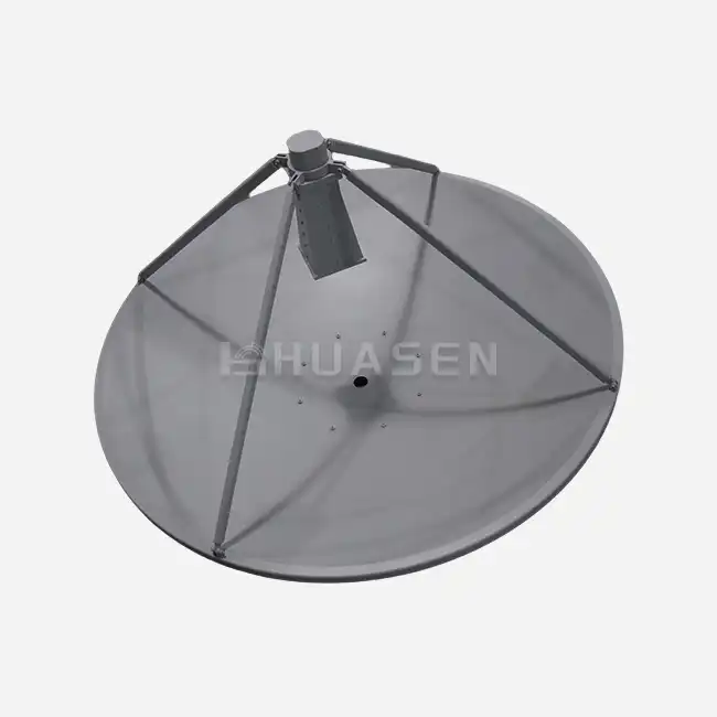
Why Parabolic Antenna Is Preferred for Long-Distance Links?
Parabolic antennas are always the best choice for engineering teams trying to communicate over tens of kilometres between remote base stations, satellite ground stations, or offshore platforms. These reflector-based devices circumvent free-space route loss that weakens signal power over long distances by concentrating radio frequency energy into small, highly focused beams. These antennas boost transmission power and receiver sensitivity by focusing electromagnetic waves to a single feed point using an accurate parabolic shape. Long-haul wireless networks' key issue is sustaining signal-to-noise ratio despite air attenuation and distance-related losses that would render other antenna designs useless.VIEW MORE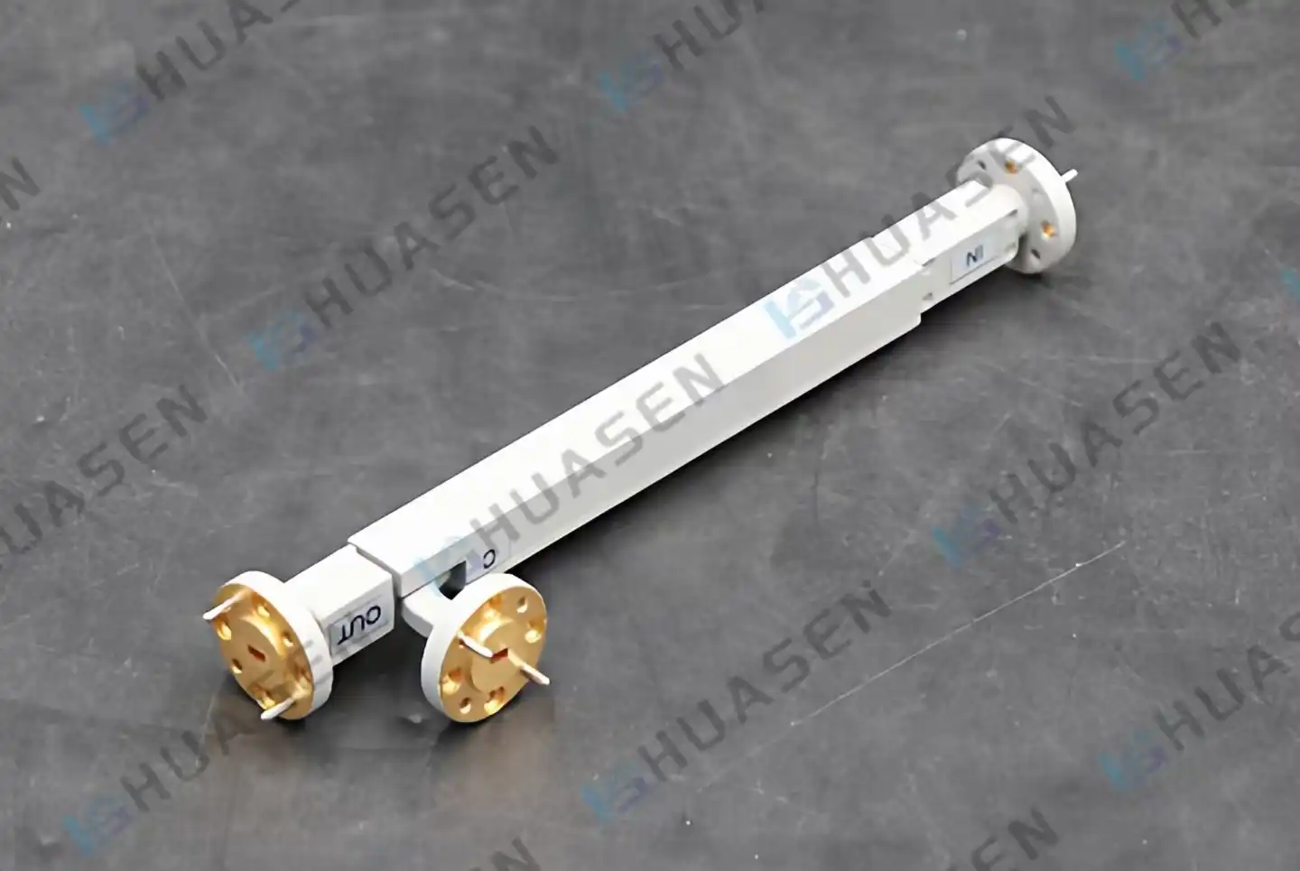
Choosing the Right Directional Coupler for Aerospace and Defense
Selecting the appropriate directional coupler for aerospace and defense applications hinges on balancing critical performance parameters with operational reliability. A well-chosen directional coupler enables accurate signal sampling and power monitoring without disrupting the main RF transmission path. This decision influences system precision, mission integrity, and long-term operational costs. Engineers and procurement professionals must evaluate coupling factors, directivity levels, insertion loss, and environmental resilience to match components with demanding radar, satellite, and communication system requirements.VIEW MORE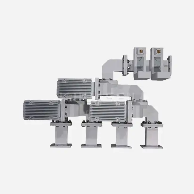
Design Considerations for Miniaturized RF Combiners in RF Test Devices
When making advanced RF test tools, the RF combiner is often the part that affects how well the whole system works. This passive device combines several signal lines into a single output. This lets engineers test multichannel performance without taking up valuable bench space. In labs where rack space is limited and in the field where movable test rigs are needed, tiny combiners have become essential. They keep the integrity of the signal over a wide range of bandwidths and meet the strict standards for insertion loss and thermal stability needed for 5G testing, satellite ground station calibration, and radar component evaluation.VIEW MORE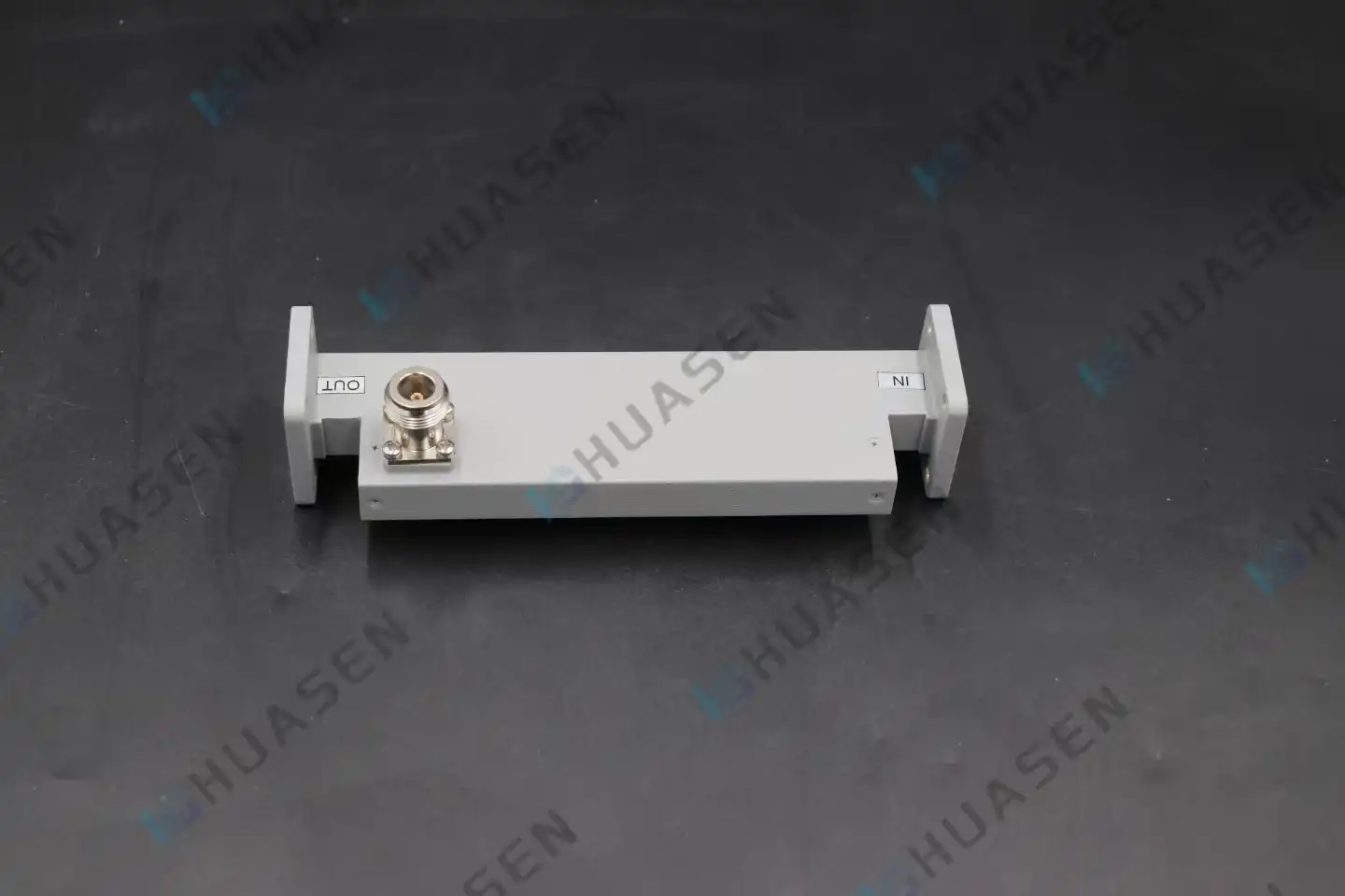
How to Calculate Directivity in a Directivity Coupler
The logarithmic measure of isolation (the attenuation from the input to the isolated port) and coupling factor (the energy removed to the coupled port) are used to figure out the directivity of a directivity coupler. Mathematically, Directivity (dB) = Isolation (dB) - Coupling Factor (dB). This measure shows how well the device can tell the difference between forward power and mirrored power. Accurate directivity calculation is needed for precise RF testing situations like radar calibration, 5G base station verification, and satellite upload tracking to make sure the measurements are correct. Engineers use network analyzers to measure S-parameters (S31 for coupling and S32 for isolation) over a range of operating frequencies. They then subtract these values to make sure the coupler meets the standards, which are usually more than 40dB for metrology-grade applications.VIEW MORE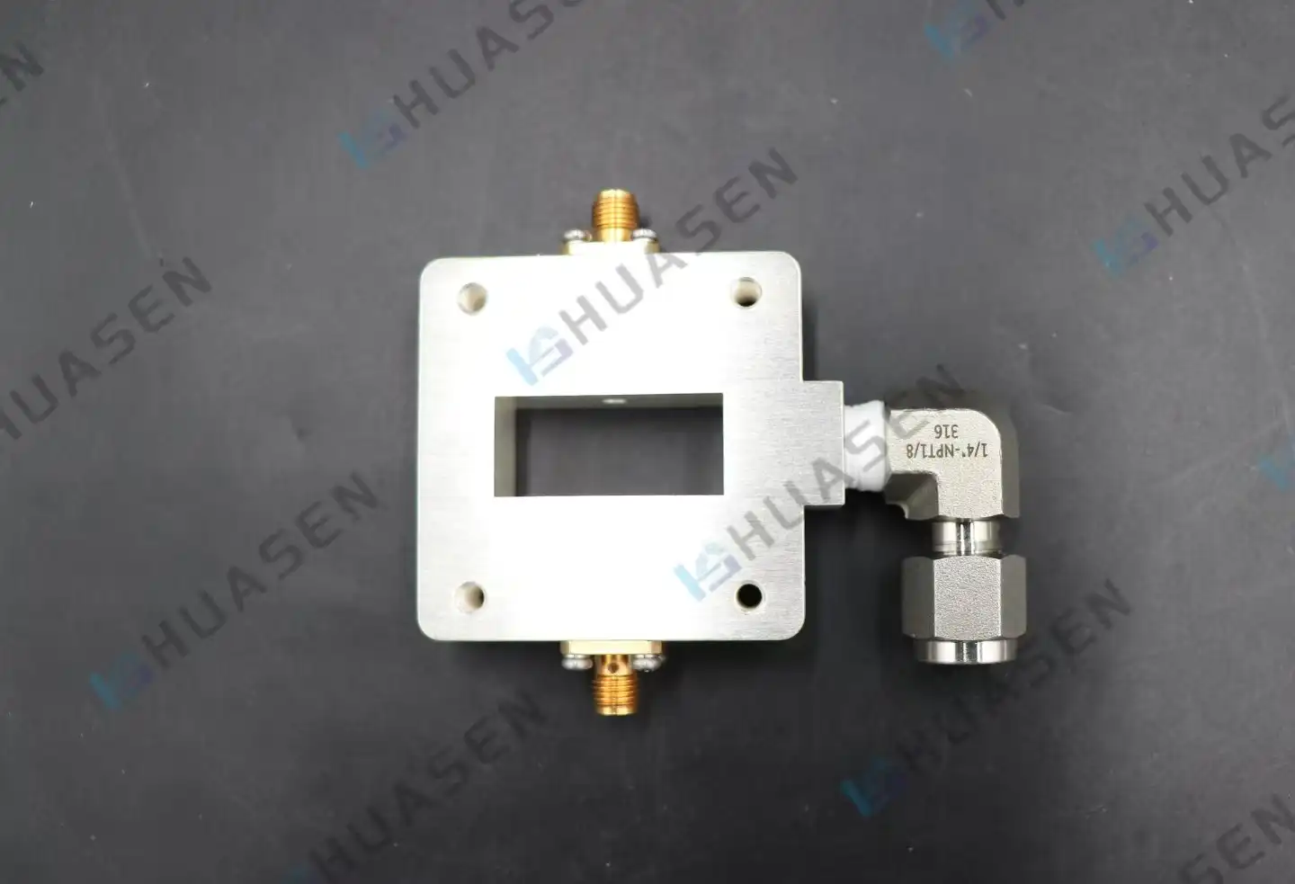
Waveguide Probe Coupler Performance Testing for RF and Radar Systems
Waveguide probe couplers need to be tested for performance to make sure they work reliably in RF and radar systems, where signal integrity directly affects mission-critical uses. As the electromagnetic bridge between coaxial transmission lines and waveguide structures, these precise components need to be thoroughly tested for things like coupling accuracy, VSWR, and insertion loss. Engineers can find impedance mismatches and signal degradation before putting a system into use by following the right testing methods. This protects system performance in areas like defense, aircraft, and telecommunications, where even small losses can make operations less effective.VIEW MORE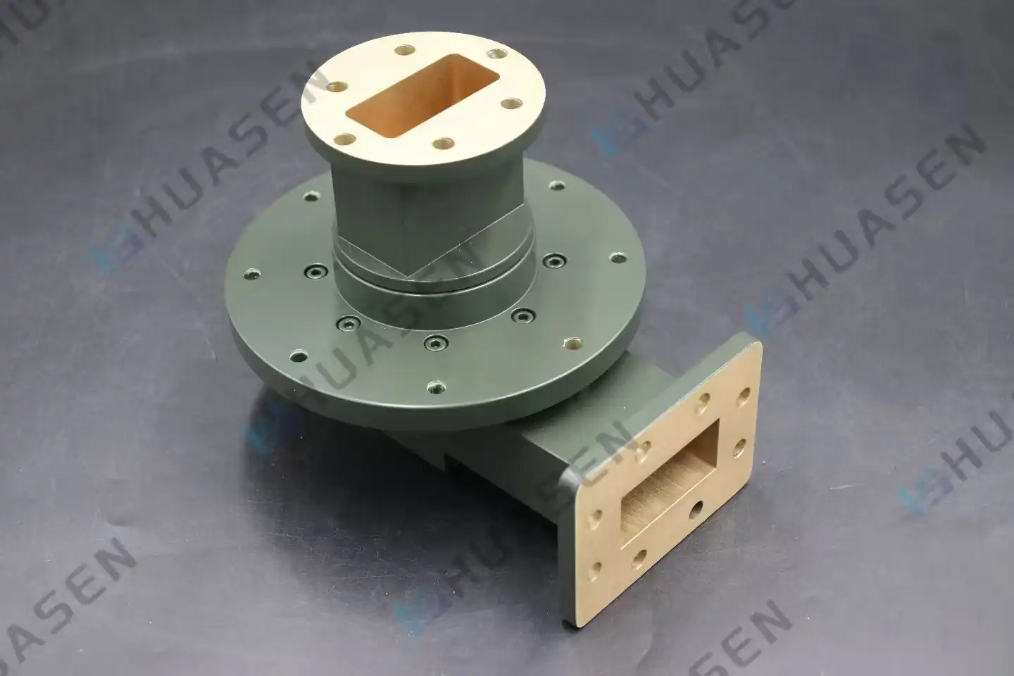
What Is a Waveguide Rotary Joint and Why It Matters in Radar Systems
A waveguide rotary joint is a precise electronic part that lets high-frequency radio frequency (RF) and microwave signals flow smoothly between structures that are still and structures that are moving. It is used in radar and communication systems. This device solves a basic problem: how to keep the signal strong while letting the wire rotate 360 degrees without damaging the signal or bending the cable. In radar applications where antennas need to scan all the time, these joints get rid of mechanical problems while keeping the electromagnetic performance high across important frequency ranges. Their importance comes from the fact that they allow effective operation in harsh settings where both mechanical durability and electrical accuracy are essential.VIEW MORE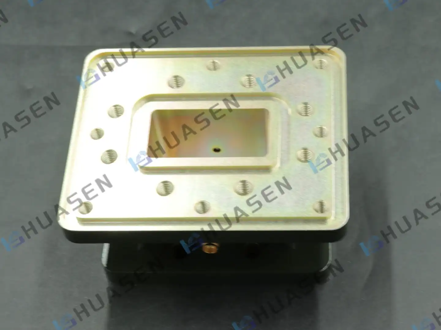
Waveguide Window Design for High-Frequency RF & Microwaves
Waveguide window design is a tricky mix of electromagnetic theory and mechanical engineering. It solves the problem of keeping signals pure in high-frequency RF and microwave systems while also keeping the surroundings separate. Because these parts are clear, they let electromagnetic energy pass through a waveguide transmission line while keeping out wetness, contaminants, and changes in pressure. When it comes to radar sites, satellite ground stations, and defence communication networks where reliability can't be compromised, the right design has a direct effect on insertion loss, power handling capacity, and system life.VIEW MORE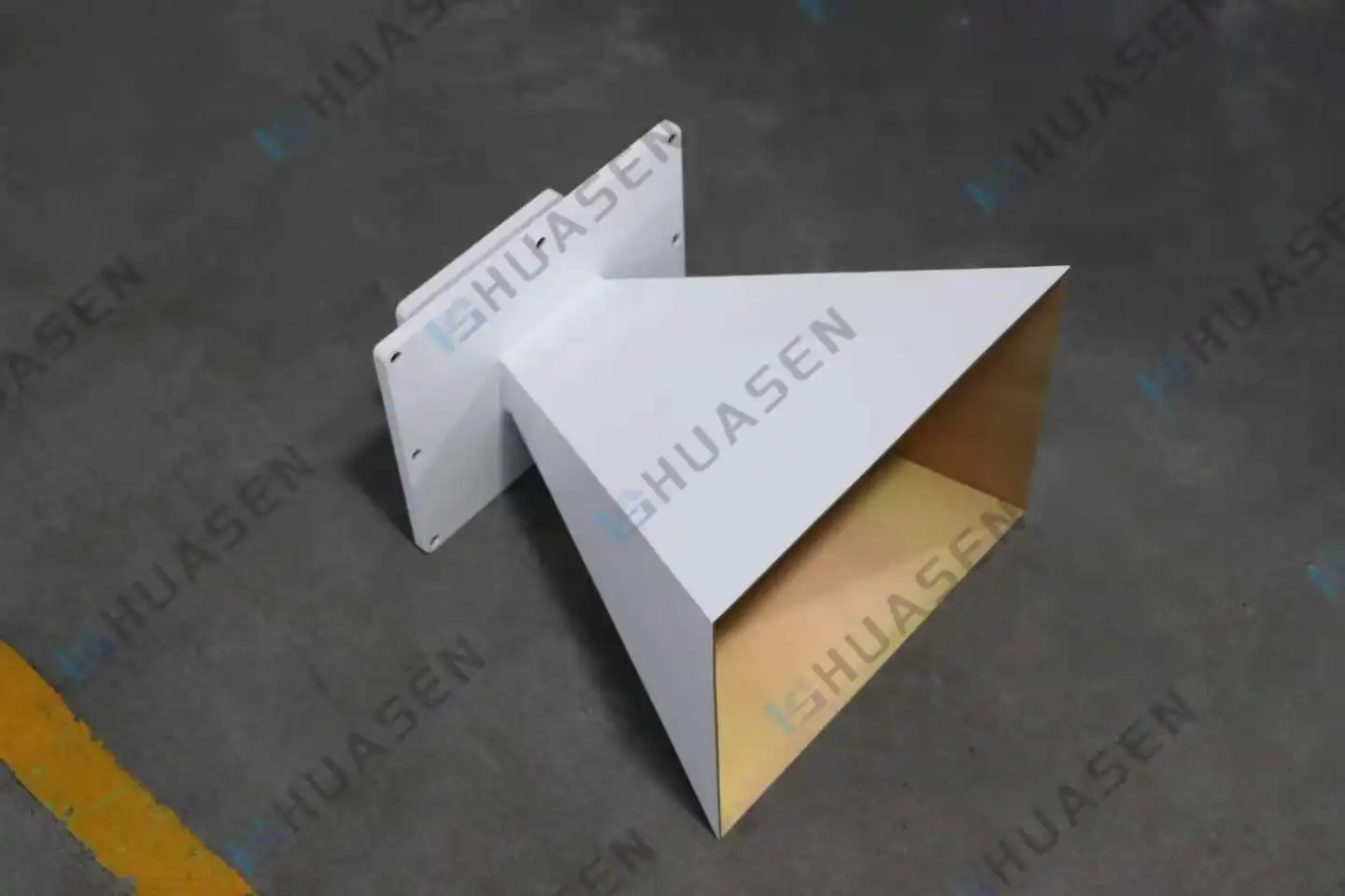
Pyramidal Horn Antenna Construction and Polarization Features
Pyramidal horn antennas provide strong energy and clear polarization, which are important for microwave and radar technologies. As impedance transformers, these precision-engineered devices eventually match the impedance of the waveguide to that of free space. This keeps signal echoes to a minimum and directivity to a maximum. Their controlled aperture design solves important problems in high-frequency transmission, which is why 5G backup systems, satellite ground stations, radar feeds, and EMC testing settings can't work without them. This guide talks about the basics of building, the properties of polarization, how things work, and how to buy things for buying managers, RF engineers, system integrators, and original equipment manufacturers (OEMs). By knowing about these scientific and practical aspects, you can make smart choices that make sure the antenna works well with the project's needs, your budget, and the delivery schedule.VIEW MORE
- 1
- 10
- 11
- 12
- 13
- 14
- 60
Total 60 pages
