
Blog
0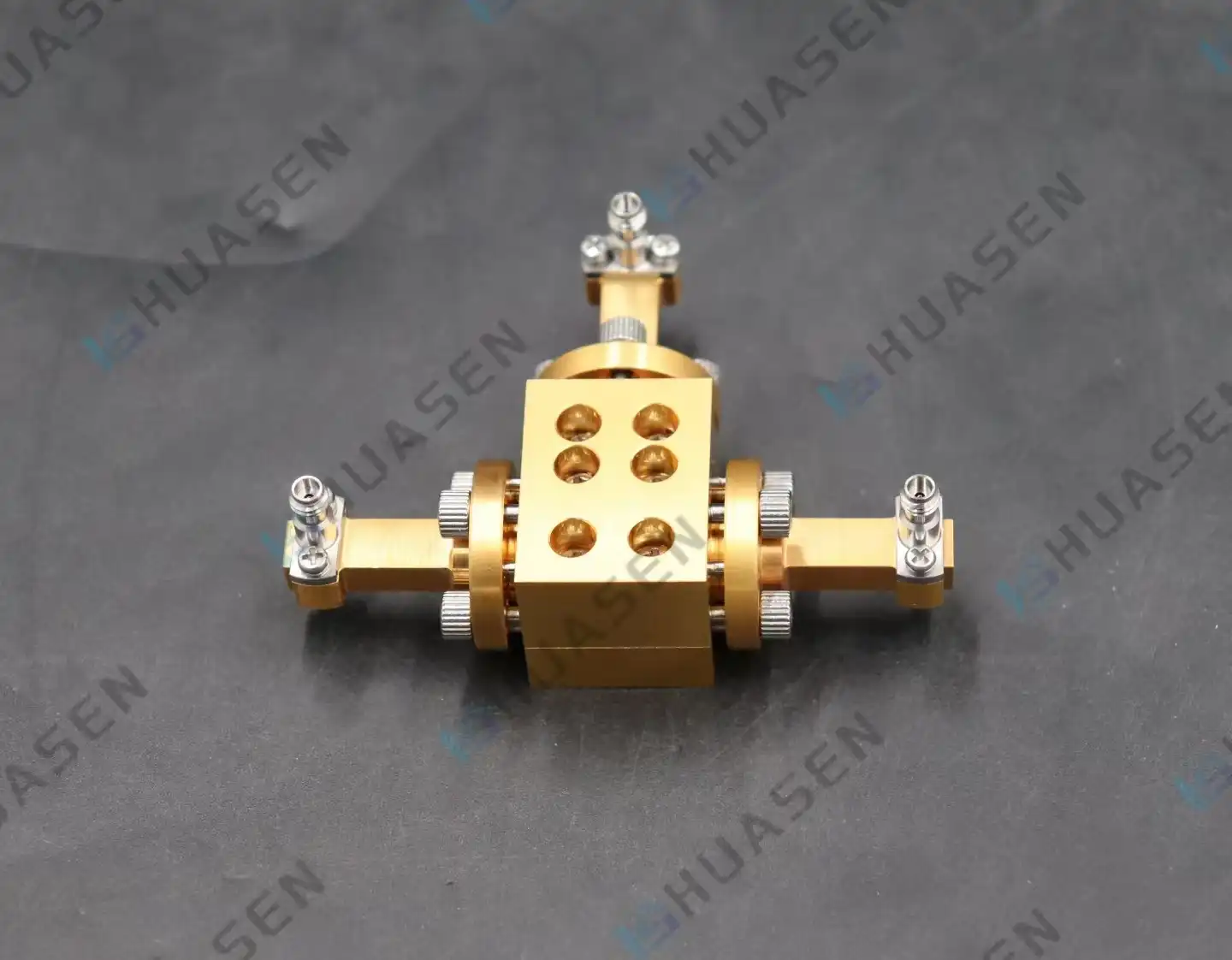
RF Combiner Solutions for Multi-Carrier Communication Networks
RF combiner options for multi-carrier communication networks are high-tech passive parts that join multiple signal routes efficiently while keeping the integrity of the signals across a wide range of frequency bands. By combining various carrier signals into a single transmission line, these important devices help network providers make the best use of the spectrum, lower the cost of equipment, and improve the reliability of the system. Modern RF combiner technology solves important problems in 5G, satellite communications, and high-power broadcasts, where signal quality and the ability to handle power directly affect how well networks work and how efficiently they run.VIEW MORE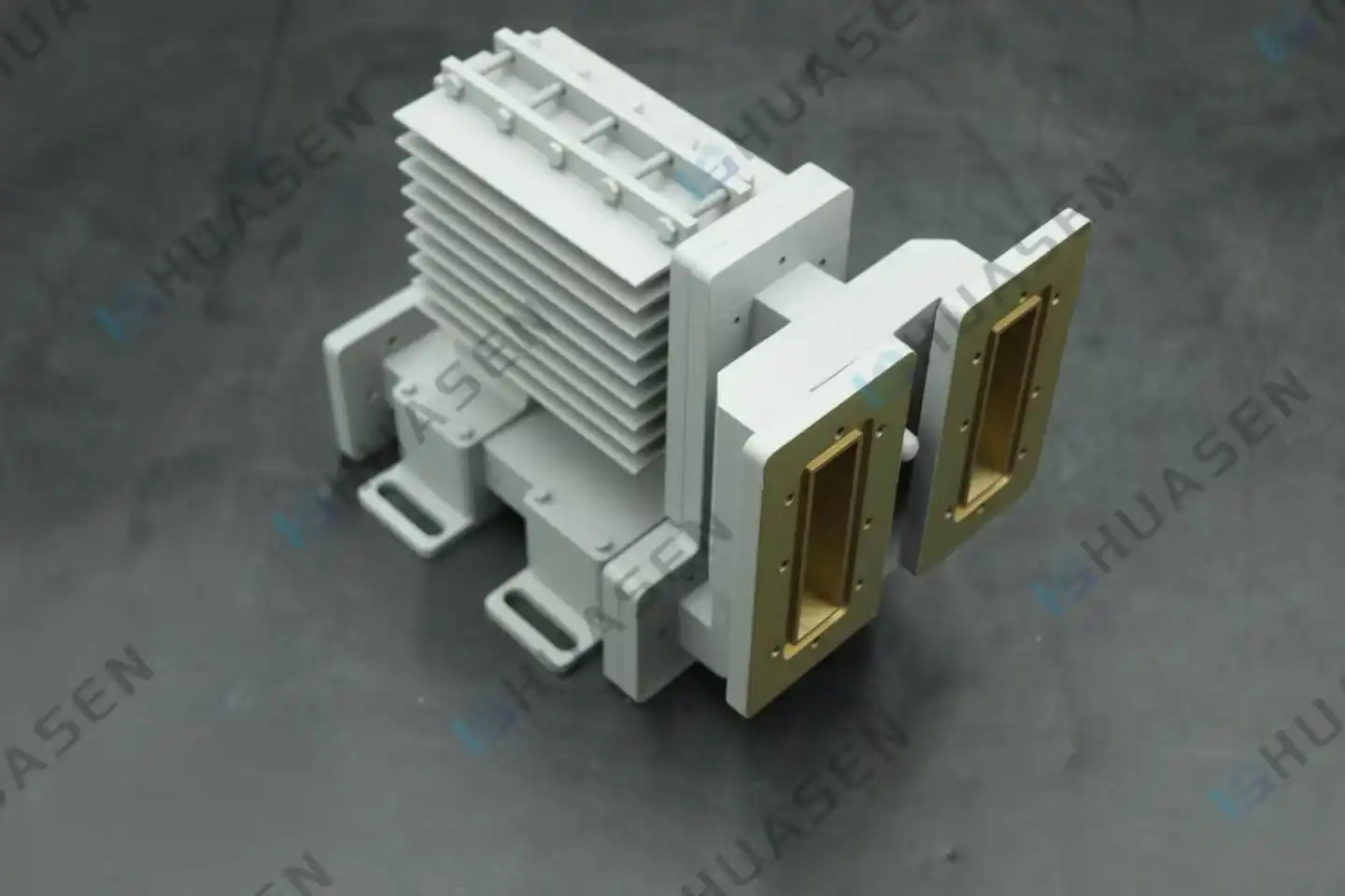
Leading Millimeter Wave RF Combiner Manufacturers for Radar Systems
The best companies that make millimeter wave RF combiners focus on making complex passive electromagnetic parts that combine several high-frequency signals into a single output for advanced radar uses. In particular, these companies focus on making RF combiners that have very low insertion loss (usually less than 0.2 dB) and high port-to-port separation (more than 30 dB). To meet the strict needs of military, automobile, and aircraft radar systems across Ka-band and beyond, the leaders in the field put thermal management, frequency stability, and environmental resistance at the top of their list of priorities.VIEW MORE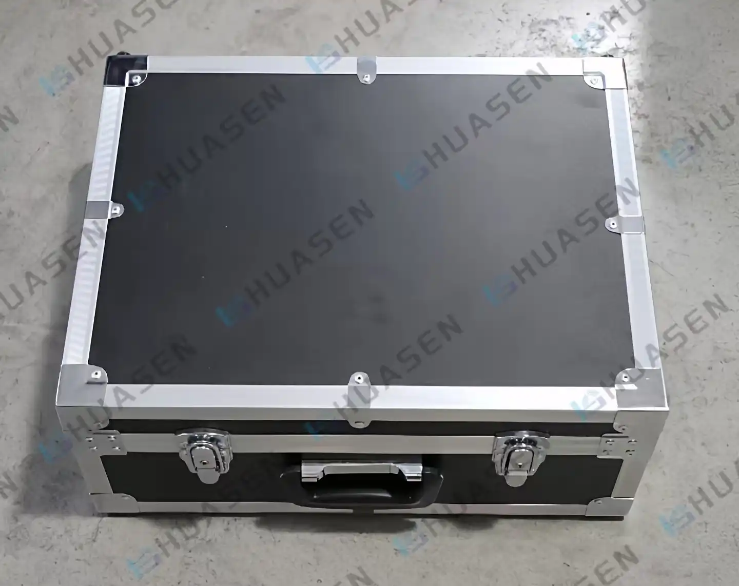
RF Test Bench Layout Optimization for Waveguide Calibration Kits
RF test bench plan optimization for waveguide calibration kits is an important part of microwave testing infrastructure that has a direct effect on the accuracy of measurements and the performance of the system. Setting up the test setting correctly is important for making sure that the vector network analyzer is calibrated correctly and that signal loss and external interference are kept to a minimum. Waveguide calibration kit parts, like precision loads, short circuits, Waveguide Calibration Kit, and transmission line standards, are placed in a way that makes it possible to take exact S-parameter readings at millimeter-wave frequencies. Layout optimization that works well cuts down on regular mistakes and improves repeatability in high-frequency testing situations.VIEW MORE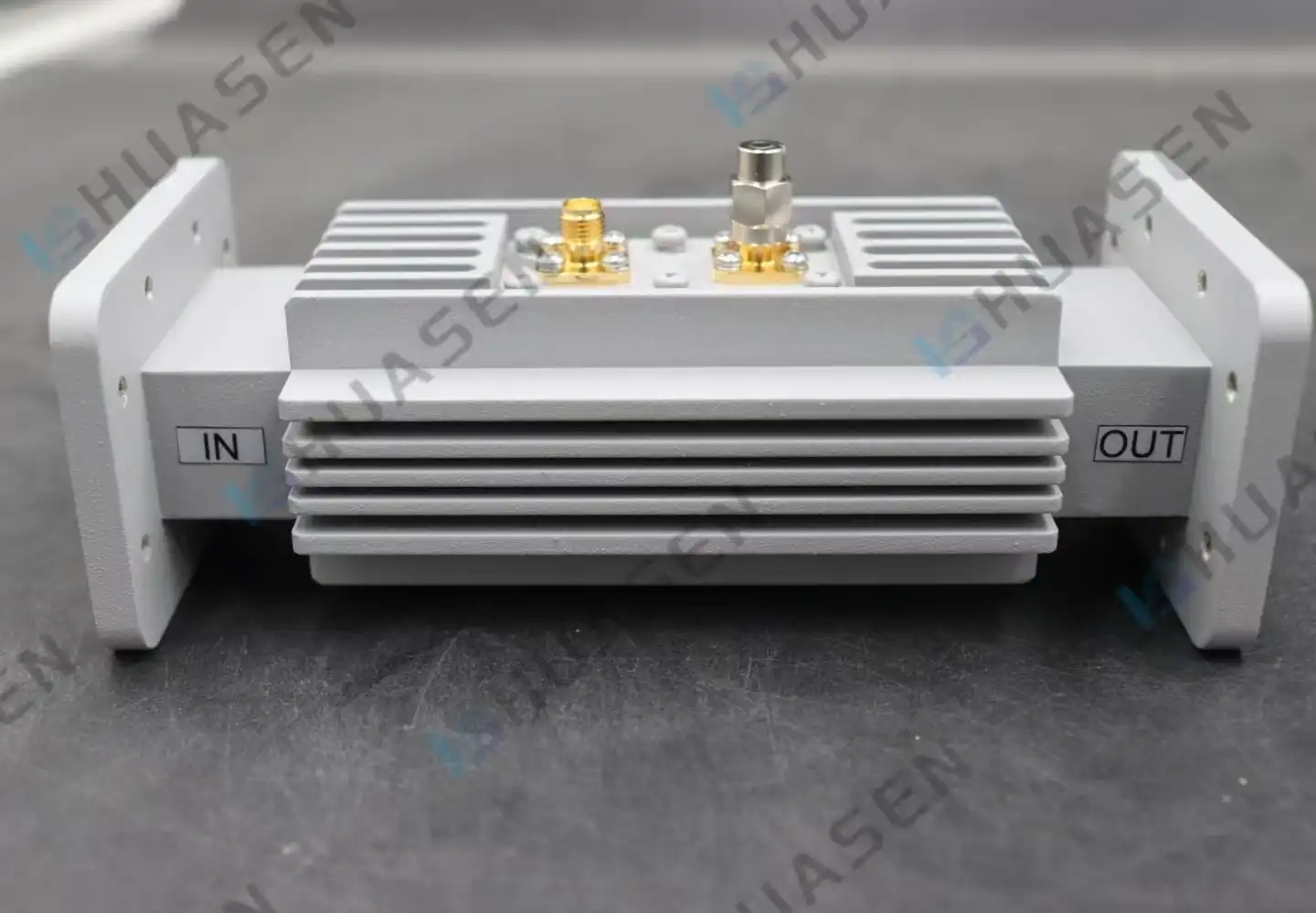
Key Design Factors of Waveguide Loop Couplers for High-Frequency Use
The best way to build a Waveguide Loop Coupler depends on specific engineering factors that have a direct effect on how well the system performs at high frequencies. Some important design factors are keeping the coupling factor stable, improving the directivity, minimizing the insertion loss, and shaping the electromagnetic field interaction. How accurate the signal sampling is and how much power it can handle depend on the loop probe design, the material choice, and how the waveguide is integrated. Advanced designs include coupling devices that can be adjusted and a wide frequency response to meet the needs of demanding industries like aircraft, radar, and telecommunications, while still being very reliable in harsh circumstances.VIEW MORE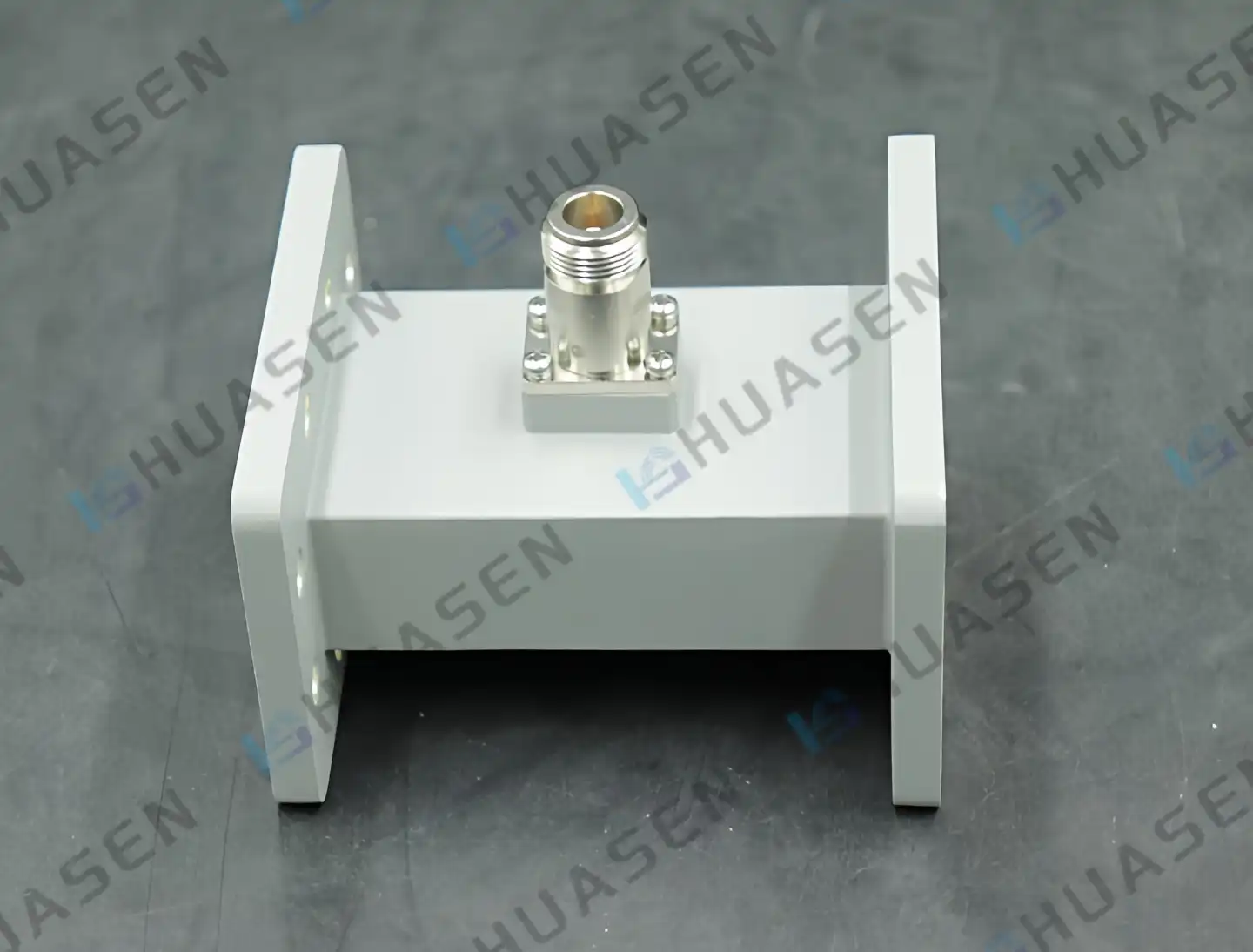
Waveguide Probe Coupler vs Waveguide Loop Coupler: Which to Choose
Choosing between a Waveguide Probe Coupler and a waveguide loop coupler mostly relies on the needs of your application, how much power you need to handle, and the limitations of your system. Waveguide Probe Couplers work great for high-frequency radar systems and satellite communications because they can precisely couple electric fields with very little insertion loss. On the other hand, loop couplers provide better isolation and magnetic field coupling, which is especially useful in complex RF testing settings and high-power tracking situations where directional coupling is very important.VIEW MORE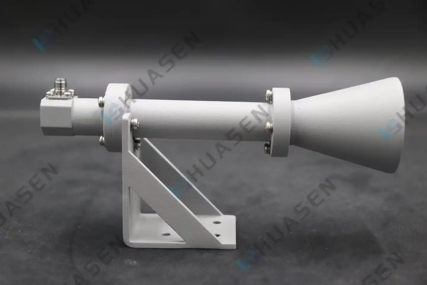
Custom Circularly Polarized Horn Antenna: What Parameters Need to Be Provided?
When specifying a custom horn antenna circular polarization solution, engineers must provide comprehensive technical parameters to ensure optimal performance. Essential specifications include operating frequency range, required axial ratio performance, gain characteristics, polarization sense (RHCP or LHCP), connector types, and environmental requirements. Additionally, power handling capabilities, bandwidth specifications, radiation pattern requirements, and mechanical constraints such as mounting configurations and dimensional limitations must be clearly defined. These parameters enable manufacturers to design precisely tailored solutions that meet stringent application demands across satellite communications, radar systems, and advanced wireless networks.VIEW MORE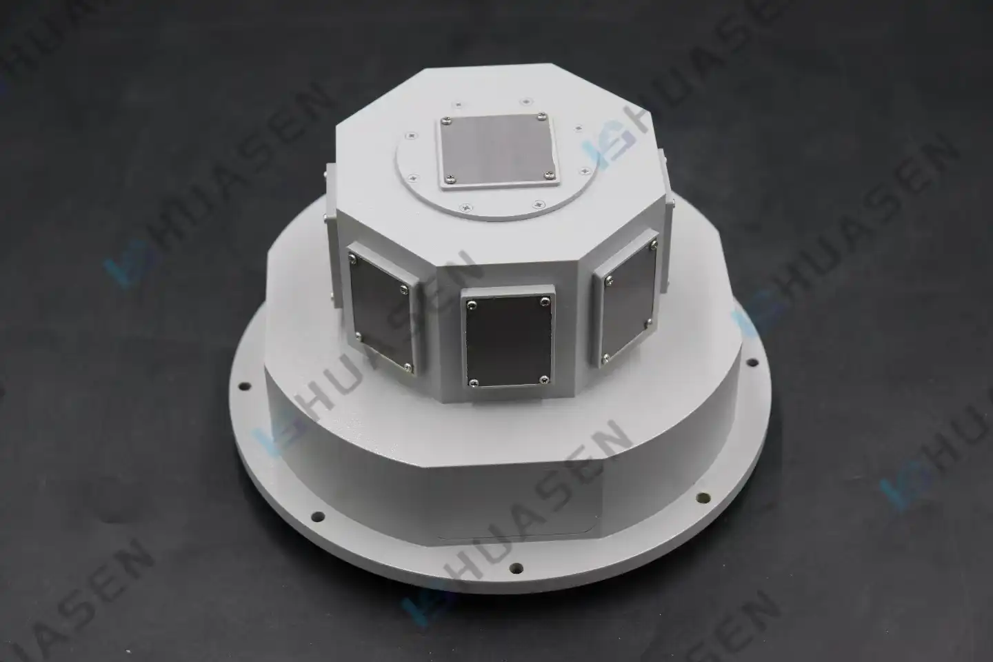
How to minimize mutual coupling in microstrip antenna arrays?
Minimizing mutual coupling in microstrip antenna arrays involves optimizing element spacing, implementing electromagnetic bandgap structures, utilizing defected ground planes, and employing proper feeding techniques. These Microstrip Antenna design strategies significantly enhance array performance by reducing electromagnetic interference between adjacent elements, improving radiation efficiency, and maintaining desired beam patterns. Advanced substrate selection and precise impedance matching also contribute to coupling reduction, ensuring optimal signal integrity in high-frequency applications.VIEW MORE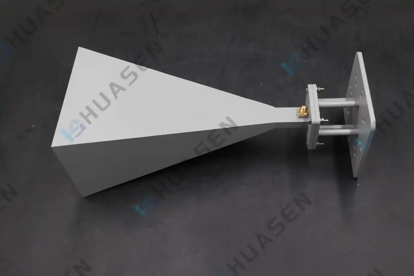
How to Determine the Phase Center of a Broadband Horn Antenna?
Determining the phase center of a broadband antenna requires systematic measurement techniques combining near-field scanning, far-field radiation pattern analysis, and electromagnetic simulation tools. The phase center represents the apparent origin point of electromagnetic radiation, which shifts with frequency in broadband horn antennas due to their complex internal geometries and wide operational bandwidth. Accurate phase center determination involves measuring phase variations across multiple frequencies, analyzing radiation patterns at different angles, and using vector network analyzers to capture both magnitude and phase data. This process ensures optimal system integration and maintains signal integrity across the entire operational spectrum.VIEW MORE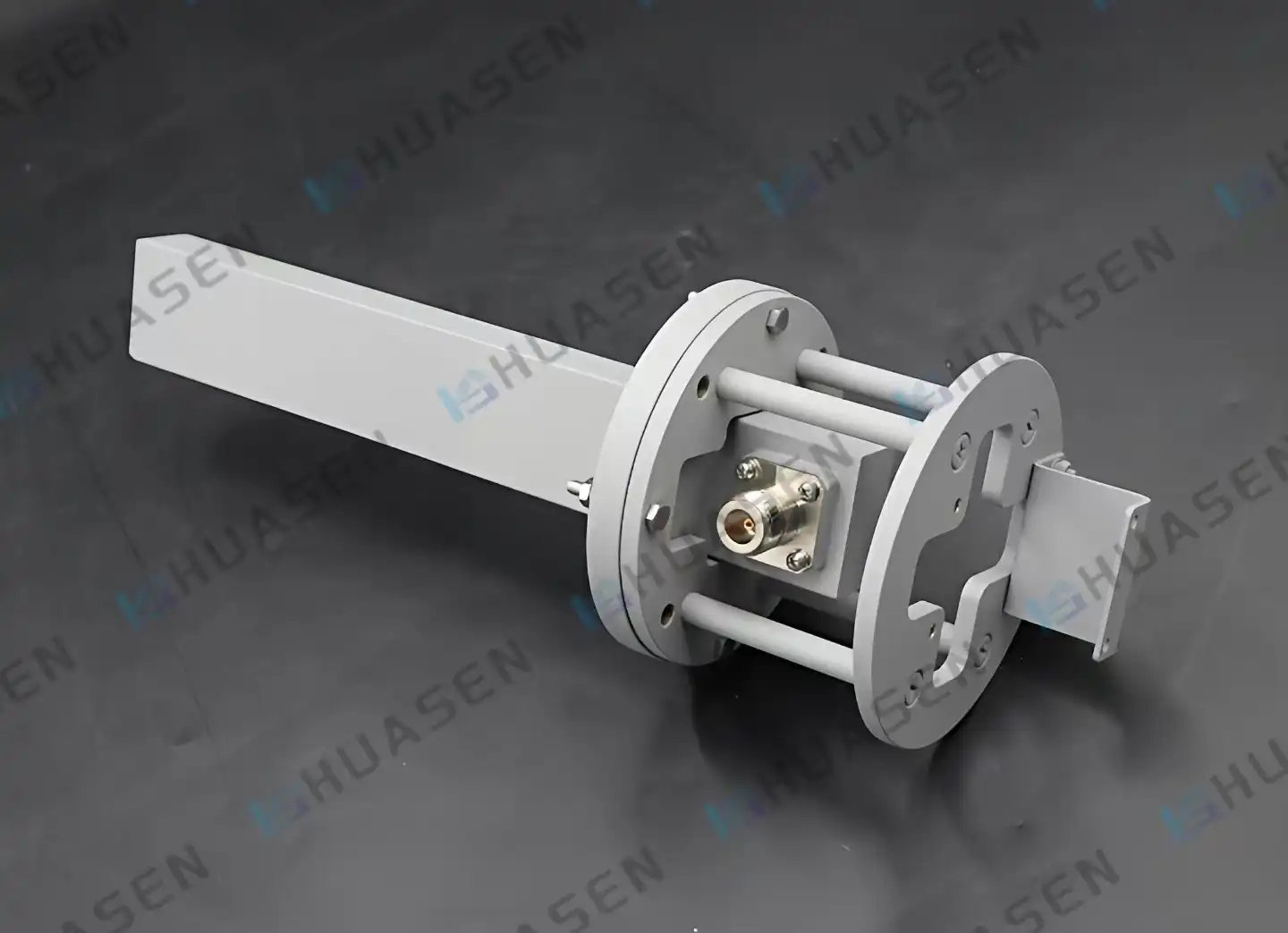
How to suppress reflection in near field measurement probe?
Suppressing reflection in near field measurement probes requires implementing impedance matching techniques, utilizing high-quality absorbing materials, and optimizing probe geometry to minimize signal bounce-back. The Measurement Probe design must incorporate precision-engineered waveguide structures with superior return loss characteristics, typically achieving VSWR values below 1.2:1 across operational frequencies. Advanced probe architectures feature carefully calculated aperture dimensions and specialized coatings that absorb unwanted reflections while maintaining signal fidelity for accurate near-field data acquisition.VIEW MORE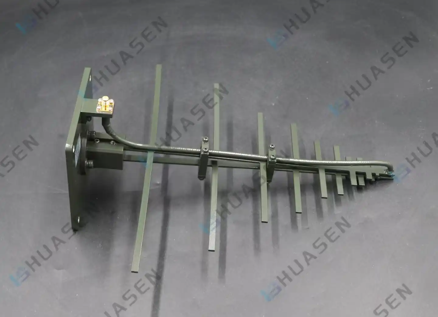
Log Periodic Antenna vs LPDA Antenna: Are They the Same?
Log Periodic Antenna and LPDA (Log Periodic Dipole Array) are essentially the same antenna technology, representing different terminologies for identical electromagnetic structures. The confusion arises from industry naming conventions where "log periodic antenna" serves as the broader categorical term, while "LPDA" specifically describes the most common implementation using dipole elements arranged in logarithmic progression. Both designs employ identical scaling factors, frequency-independent characteristics, and broadband performance principles, making them functionally equivalent for procurement and engineering applications across telecommunications, radar, and defense sectors.VIEW MORE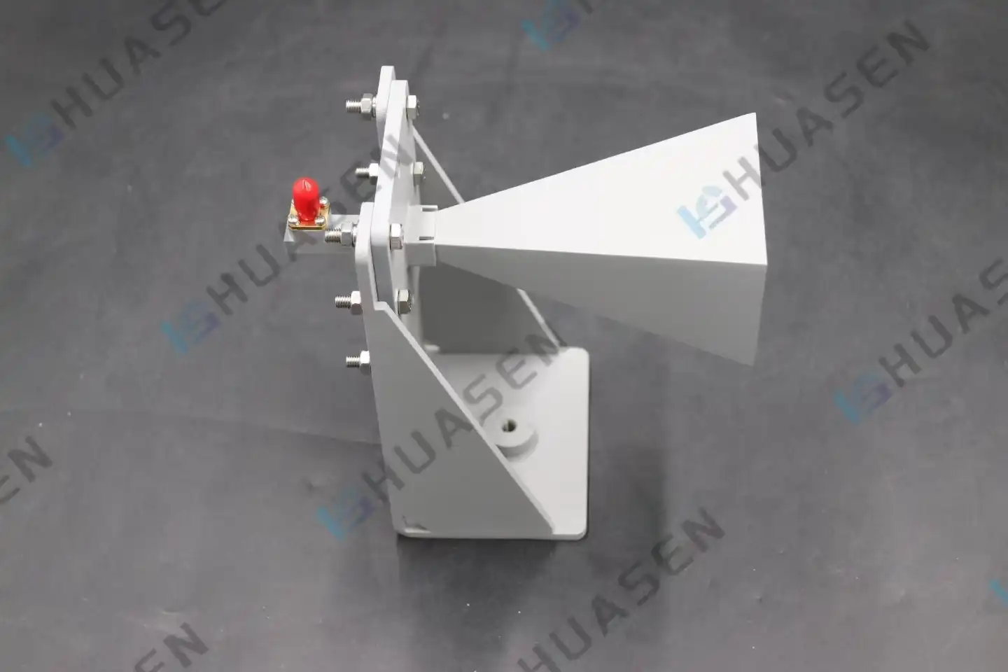
Standard Gain Horn Antenna for Outdoor Test: Dustproof Protection Tips
Standard gain horn antenna technology represents a cornerstone of precision RF measurements, particularly when deployed in challenging outdoor environments. These precision-engineered devices serve as metrological references across frequency ranges spanning 30 MHz to 300 GHz, delivering exceptional accuracy guarantees of ±0.5 dB. However, standard gain horn antenna outdoor testing scenarios expose these valuable instruments to harsh environmental conditions, making dustproof protection strategies essential for maintaining measurement integrity and equipment longevity.VIEW MORE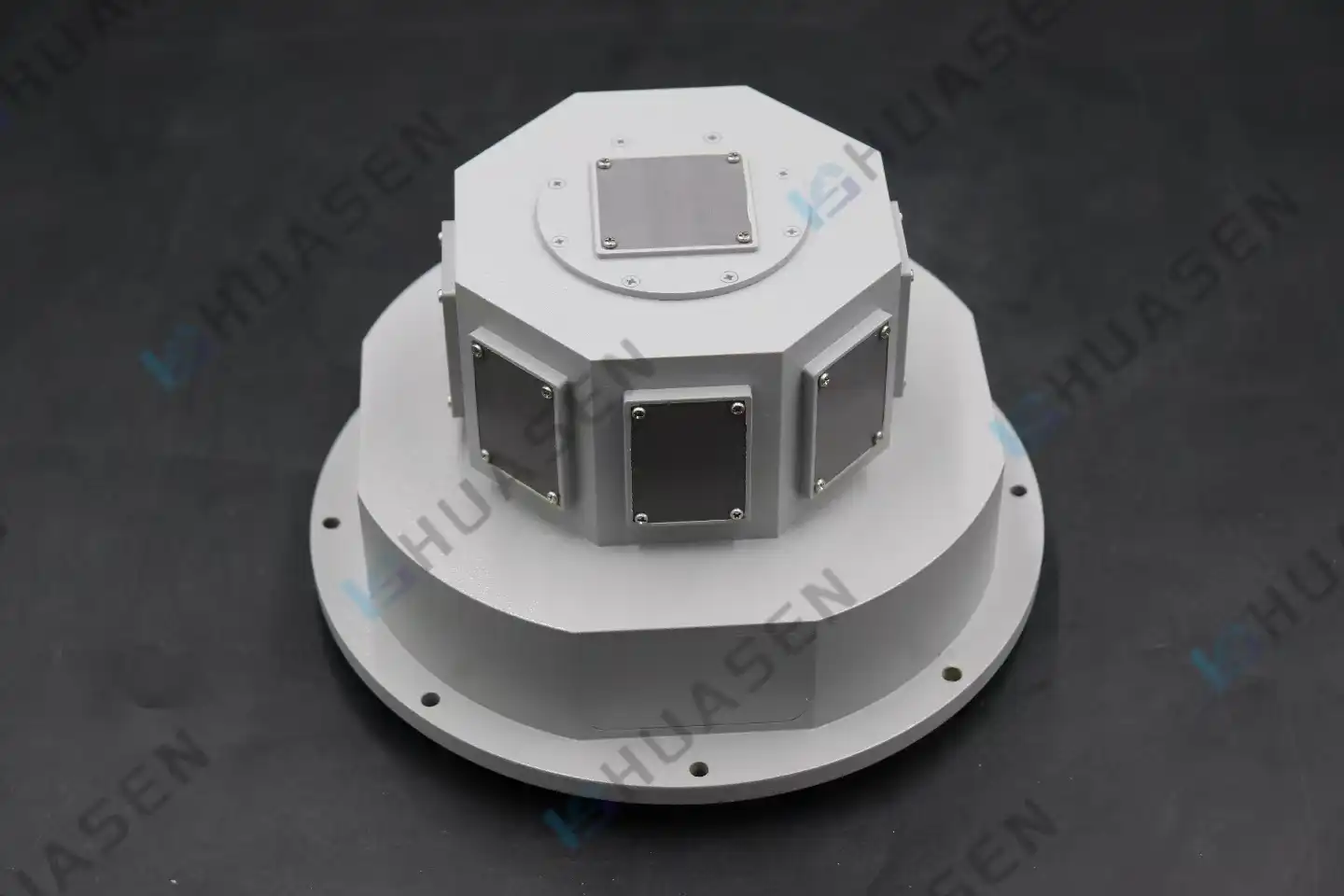
How does dielectric constant influence microstrip antenna characteristics?
The dielectric constant controls how electromagnetic waves move through Microstrip Antenna substrates. It has a direct effect on the resonant frequency, bandwidth, radiation patterns, and total efficiency. When electromagnetic energy moves through various dielectric materials, the wave speed slows down by a factor equal to the square root of the dielectric constant. This causes changes in frequency and resistance. Because of this relationship, engineers can exactly control antenna properties by choosing the right substrate materials. This makes choosing the right dielectric constant an important design parameter for improving performance in radar, telecommunications, Microstrip Antenna, and satellite communication systems.VIEW MORE
- 1
- 40
- 41
- 42
- 43
- 44
- 60
