Why Planar Slot Antenna Is Used in High-Density RF Circuits






2026-07-24 16:24:34
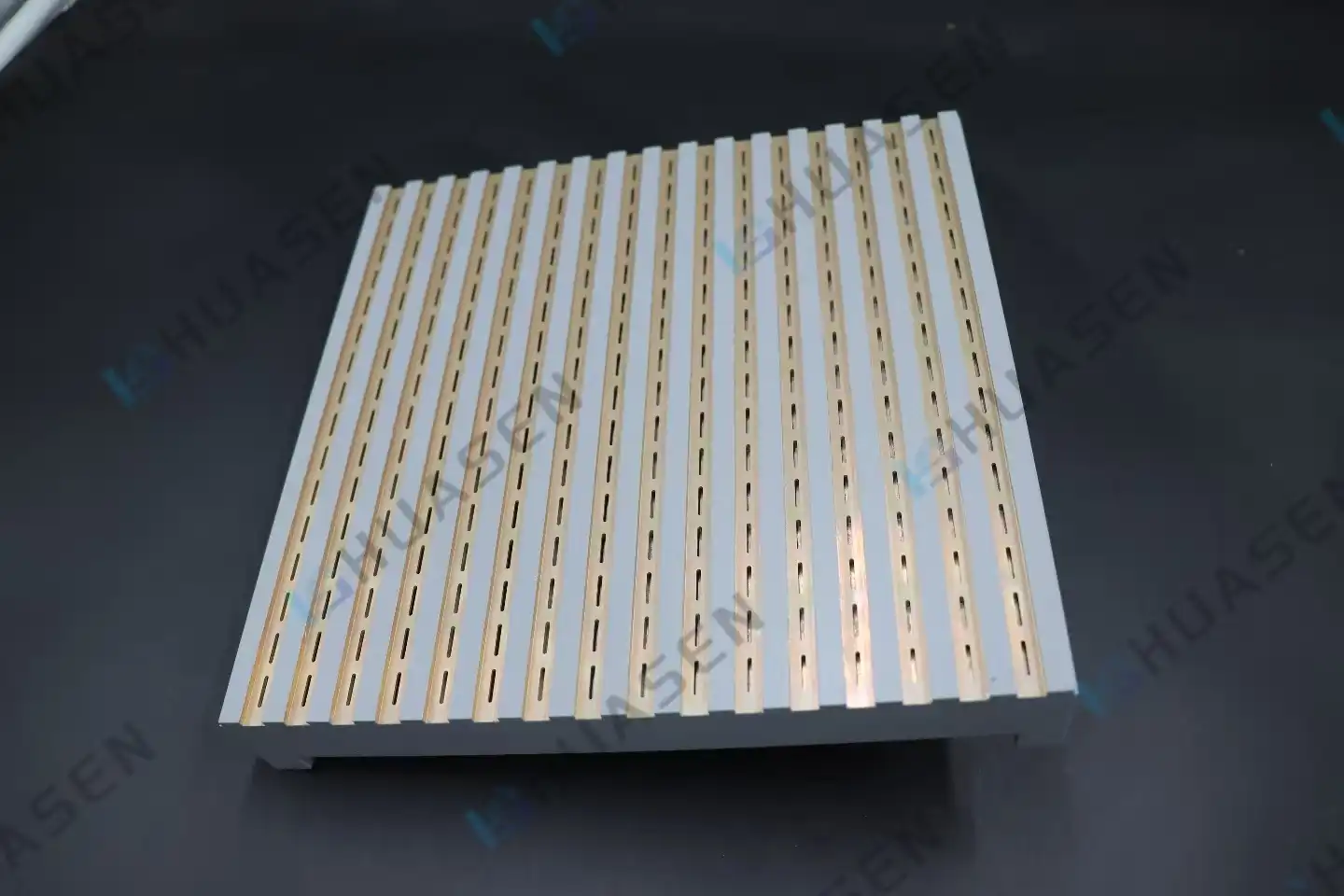
High-density RF circuit design demands antennas that deliver exceptional performance within severely constrained spaces. The planar slot antenna addresses this challenge by leveraging waveguide slot array architecture, where precisely machined resonant slots in a conducting surface create efficient electromagnetic radiation. This configuration eliminates the dielectric losses and thermal management issues inherent in traditional patch designs, making slot arrays ideal for base station front-ends, satellite terminals, and radar systems where every millimeter counts and signal integrity cannot be compromised.
Understanding Planar Slot Antennas and Their Role in High-Density RF Circuits
The Fundamental Operating Principle
Babinet's principle says that a small hole in a conductive surface sends out electromagnetic energy as a magnetic dipole. This is how slot antennas work. By making a bunch of slots in the wide side of a rectangular waveguide, we can connect each slot to the electromagnetic field inside and send it outward. Radiation properties like beam direction, side lobe levels, and polarization purity are determined by how far apart, long, and off-center these slots are.
This method is very different from microstrip patch systems, which have problems with surface wave losses and can't handle a lot of power. Air or low-loss dielectrics are used as the propagation medium in waveguide slot arrays, which can achieve typical efficiencies of more than 85–90% even at millimeter-wave frequencies.
Performance Characteristics in Compact Environments
Antennas for modern high-density RF systems need to be able to work across multiple frequency bands without taking up more space. Slot array designs offer bandwidths between 5 and 8 percent, spanning the 1 to 40 GHz range that is necessary for 5G backhaul lines, satellite uplinks, and airborne radar uses. The vertical beamwidth can be tightly controlled between 3.2° and 4.5°, which lets directional communication links shape the beam precisely.
The horizontal radiation pattern covers all directions at once, so there are no blind spots in drone communication points or marine navigation systems. Base station makers who need constant coverage in busy urban areas where signal reflection and multipath interference make transmission difficult will benefit the most from this omnidirectional feature.
Integration Advantages Over Legacy Antenna Technologies
System designers look at different antenna choices for high-density RF circuits and compare how well they work electrically with how big they are. When it comes to aerodynamic uses on planes and spaceships, waveguide slot arrays are very important because they keep the structure rigid and allow for flush fitting. The metal waveguide structure also works well as a fan, getting rid of the heat that high-power amplifiers in active phased array systems produce.
The flexible slot array layout lets you make your own beamforming without using external phase shifters or power dividers, which makes the RF front-end architecture simpler. Because of this, equipment makers can change the radiation patterns to fit different use cases, like a cosecant-squared pattern for radar used for air traffic control or a narrow pencil beam for point-to-point microwave links.
Comparing Planar Slot Antennas with Other Antenna Types for RF Applications
Structural and Performance Differences
When making small communication systems, RF engineers often look at slot arrays next to microstrip patches, dipoles, and dielectric resonator antennas. Each technology has different trade-offs when it comes to size, efficiency, power handling, and how hard it is to make.
| Antenna Type | Typical Efficiency | Power Handling | Profile Height | Bandwidth | Primary Application |
|---|---|---|---|---|---|
| Waveguide Slot Array | 85–90% | kW to MW range | Capable of flush-mount | 5–8% (standard) | Radar and base stations |
| Microstrip Patch | 60–75% | ~100W | 0.05λ–0.1λ | 3 to 5 percent | WiFi and IoT gadgets |
| Dipole | 75–85% | ~500W | 0.25λ–0.5λ | 10–15% | Broadcasting, cell phones |
| Dielectric Resonator | 80–90% | ~50W | 0.15λ–0.3λ | 8–12% | 5G, mmWave, and satellite |
Microstrip patches and planar slot antennas are easy to use and don't cost much, so they're good for consumer IoT devices that don't need to be very efficient or good at handling power. But when the frequency goes above 28 GHz, dielectric losses in the substrate material make it much less efficient. This means that patches can't be used in 5G mmWave base stations that constantly send data at high power levels.
Dipole antennas have a wider bandwidth, but they need a lot of vertical space, which makes them impossible to mount conformally on car bodies or building facades. Dielectric resonator antennas work well, but they can't handle as much power as radar emitters and military electronic defense systems need.
Application Scenarios in Modern Communication Systems
When setting up 5G infrastructure, network providers have to figure out how to increase reach while keeping the look of the infrastructure the same in cities. Slot array technology solves this problem by letting antennas be built into buildings, streetlight poles, and utility boxes without having parts stick out that could be vandalized or look bad.
For business ships' satellite communication systems to work, the antennas need to be able to handle high humidity and salt spray while still keeping a low VSWR despite mechanical vibrations from the engine rooms and wave action. Waveguide slot arrays meet these needs by using materials that don't rust and strong construction that keeps the shape of the slots even when they're under a lot of stress.
Antennas used in aerospace must work consistently in temperatures ranging from -55°C to +70°C and be able to handle rapid changes in pressure during climb and descent. Because slot arrays are made of metal all the way through, they don't have the thermal expansion problems that come with laminated microstrip structures. This means that the resonance frequency and radiation patterns stay stable throughout the flight range.
Design and Simulation: Ensuring Optimal Planar Slot Antenna Performance
Core Design Parameters and Their Influence
Three important factors affect how well a slot array works electrically: the shape of the slots, the distance between the slots in the array, and how the feed network is set up. The slot length is usually between 0.45λ and 0.5λ at the center frequency, and the width is changed to get the resonant bandwidth that you want. The coupling strength is based on how far away the offset is from the waveguide axis. Larger offsets result in stronger excitation and more power being sent out from each slot.
Array lattice spacing changes how nearby slots talk to each other and how the grating lobe behaves. Spacing less than 0.7λ stops grating lobes from forming but makes mutual coupling stronger, so it's important to match the impedances carefully. When the spacing is bigger than λ, grating lobes form that send energy in the wrong way and make defense systems more likely to get jammed.
For side-lobe control, the design of the feed network combines the need for amplitude drop with the loss of insertion. Binary power division corporate feed networks keep phase coherence across large arrays, but they add cumulative insertion loss. Series feed designs reduce loss as much as possible, but they have beam squint that changes with frequency, which reduces the operational bandwidth.
Simulation Tools and Validation Methods
Full-wave electromagnetic modeling software is used by professional antenna makers to guess how well an antenna will work before they spend a lot of money on a prototype. Maxwell's equations can be solved numerically across the whole antenna structure with tools like ANSYS HFSS, CST Studio Suite, and FEKO. These tools take into account things like surface roughness, finite conductivity, and dielectric losses that closed-form equations can't fully capture.
Simulation workflows start with CAD models that have been parameterized. In these models, variables are used to define the slot sizes, array spacing, and waveguide cross-sections. Automated parametric sweeps find the best shapes that meet the needs for matched impedance, gain, bandwidth, and side lobe level all at the same time. Adaptive meshing methods put most of their computing power in places where the field changes quickly, like slot edges and feed transitions.
Far-field radiation patterns of the planar slot antenna are recorded in anechoic rooms, and the observed gain, beamwidth, and side-lobe levels are compared to what the simulations said would happen. Vector network analyzers measure return loss and insertion loss over the operational bandwidth to make sure that the impedance matching is correct. Environmental stress screening checks the mechanical stability of production units by changing the temperature and causing random vibrations.
Real-World Implementation Success
A major base station maker used waveguide slot arrays in their 26 GHz 5G radio units and got an 88% efficiency rating with side-lobe levels below -25 dB over a 2 GHz bandwidth. The small size of the arrays made it possible for them to be built into radio units that were only 320mm × 180mm × 85mm, which was the right size for installing on rooftops in crowded cities.
Maritime radar manufacturers switched from reflector antennas to slotted waveguide arrays, which cut the weight of the antennas by 40% while keeping the 34dBi gain and making the side lobe performance 3dB better. The built-in waveguide structure got rid of the radome distortion problems that reflector systems had in high winds, making it easier to find targets when the weather is bad.
Table: Huasen Microwave Planar Slot Antenna Key Specifications
| Parameter | Specification | Application Benefit |
|---|---|---|
| Frequency Coverage | 1–40GHz | Supports a range of bands, from L-band to Ka-band |
| Bandwidth | 5 to 8% | Strong enough for narrowband sensors and data links |
| Horizontal Pattern | 360° all-around way | Takes away weak spots in coverage |
| Vertical Beamwidth | 3.2–4.5° (can be changed) | Allows fine control of the slope angle |
| Polarization | Vertical | Designed to work best for base stations and maritime use |
| Array Configuration | Flexible layout of slots | Allows for custom beamforming in certain situations |
These performance traits solve important problems for system designers who need antennas that are the right size, work well, and can handle harsh environments. Modern equipment can only handle a certain amount of space, but the small waveguide slot array structure has the power handling capacity and signal-to-noise ratio needed for reliable long-range communication.
Procurement Considerations for Planar Slot Antennas in B2B Markets
Evaluating Supplier Capabilities and Lead Times
When buying slot arrays for production programs, procurement managers have to look at how well suppliers can make the products beyond what is written in the specifications. Custom slot array development usually takes 8–12 weeks from the time the design is approved until the first product is delivered. Subsequent production runs take an average of 4–6 weeks, but this depends on the size and complexity of the order.
Different providers have very different minimum order amounts. Large contract makers usually have minimum order quantities (MOQs) of 100 units or more. This means that they can be used for high-volume base station operations but not for specialized radar systems that only need 50 units a year. Manufacturers of specialized RF components offer lower MOQs, starting at 10 to 25 units, which makes them easier to use for prototype development and low-rate beginning production.
Detailed datasheets should show performance tests taken at a range of temperatures and under different levels of mechanical stress, not just in a lab setting. Radiation pattern plots need to show both main lines across the whole working bandwidth, with side lobe data going down to -40dB or more below the main beam. Return loss plots should show the margin compared to the requirements, usually aiming for less than -14dB when the requirement is -10dB.
Custom Manufacturing for Specialized Requirements
A lot of high-density RF applications need antenna features that aren't available in standard catalogue items. Custom slot array development meets needs like dual-polarization for MIMO systems, built-in filtering to stop out-of-band interference, and contoured shapes that fit bent mounting surfaces on airplane fuselages.
Setting electrical needs like frequency range, gain, beamwidth, polarization, and power handling is the first step in customizing. The following are mechanical constraints: the largest dimensions, the mounting interface requirements, the type of connector, and the environmental protection class. Material choices and manufacturing process choices are based on cost goals and output volume estimates.
Customers try antennas in typical system setups as part of prototype review. During these trials, they measure integration effects like platform scattering and feed network losses. Customers can characterize whole RF chains with calibration data support, finding system-level problems before committing to production tools.
Reliable Global Suppliers and Huasen Microwave's Capabilities
Companies like Laird Connectivity, Taoglas, Amphenol Antenna Solutions, Molex, TE Connectivity, HUBER+SUHNER, and Rosenberger have been in the global RF component market for a long time. Each has its own set of products aimed at different types of customers, ranging from consumer IoT to aerospace defense applications.
Huasen Microwave Technology Co., Ltd. has been in the slot array market since 1993 and has more than 30 years of experience making waveguide components for telecommunications infrastructure, radar system makers, and military prime contractors. Our engineering team helps customers from the first stages of coming up with an idea to mass production. They do this by helping with design, making sure simulations are accurate, and giving full test data packages.
We make planar slot antennas and waveguide slot arrays that work with frequencies from 1 GHz to 40 GHz and can be customized in terms of bandwidth, beamwidth, and polarization. Our quality control system meets ISO 9001 standards, and the goods we make for the defense program meet MIL-STD-810 environmental standards. We keep agile manufacturing cells that can deliver first articles within six weeks of design approval for customers who need rapid prototyping.
Conclusion
Slot array technology gives modern RF systems the performance density they need by combining high efficiency, strong power handling, and small form factors into a single architecture. The waveguide-based method gets rid of the dielectric losses that make patch antennas less effective at high frequencies. It also makes mechanical integration easier for users with limited space. As communication networks move toward higher frequencies and denser infrastructure, slot arrays have been shown to be a good way to go because they combine electrical performance with ease of making. When buying antennas for next-generation RF systems, procurement teams should look at slot array technology, as well as the supplier's design help and manufacturing maturity, to make sure the program is a success.
FAQ
1. What frequency ranges do waveguide slot arrays support?
Slot arrays can work in all radio frequency and microwave bands, from about 1 GHz to 110 GHz. Lower frequencies below 2 GHz need bigger waveguide cross-sections, which could make them less useful in very small systems. On the other hand, frequencies above 40 GHz are more sensitive to manufacturing errors. For most business uses, the best frequency range is between 3 GHz and 40 GHz. This is because waveguide sizes are still doable, and normal CNC machining can meet manufacturing tolerances.
2. How do slot arrays compare with microstrip patches for 5G applications?
When used in 5G mmWave bands at frequencies above 24 GHz, slot arrays usually have 10–15 percentage points better efficiency than microstrip patches because they have less dielectric loss. Patches are easier to make and cost less for medium-volume uses, but they aren't as good as slot arrays at managing power or heat in base station applications that are constantly sending data. The decision will depend on whether the extra work needed to make the product is worth the benefit in terms of speed and power handling.
3. What are typical lead times and minimum order quantities for custom designs?
From the first review of the design to the release of the first item, custom slot array development takes 8–12 weeks. This time includes electromagnetic modeling, prototype fabrication, and testing in an anechoic room. For orders of 10 to 100 units, the average lead time is 4 to 6 weeks. For repeat orders, shorter lead times are possible once the tools are set up. Minimum order quantities depend on how complicated the supplier's products are. They can be as low as 10 units for custom designs and as high as 100 units or more for high-volume commercial products.
Partner With Huasen Microwave for Your Slot Array Requirements
Choosing the right planar slot antenna maker is important if you want your RF system to meet performance goals on time and on budget. Huasen Microwave blends thirty years of experience in waveguide engineering with flexible manufacturing skills to help customers from the creation of prototypes to mass production. Our engineering team can help you with design, validate your electromagnetic simulations, and give you full test data packages that speed up the approval process.
RF engineering teams and procurement managers are welcome to email us at sales@huasenmicrowave.com for expert advice that is geared to your unique application needs. We have the waveguide slot array solutions your program needs, whether you need standard catalogue products that cover 1–40 GHz or custom array configurations with beamforming that is unique to your needs. You can ask for detailed datasheets, prices based on your volume needs, and time estimates that work with your development plan. Our helpful customer service will make sure you have all the information you need to make an informed choice about where to source your products.
References
1. Balanis, Constantine A. Antenna Theory: Analysis and Design, 4th Edition. Wiley, 2016.
2. Elliott, Robert S. Antenna Theory and Design, Revised Edition. IEEE Press, 2003.
3. Mailloux, Robert J. Phased Array Antenna Handbook, 3rd Edition. Artech House, 2017.
4. Pozar, David M. Microwave Engineering, 4th Edition. Wiley, 2011.
5. Volakis, John L., Editor. Antenna Engineering Handbook, 4th Edition. McGraw-Hill, 2007.
6. Zhang, Y. P., et al. "Substrate Integrated Waveguide Slot Antenna Arrays for Millimeter-Wave Applications." IEEE Transactions on Antennas and Propagation, Vol. 67, No. 4, 2019, pp. 2456-2467.
Send Inquiry