What Is Log Periodic Antenna and Why Use It in Wideband Applications?






2026-07-21 16:53:21
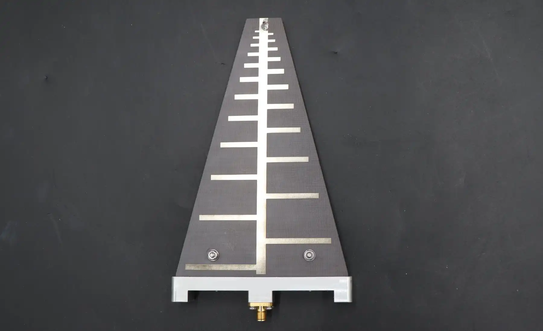
A log-periodic antenna, also called a log-periodic dipole array (LPDA), is a directional antenna that works the same way across very wide bandwidths, often multiple octaves. Its performance is frequency-independent. Its special structure is made up of dipole elements that are spaced and lengthened in a way that is based on logarithms. This lets the "active region" move along the antenna structure as the frequencies change. This design principle gets rid of the problems that come with narrowband antennas. This makes the LPDA the best choice for uses that need reliable coverage from high frequency (HF) to ultrahigh frequency (UHF) bands without sacrificing gain, impedance matching, or radiation characteristics.
Understanding the Log Periodic Antenna
Core Working Principles and Structural Design
The log-periodic antenna design is very smart because it uses self-scaling geometric parameters, which are usually written as Tau (τ) and Sigma (π). These numbers show how each element's length and space compare to those of the elements that came before it. When a signal comes into the antenna's feed system, it automatically excites different parts of the array at different frequencies. Higher frequencies move parts closer to the front of the boom, and lower frequencies move parts farther back. This selective activation mechanism keeps the impedance stable and the directional patterns the same across bandwidths that would need more than one regular antenna to cover.
A lot of the time, the boom itself does two things at once: it supports the structure and is part of the communication line system. The boom is used as an endless balun in high-quality designs to stop common-mode currents that could change the radiation patterns. 6061-T6 aluminum is often used as a material because it is strong, conducts electricity well, and doesn't rust. To meet MIL-STD-810 environmental requirements, manufacturers that want to sell to the defense and aerospace industries often ask for extra passivation treatments or construction out of stainless steel.
Technical Performance Characteristics
When antenna engineers and acquisition specialists look at wideband options, they need to know a few key performance indicators that set good LPDAs apart from average ones. The Voltage Standing Wave Ratio (VSWR) is one of the best ways to tell how well a design was made—a premium LPD. As long as they keep the VSWR below 1.5:1 across their whole operational bandwidth, they can transfer power as efficiently as possible. The gain stability is usually between 6 and 8 dBi, and there isn't much change across the frequency range. In well-designed systems, the front-to-back ratio is over 20 dB.
| Performance Parameter | Typical Value | Critical Application Impact |
|---|---|---|
| Frequency Bandwidth Ratio | 10:1 to 20:1 | Simplifies system design; reduces antenna inventory |
| VSWR | <1.5:1 (premium); <2.0:1 (standard) | Determines transmission efficiency and signal quality |
| Gain Range | 6-8 dBi | Balances coverage with directivity |
| Front-to-Back Ratio | >20 dB | Reduces interference from rear sources |
| Input Impedance | 50 Ohms (standard) | Ensures compatibility with RF systems |
| Polarization | Linear (Horizontal or Vertical) | Must match system requirements |
Due to the fact that the Antenna Factor (AF) is linear across frequency bands, LPDAs are required for accurate readings in EMC testing settings. Compliance facilities that test for radiated immunity or leaks according to IEC 61000-4-3 depend on antenna factors that have been carefully described in order to connect field strength readings with legal limits. Any non-linearity in the AF curve makes measurements less accurate, which can lead to expensive test failures or, even worse, goods that don't meet standards getting on the market.
Frequency Agility and Phase Center Behavior
In fixed-frequency antennas, the radiation comes from a single point. The log periodic array, on the other hand, has a moving phase center that moves along the boom as the operating frequency changes. Elements close to the front send out high frequencies, and elements farther back pick up low frequencies. This effect needs to be taken into account when accurate angle precision is needed for near-field readings and direction-finding tasks.
To keep measurements accurate during automated sweeps, testing labs often write down where the effective phase center is at certain frequencies. Because this shift can be predicted, advanced monitoring systems can use real-time correction factors to keep direction-finding algorithms accurate even when they are following signals that change frequency.
Advantages of Log Periodic Antennas in Wideband Applications
Superior Frequency Coverage and Operational Flexibility
System integrators and equipment makers are always under pressure to cut down on the number of parts they use while also making their products more useful. Traditional methods that need different antennas for each frequency band make it harder to put the system together, make it heavier, add more places where it could fail, and make upkeep more difficult. Because log-periodic antennas are broadband, they directly address these problems by combining several narrowband antennas into a single package.
Think about a typical 5G base station front-end that needs to cover bands below 6 GHz. Using traditional methods, you might need three or four separate antenna systems, each with its own feed networks, combiners, and switching mechanisms. If you specify the LPDA correctly, it can provide continuous coverage from 600 MHz to 6 GHz with stable radiation characteristics. This makes the RF architecture a lot easier to understand. In high-power transmission situations, the choice of antenna is often justified by the lower amount of passive intermodulation (PIM) products that come from getting rid of combiners.
Performance Comparison with Alternative Antenna Technologies
Different antenna architectures are used for different things, and engineers can make better decisions when they know how strong each one is compared to the others. Yagi-Uda antennas have higher gain (12–18 dBi), but they lose bandwidth and usually only work well across 10–20% of the bandwidth. On the other hand, discone antennas cover all directions over wide frequency ranges, but they have negative gain and don't have directional control, which is needed to reduce interference.
The following comparison illustrates key differences across common wideband antenna types:
| Antenna Type | Bandwidth | Typical Gain | Directivity | Primary Applications |
|---|---|---|---|---|
| Log Periodic Array | Very Wide (10:1+) | 6-8 dBi | Directional | EMC testing, spectrum monitoring, tactical comms |
| Yagi-Uda | Narrow (<20%) | 12-18 dBi | Highly Directional | Point-to-point links, broadcast reception |
| Discone | Very Wide | -2 to 0 dBi | Omnidirectional | Scanning receivers, wideband monitoring |
| Biconical | Wide (3:1 to 5:1) | 0-2 dBi | Omnidirectional | EMC emissions testing |
| Spiral | Ultra-Wide | 3-6 dBi | Directional (circular polarization) | Satellite communications, direction finding |
Log-periodic arrays are one of a kind because they balance bandwidth, gain, and directivity. They don't have the high gain of narrowband designs, but they have much better direction control than omnidirectional broadband options. Because of this balance, they work great in situations where signal direction is important and frequency flexibility can't be lost.
Real-World Application Benefits Across Industries
Precision log-periodic antennas are bought by EMC testing sites, which is one of the biggest business markets for them. For full compliance testing, anechoic chambers must be able to sweep frequencies from 80 MHz to 6 GHz or higher. Manual antenna changes can't be made during automated test routines that run overnight without being watched. When an LPDA is calibrated, it can do continuous frequency sweeps. This cuts the test time from days to hours and gets rid of the measurement errors that come from connector cycling and cable movement.
Defense and spectrum tracking groups put movable LPA LPDAs on high buildings to gather information about signals and enforce the law. When keeping an eye on complicated radio frequency environments where transmitters may change frequencies to avoid being picked up or causing interference, the instantaneous bandwidth of a log-periodic array ensures that no signals get lost because of antenna limitations. The directional properties make triangulation and positioning possible with a level of accuracy that is not possible with wide-receiving devices.
More and more, maritime and aircraft communications systems use LPD. As for long-distance data lines, their frequency diversity makes them resistant to both atmospheric fade and deliberate jamming. With an LPDA, a tactical radio operator can quickly switch between HF and VHF bands without the need for antenna tuners or field-expedient wire configurations. This lets them keep talking even when signal conditions are bad.
Selecting the Right Log Periodic Antenna for Your Business Needs
Critical Specification Parameters for Procurement
Getting the right antenna starts with having clear technical requirements that come from system-level specifications. The main thing that is used to choose an antenna is its frequency range. It needs to be able to cover all operational bands plus some extra ones for safety and regulatory compliance. How much gain is needed depends on how much path loss, receiver sensitivity, and emitter power are taken into account in the link budget estimates. When defining a radiation pattern, it's important to think about whether sidelobe suppression is needed to reduce interference or whether a wider beamwidth is better for coverage applications.
When installing something outside, the weather conditions often make all the difference. When antennas are put on poles, building roofs, or mobile platforms, they have to be able to handle wind loads, ice buildup, high temperatures, and conditions that are bad for electronics. Standards like MIL-STD-810 for shock and vibration, ASTM B117 for salt-fog corrosion resistance, and wind survival ratings that are right for the area should be used in the specifications. The specs of the connectors need to fit the infrastructure that is already in place. For example, N-type connectors work best for most uses below 6 GHz, while 7/16 DIN connections can handle higher power levels and have better PIM performance.
Evaluating Manufacturers and Supply Chain Reliability
On the global market, there are many companies that make antennas, from low-cost commodity makers to high-tech engineering firms that work with the defense and aerospace industries. In addition to unit price, procurement decisions should take into account the accuracy of the calibration, the quality of the documentation, the ability to customize, and the support provided after the sale. Manufacturers who offer individual calibration certificates that can be tracked back to national standards (NIST, PTB, and NPL) charge more, but they remove doubt in measurement uses that are very important.
Since 1993, Huasen Microwave Technology Co., Ltd. has been in the business of high-frequency RF components. With 30 years of engineering experience, they can design and make LPA (log-periodic antennas). Our range of log-periodic antennas covers bands from 30 MHz to 6 GHz, and their performance has been shown to meet international EMC testing standards. Each antenna comes with calibration data that can be tracked back to a recognized measurement institution. This helps customers who run accredited test labs or calibration facilities.
Stability in the supply chain is important for OEM customers who put antennas in products that will last for more than one year. Well-known companies stick to the same designs, so when you need to replace an antenna, it will still work with your system without the need for recertification. Technical support, such as integration advice, measurement help, and custom design services, adds value that goes beyond the component itself.
Pricing Dynamics and Procurement Strategies
Antenna prices depend on how complicated, accurate, and well-positioned they are in the market. Basic models with no tuning information and simple builds start at around $200 to $500 for VHF and UHF bands. Precision EMC-grade antennas that are individually calibrated, made of high-quality materials, and have wider frequency coverage cost between $1,500 and $5,000. Custom designs that deal with particular frequency combos, polarization needs, or environmental standards cost more but can't be compromised in serious situations.
Buying in bulk can help you save money and make sure that your supplies get to you first. Manufacturers can make the best use of their production schedules and material purchases with the help of annual purchase agreements and volume discounts, which are passed on to customers. Technical relationships with antenna providers often give engineers access to resources that help improve systems, test samples before they are made, and work together to solve problems when they come up during integration.
Conclusion
Log-periodic antennas deliver unmatched frequency agility and consistent performance for wideband RF applications ranging from EMC compliance testing to tactical communications and spectrum monitoring. Their unique self-scaling architecture maintains stable impedance, gain, and radiation patterns across bandwidths that would otherwise require multiple narrowband antennas, simplifying system design while reducing cost and complexity. Selecting appropriate specifications, evaluating manufacturers on technical capability and supply chain reliability, and implementing proper integration practices ensure these versatile antennas deliver their full performance potential. Whether supporting 5G infrastructure deployment, defense communications systems, or precision test environments, log-periodic technology provides the frequency coverage and reliability modern RF systems demand.
FAQ
1. What distinguishes a log periodic antenna from a Yagi antenna in practical applications?
Yagi antennas optimize gain (typically 12-18 dBi) across narrow bandwidths, usually 10-20% of the center frequency. Log periodic arrays sacrifice peak gain (6-8 dBi) to operate across 10:1 or wider frequency ranges with consistent characteristics. Choose Yagi designs when maximizing range on a fixed channel matters most; select LPDAs when frequency agility and broad coverage outweigh absolute gain requirements.
2. Can log-periodic antennas handle high-power transmission applications?
Standard commercial LPD. As they typically handle 50-100 watts continuous power, they are adequate for most communications and test applications. High-power variants designed for broadcast, jamming, or radar applications incorporate heavy-duty element construction, air-dielectric feed lines, and 7/16 DIN or larger connectors to handle kilowatts safely. Power handling depends critically on feed system design and connector quality—confirm specifications match your power requirements before procurement.
3. Why does the phase center shift in log-periodic antennas, and how does this affect direction finding?
Different frequency components excite different physical regions along the antenna—high frequencies activate front elements while low frequencies engage rear elements. This causes the effective radiation origin (phase center) to move along the boom. Direction-finding systems must apply frequency-dependent position corrections to maintain angular accuracy when tracking signals across wide bandwidths. Precision applications require documented phase center locations at specific frequencies.
4. What mounting considerations prevent pattern distortion with log-periodic antennas?
Mount the antenna clear of metallic structures that might couple parasitically with elements. Feed cables should exit along the boom toward the longest elements rather than perpendicular to the boom. Non-metallic mounting hardware reduces unwanted coupling. Ferrite chokes suppress common-mode currents on the feed line's outer shield that would otherwise compromise front-to-back ratio and pattern symmetry, which are particularly important for EMC testing and direction-finding applications.
Partner with Huasen Microwave for Your Wideband Antenna Solutions
Selecting the optimal log-periodic antenna requires balancing technical specifications with budgetary constraints and delivery timelines. Huasen Microwave Technology brings over 30 years of RF engineering expertise to every customer engagement, offering both standard catalog antennas and fully customized designs addressing unique frequency combinations, environmental requirements, and mechanical constraints. Our engineering team collaborates with system integrators, test laboratories, and equipment manufacturers to specify antennas delivering measurable performance advantages aligned with project objectives.
We invite procurement managers and RF engineers to explore our comprehensive antenna portfolio covering frequencies from HF through millimeter-wave bands. Request detailed technical datasheets, calibration reports, and performance data demonstrating compliance with international standards, including ANSI C63.5 and IEC 61000 series requirements. Our applications engineering team provides complimentary design consultation, helping match antenna specifications to your specific use case, whether that involves 5G infrastructure, aerospace communications, spectrum monitoring, or EMC compliance testing.
Contact our sales team directly at sales@huasenmicrowave.com to discuss your wideband antenna requirements. We offer sample evaluation programs allowing hands-on performance validation before volume commitments. As an established Log Periodic Antenna supplier with proven reliability across defense, telecommunications, and test equipment markets, Huasen Microwave stands ready to support your next-generation RF system development with components meeting the highest standards for quality, performance, and long-term availability.
References
1. Balanis, Constantine A. "Antenna Theory: Analysis and Design, Fourth Edition." John Wiley & Sons, 2016. Chapter 10: Frequency Independent Antennas.
2. Carrel, R. L. "Analysis and Design of the Log-Periodic Dipole Antenna." Technical Report No. 52, Antenna Laboratory, University of Illinois, 1961.
3. Institute of Electrical and Electronics Engineers. "IEEE Standard for Definitions of Terms for Antennas." IEEE Std 145-2013. IEEE Press, 2014.
4. International Electrotechnical Commission. "IEC 61000-4-3: Electromagnetic Compatibility - Testing and Measurement Techniques - Radiated, Radio-Frequency, Electromagnetic Field Immunity Test." Edition 4.0, 2020.
5. Stutzman, Warren L., and Gary A. Thiele. "Antenna Theory and Design, Third Edition." John Wiley & Sons, 2012. Chapter 8: Broadband Antennas.
6. United States Department of Defense. "MIL-STD-810H: Environmental Engineering Considerations and Laboratory Tests." Department of Defense Test Method Standard, 2019.
Send Inquiry