Omnidirectional Antenna Performance in Outdoor Environments






2026-07-21 16:53:15
You can test radio-frequency transceivers' omnidirectional antenna performance in outdoor environments to see how well they work when they are set up outside and are supposed to send and receive electromagnetic waves evenly across 360 degrees in a horizontal plane. These receivers make sure that the information gets to everyone, no matter where they are. For wide-area uses like base stations, naval communications, wireless bridges, and mobile infrastructure, this makes them very important. There are many things outside that can make the gearbox less effective, the VSWR unstable, and the signal-to-noise ratio lower. These include weather exposure, physical obstacles, and changes in the terrain. Designers of antennas need to think about how to keep gain flatness, polarization integrity, and weather robustness so that networks stay stable over time in tough settings.
Understanding Omnidirectional Antennas in Outdoor Settings
Omnidirectional antennas are designed to send out the same amount of radiation in all directions while focusing energy at certain elevation points. This feature is very useful in outdoor wireless systems where user devices, or receivers, are spread out around a central transmitter at random. In contrast to directional antennas, which guide energy toward a specific target, these devices make network design easier because they don't need to be perfectly aligned when they are installed.
Working Principles and Radiation Patterns
Radiation works in different ways depending on the shape of the antenna parts. Phase coherence is made by things like dipoles, collinear groups, or special structures like cone assemblies. It creates patterns that are circular in the horizontal plane. These parts make fields when electromagnetic currents run through them. These fields make the antenna stronger. Most of the time, this omnidirectional antenna trait is true in the azimuth direction. Higher gain models, on the other hand, tend to have narrower beamwidths in the elevation pattern. People who work on systems should know that real 360-degree coverage has costs. One way that higher-gain antennas work is by making the vertical beamwidth smaller. This can leave coverage holes at sharp angles.
Common Frequency Bands and Applications
Outdoor operations use a range of band licenses, based on the needs of the application. Most WiFi bridges and point-to-multipoint backup links use the 2.4 GHz and 5 GHz ISM bands. This is especially true in university networks and commercial IoT settings. Bands from 698 MHz to 6 GHz are used a lot by cellular infrastructure. These bands cover 4G LTE and 5G Sub-6 services. Maritime and satellite communications often use bands above 2 GHz and in the L-band. This requires antennas that can withstand harsh conditions. When military and radar systems use microwave and millimeter waves, ultra-wideband solutions are very important for electronic warfare and countermeasures.
Key Antenna Structures for Outdoor Use
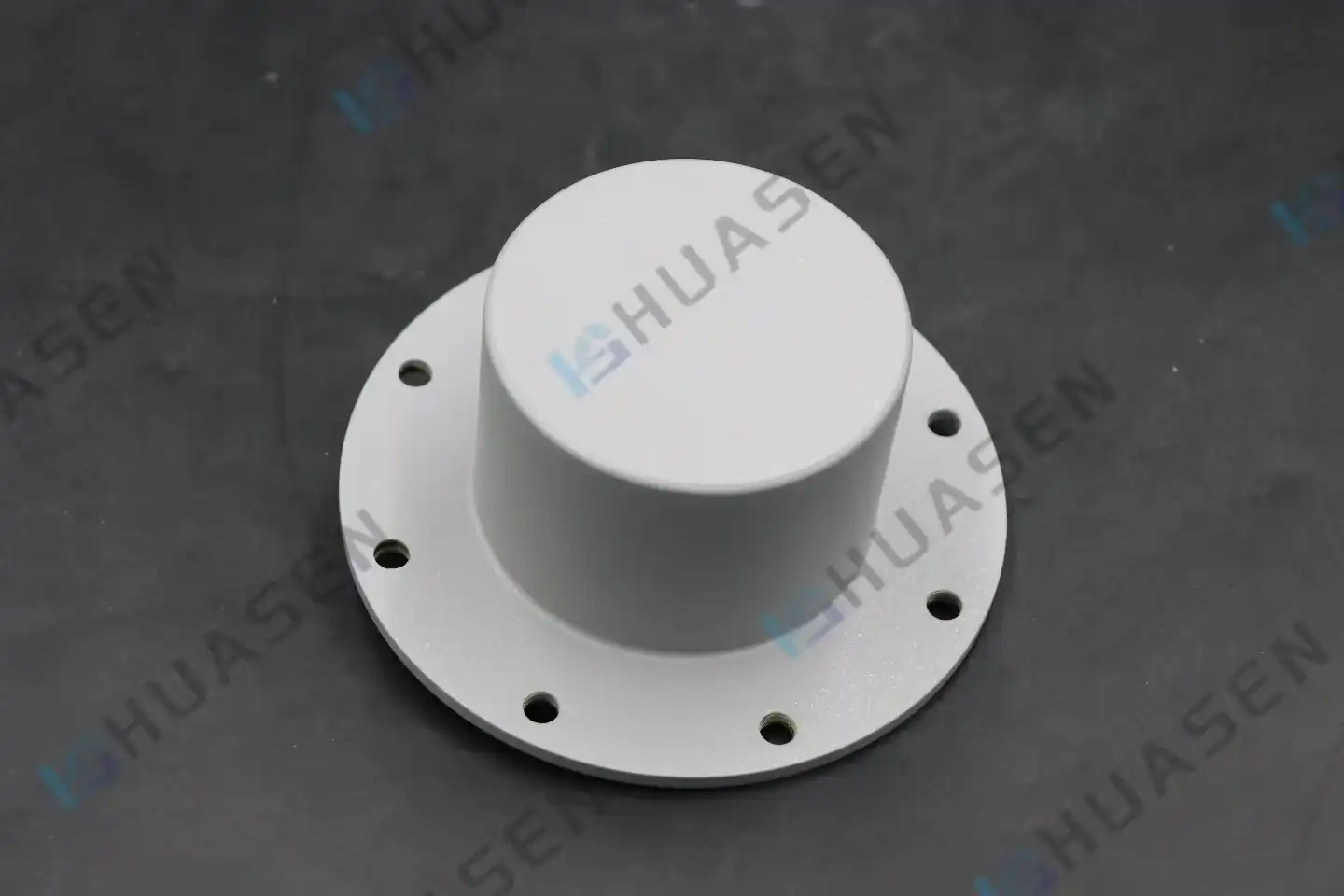
Different physical implementations meet different performance and environmental needs. Dipole antennas are easy to use and have a modest gain, making them good for short-range uses where money is tight. Multiple radiating elements are stacked vertically in a collinear array to get a higher gain (usually 5–9 dBi) by narrowing the elevation beamwidth while keeping the horizontal omnidirectionality. Fiberglass radome-enclosed designs keep the inside parts safe from UV damage, water entry, and toxic atmospheres, which increases their useful life in seaside or industrial areas. The ultra-wideband omnidirectional antenna (CVOA) from Huasen Microwave uses special cone structures, such as the single cone, the umbrella cone, the cage, and the whip configurations, to provide true omnidirectional radiation over very wide frequency ranges while keeping small sizes starting at φ23×399 mm.
Key Factors Affecting Omnidirectional Antenna Performance Outdoors
When propagation problems happen outside, they are different from those that happen inside. The weather, the shape of the land, the amount of vegetation, and man-made structures all play a role in determining whether an antenna system meets its coverage and reliability goals or not.
Environmental Elements and Signal Propagation
It rains, snows, or fogs, and those things soak up waves. This makes the losses worse with frequency, especially above 10 GHz. Link budgets can drop by several decibels when the weather is bad. When temperatures change, high thermal expansion factors in the materials used in an antenna can put stress on its mechanical parts and change the frequencies at which it vibrates. When there is a lot of wind, antennas on masts can shake and bend, which could throw off the polarization or cause connection problems at coaxial interfaces that happen from time to time. When metal surfaces are exposed to salt spray in marine settings, they rust. This lowers conductivity and increases insertion loss over time if protective coats and sealed connection designs are not used.
Signals can bounce off of things like rocks, buildings, or big cars, which is called multipath. When these signals reach receivers, they have changed phases, which causes fade. When leaf sizes get close to wavelengths in the VHF and UHF ranges, leaves act as a lossy dielectric, taking in RF energy and scattering wavefronts in ways that are hard to predict. Signals are bent and reflected by metal junk in urban areas and industrial parks, so full site studies are needed to find coverage gaps and the best places to put omnidirectional antennas.
Installation Best Practices and Mounting Guidelines
To get the best results, placement factors must be carefully considered. Line-of-sight (LOS) chance and coverage radius are directly affected by mounting height. For effective contact, at least 60% of the first Fresnel zone must stay open according to the Fresnel zone clearing principle. In flatland, a 10-meter rise in elevation can improve range by several kilometers. But as you go higher, the benefits decrease because ground echoes cause harmful interference.
Grounding and lightning protection protect both the tools and the people who use them. Using heavy-gauge copper conductors that are bonded to earth stakes with resistance below 10 ohms to make the right grounding paths stops static electricity from building up and lets lightning-caused surges escape. When installed in line with coaxial feedlines, gas discharge tubes or solid-state surge suppressors stop voltage spikes before they get too dangerous. However, these devices add small insertion losses that need to be taken into account in link budgets.
Orientation is less important when building an omnidirectional antenna in azimuth, but it is still very important for making sure the polarization is straight. Ground echoes make vertically polarized waves stronger, so most outdoor communications use them. Horizontal polarization, on the other hand, has trouble with phase cancellation. Cross-polarization interference is less likely to happen if the antenna stays upright. You can check this with bubble levels or inclinometers.
Omnidirectional vs. Directional Technologies
You should pick either a wide or a pointed antenna based on how you want to deal with interference and range. These antennas work best in places where they need to serve a lot of people at once, like radio towers, base station cells, and emergency contact points. Their smooth azimuthal pattern makes it easier to plan networks and lets users move around without making handoffs harder. Directional antennas, such as Yagi, parabolic, and panel types, direct energy to specific places or sites that are far away. This raises the gain and lowers the amount of interference coming from bad directions. Antennas that can send and receive signals in all directions are used at hub sites to serve local areas, while directional links are used for long-distance backhaul connections.
| Parameter | Omnidirectional Antenna | Directional Antenna |
|---|---|---|
| Azimuthal Coverage | 360° horizontal | 30°–120° beamwidth |
| Typical Gain Range | −20 dBi to 12 dBi | 10 dBi to 30+ dBi |
| Installation Complexity | Low (no alignment needed) | High (precise pointing required) |
| Interference Rejection | Limited | Excellent (front-to-back ratio) |
| Ideal Applications | Base stations, IoT gateways | Point-to-point backhaul, radar |
Selecting the Best Omnidirectional Antenna for Outdoor Applications
When making a procurement decision, technical specifications must be carefully looked at while budget limits and deployment schedules are taken into account. The antenna you choose has a direct effect on the network's capacity, reliability, and total cost of ownership over a number of years.
Technical Criteria and Performance Metrics
Gain tells you how well an omnidirectional antenna can focus the power it sends out compared to an isotropic radiator. When the elevation beamwidth is narrowed, the gain value goes up. This makes the coverage radius bigger, but the vertical coverage angles smaller. For uses that need to reach areas that are higher or lower, like hilly regions or buildings with many floors, lower-gain antennas with wider vertical patterns may be needed to avoid dead spots.
VSWR measures how well the antenna and transmission line match in terms of impedance. Values below 2.0:1 across the operating band make sure that less than 11% of the power being sent is reflected back toward the source. This keeps the amplifiers working at their best and prevents damage. The VSWR of high-end antennas stays below 1.5:1 thanks to careful impedance taper designs and quality control during production.
The antenna's frequency compatibility includes both its working range and its ability to keep working well across a number of different bands. Spectrum separation is a problem for the business world. This problem can be solved by ultra-wideband designs that combine 5G, WiFi 6E, and IoT protocols into a single unit. This makes buildings lighter and lowers the cost of setting them up. Huge frequency range and strength values from -20 dB to 6 dB are found in the CVOA line from Huasen Microwave. System integrators can now combine several narrowband antennas into a single, light solution that is a lot lighter than similar arrays of multiple antennas.
The difference between installations that last a long time and ones that break down quickly is how well they hold up in harsh conditions. When UV-stabilized radomes are left out in the sun all the time, they don't break down. This means that they keep their mechanical strength and RF clarity for decades. Hot-dip galvanization or marine-grade anodization are two coatings that don't rust and keep metal and steel parts safe at the beach or in the workplace. If your shelter is covered by IP67 or IP68 grades, make sure that it can handle being flooded and getting dust inside. This is important for antennas that are on open structures, ships, or cars.
Product Specifications Table
| Specification | Huasen CVOA Series |
|---|---|
| Frequency Range | Ultra-wideband (custom ranges available) |
| Gain | −20 dB to 6 dB |
| VSWR | < 2.0:1 (typical < 1.5:1) |
| Polarization | Vertical |
| Radiation Pattern | Omnidirectional (360° azimuth) |
| Connectors | N-type, SMA, K-type standard |
| Dimensions (min) | φ23 × 399 mm |
| Weight | Lightweight, portable design |
| Structure Types | Single cone, umbrella cone, cage, whip |
| Environmental Rating | Weatherproof, corrosion-resistant materials |
Balancing Budget and Performance Expectations
Investment decisions often involve trade-offs between upfront costs and lifecycle expenses. Budget-tier antennas using basic materials and loose manufacturing tolerances may exhibit VSWR drift, premature connector corrosion, and mechanical failures within 2–3 years. These hidden costs—including truck rolls for replacement, network downtime, and customer dissatisfaction—frequently exceed the initial savings. Premium solutions engineered with precision-machined components, gold-plated contacts, and rigorous environmental testing deliver measurable return on investment through extended mean time between failures (MTBF) exceeding 15 years and consistent performance that maintains link budgets without degradation.
Procurement teams should request detailed datasheets for omnidirectional antennas showing measured radiation patterns, VSWR curves across temperature ranges, and third-party test certifications (MIL-STD-810, IEC standards). Suppliers offering calibration data, sample trials, and post-deployment technical support demonstrate commitment to customer success beyond the purchase transaction.
Conclusion
Optimizing outdoor antenna performance requires balancing technical specifications, environmental resilience, and lifecycle economics. Omnidirectional antenna designs deliver unmatched coverage simplicity for applications ranging from cellular base stations to maritime communications, provided procurement teams select solutions engineered for longevity. Huasen Microwave's CVOA series exemplifies the advanced engineering necessary for demanding installations—ultra-wideband coverage, low VSWR, lightweight portability, and robust construction address the complete spectrum of customer pain points, from spectrum fragmentation to harsh-environment operation. As networks evolve toward 5G, IoT integration, and higher frequencies, investing in proven antenna technology from manufacturers with three decades of RF expertise ensures infrastructure reliability that supports business-critical communications for years ahead.
FAQ
1. What transmission range can outdoor omnidirectional antennas achieve reliably?
Range depends on multiple variables: transmit power, frequency band, antenna gain, receiver sensitivity, and terrain. At 2.4 GHz with typical WiFi power (20 dBm) and 5 dBi antennas, the line-of-sight range reaches 300–500 meters in open areas. Cellular base stations at 1800 MHz with 9 dBi antennas and 43 dBm transmit power achieve a 2–5 kilometer cell radius in suburban environments. Obstructions like buildings and foliage reduce these ranges by 50–80%. Link budget calculations using the Friis transmission equation provide accurate predictions for specific deployments.
2. How do omnidirectional antennas differ from directional types in practical use?
Omnidirectional antennas radiate equally in all horizontal directions, ideal for serving multiple users distributed around a central point—WiFi access points and base stations. Directional antennas focus energy toward specific targets, achieving higher gain and longer range but requiring precise alignment. System architects choose omnidirectional designs when coverage area matters more than maximum distance, and directional designs when point-to-point links need interference rejection and extended reach.
3. What protections prevent outdoor antenna damage from weather and lightning?
Weatherproof radomes using UV-stabilized fiberglass or ASA polymers shield internal elements from rain, ice, and solar radiation. Sealed connectors with O-rings achieve IP67/IP68 ingress protection against moisture. Lightning protection employs proper grounding—copper conductors to earth stakes maintaining under 10-ohm resistance—plus inline surge suppressors (gas discharge tubes or polyphase protectors) that clamp transient voltages. Mounting antennas below the highest point on structures and using dedicated lightning rods diverts direct strikes away from sensitive RF equipment.
Partner With Leading Omnidirectional Antenna Manufacturers for Your Next Deployment
Huasen Microwave Technology brings over 30 years of precision RF engineering to outdoor wireless infrastructure challenges. Our ultra-wideband CVOA Omnidirectional Antenna series combines advanced cone structures with rigorous quality control, delivering 360° uniform coverage, exceptional VSWR performance below 1.5:1, and compact form factors starting at just φ23×399mm. Whether you're deploying 5G base stations, maritime communication systems, or multi-band IoT gateways, our vertical polarization designs maintain stable reception across the most demanding frequency ranges.
We support system integrators and equipment manufacturers with customized solutions, comprehensive test data, and responsive engineering assistance throughout your project lifecycle. Contact our technical team at sales@huasenmicrowave.com to discuss bulk procurement options, request sample evaluations, or explore how our proven antenna technology can enhance your network reliability and reduce total cost of ownership.
References
1. Balanis, Constantine A. Antenna Theory: Analysis and Design. 4th ed. Hoboken: John Wiley & Sons, 2016.
2. Rappaport, Theodore S. Wireless Communications: Principles and Practice. 2nd ed. Upper Saddle River: Prentice Hall, 2002.
3. Huang, Yi and Boyle, Kevin. Antennas: From Theory to Practice. Chichester: John Wiley & Sons, 2008.
4. IEEE Standard 145-2013. IEEE Standard for Definitions of Terms for Antennas. New York: Institute of Electrical and Electronics Engineers, 2014.
5. Kraus, John D. and Marhefka, Ronald J. Antennas for All Applications. 3rd ed. New York: McGraw-Hill, 2002.
6. Volakis, John L., editor. Antenna Engineering Handbook. 4th ed. New York: McGraw-Hill Professional, 2007.
Send Inquiry