How standard gain horn antenna Achieves Accurate Calibration






2026-04-30 22:41:30
Standard gain horn antennas can be accurately calibrated because their design is based on physics, and their radiation characteristics are always the same. In contrast to broadband test antennas, these precise instruments have geometrically calculated dimensions that make theoretical gain curves that match measurements. Because they have stable radiation patterns, few sidelobes, and linear polarization, they are essential reference standards for RF measurement labs. They help engineers set up traceability chains and get rid of uncertainty in antenna gain transfer methods, chamber calibrations, and field strength verification procedures.
Understanding Standard Gain Horn Antennas and Their Role in Calibration
What Defines a Precision Calibration Horn?
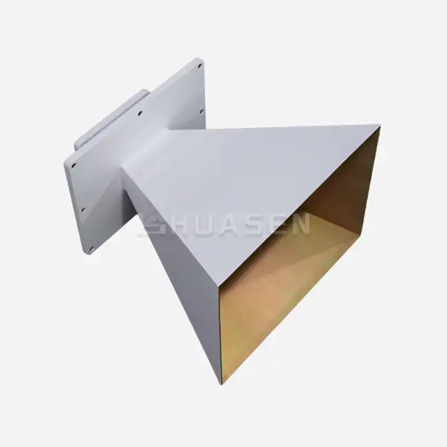
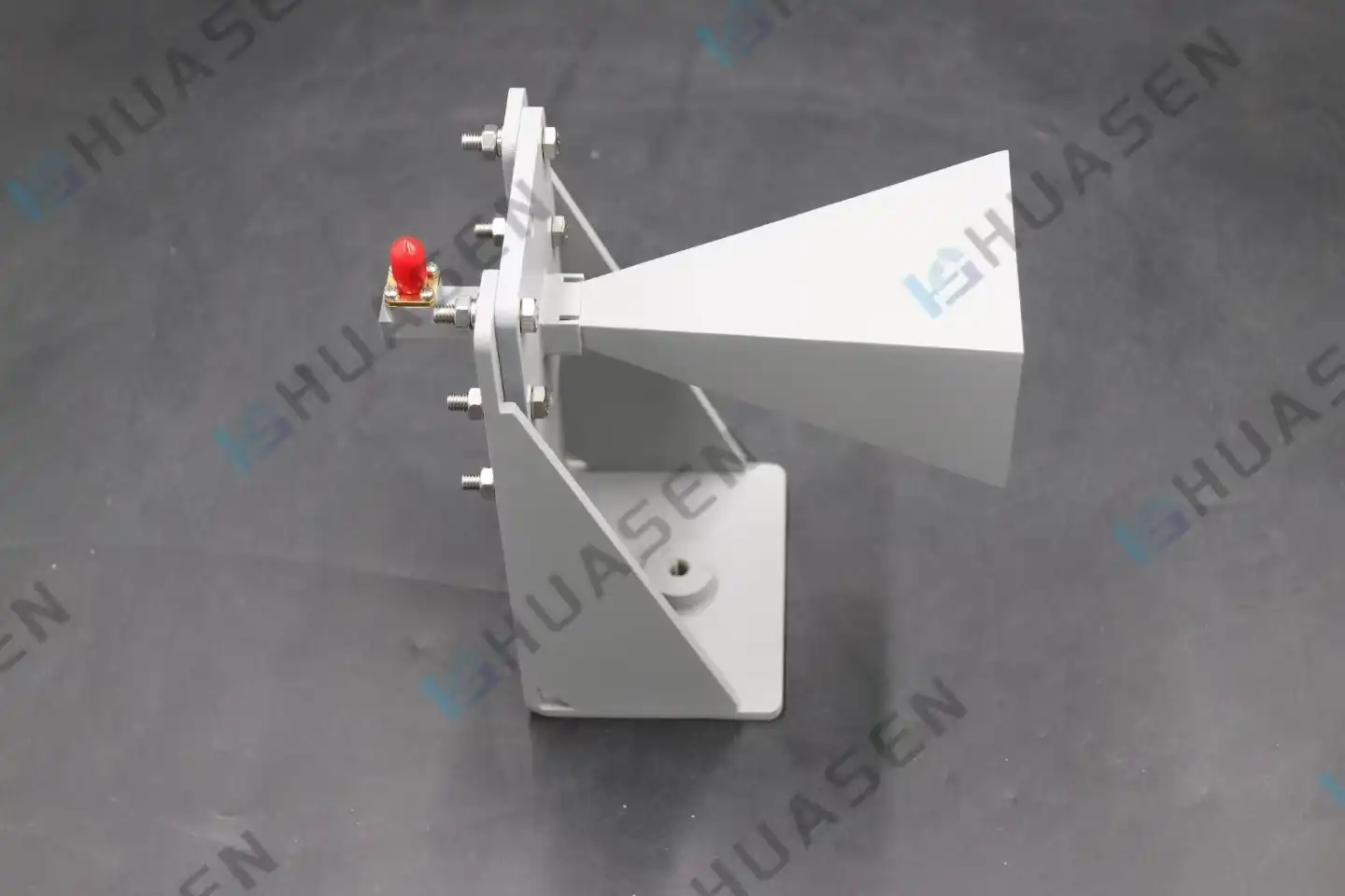
In microwave testing, a standard gain horn is the most important piece of metrology equipment. These devices are very different from regular communication antennas because the way they are shaped directly affects how well they work. They are made in the shape of pyramids or cones and work in specific waveguide bands, such as the X-band, Ku-band, or millimeter-wave ranges. Their gain values are usually between 10 and 25 dBi. The aperture sizes are based on strict mathematical relationships that have been set up in foundational sources like NRL Report 4433. This makes sure that theoretical calculations match up with measured results.
It's clear right away how valuable these horns are when we use them in our calibration labs. The thing solves the measurement uncertainty problem by being a "known good" reference. Without this reference, it's more like guesswork than science to describe unknown antennas or confirm the performance of an anechoic chamber.
Operating Principles That Enable Measurement Traceability
Controlled electromagnetic field expansion is what these standard gain horn antennas are based on in terms of physics. RF energy comes in through a waveguide flange, which is usually a WR-type or precision coaxial adapter, and spreads out through the flared aperture. The beam's characteristics are set by the flare angle and length, and its directivity is controlled by the aperture size. It is important to be able to accurately measure field strength because this relationship makes it possible to predict radiation patterns with clean main lobes and suppressed sidelobes.
Another important trait is the purity of the polarization. Cross-polarization levels in these horns are usually less than -30 dB, and they keep linear polarization throughout their operating bandwidth. When testing new phased arrays or dual-polarized base station antennas, this trait is very important because polarization discrimination has a direct effect on how well the system works.
Frequency Coverage and Application Scope
Coverage ranges depend on which waveguide band is chosen. A Ka-band unit works from 26.5 GHz to 40 GHz, while an X-band unit may work from 8.2 GHz to 12.4 GHz. Compared to multi-octave antennas, this band-specific design is more accurate. The smaller bandwidth makes it easier to control VSWR, the consistency of the radiation pattern, and gain flatness. These are all factors that have a direct impact on calibration uncertainty budgets.
Key Design and Performance Parameters Impacting Calibration Accuracy
Aperture Geometry and Gain Calculation
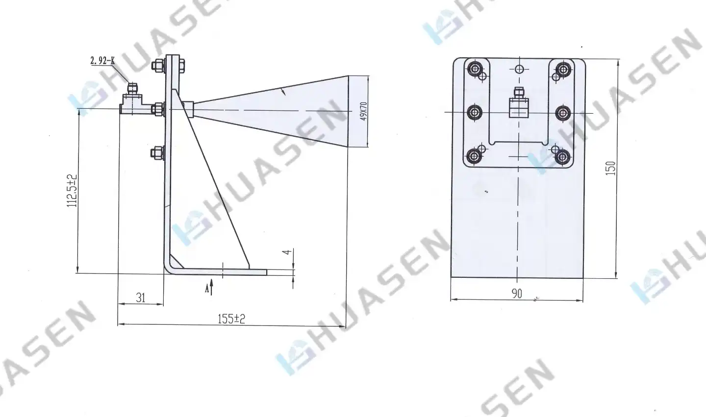
The performance of a horn is based on its aperture dimensions. The width, height, and pyramidal flare work together to make a useful radiating area that determines the direction. To figure out the gain, use the formula G = (4π × A × η) / λ², where A is the aperture area, η is the aperture efficiency (usually 50–60% for standard horns), and λ is the wavelength. Because of this mathematical predictability, calibration chains can be tracked and are recognized by accreditation bodies all over the world.
Tolerances in manufacturing are very important here, especially for a standard gain horn antenna. Even small changes in the size of the aperture (within 0.5 mm for microwave frequencies) can cause the gain curves to move too far from what is considered acceptable. Reference-grade horns are different from general-purpose devices because they are made with more precision and go through quality control steps.
Material Selection and Waveguide Construction
The materials used affect both how well they conduct electricity and how stable they are over time. The horn's body is made of a high-conductivity metal, like aluminum alloy or brass. The surface is treated to stop oxidation, which could change the reflection coefficients. To keep current paths from getting messed up and unwanted radiation modes from being created, internal surfaces need to be finished with care.
Pay close attention to the area where the waveguide meets the horn. When impedance changes quickly, reflections happen, which raises VSWR and lowers the accuracy of the measurement. Well-designed standard gain horn antennas have gradual tapers and exact matching sizes, which let them achieve VSWR values below 1.2:1 across the entire operating band. This low return loss makes sure that the most power is transferred and that multipath interference is kept to a minimum in test environments.
Connector Standards and Interface Compatibility
Specifications for interfaces have a direct effect on how systems are integrated. Waveguide flanges must meet strict size requirements, such as UG-series or IEC standards. This makes sure that connections can be made over and over again without air gaps that change insertion loss. Specifications for torque and bolt patterns are based on written steps that are repeated by calibration technicians during uncertainty analysis.
Connector wear is a real problem for calibration labs that get a lot of use. Repeated connections wear down contact surfaces over time, which causes measurement drift. Good horns have hardened flange materials and precision-ground mating surfaces that can connect and disconnect thousands of times without losing their electrical integrity.
Calibration Techniques Using Standard Gain Horn Antennas
Establishing the Reference Measurement Chain
The main calibration method is the gain transfer method. First, we set up two standard gain horn antennas that are exactly the same in a test range with a known distance between them. The Fraunhofer distance formula R = 2D²/λ finds the smallest distance between two points, where D is the largest aperture dimension. When you work closer than this, near-field effects happen that make measurements less accurate.
Power is sent from a signal generator to the receive horn, which is connected to a power meter. The power travels through space and arrives at the receiving horn. The Friis transmission equation, P_r = P_t + G_t + G_r - L_path, shows how these parameters are related. Path loss L_path = 20log(4πR/λ) shows how attenuation changes with distance. The system sets a clear reference level because both horns have known, equal gains.
Characterizing the Antenna Under Test
After setting the reference baseline, we switch out one standard gain horn antenna for the device being tested while keeping the measurements and geometry the same. By simple substitution, the change in received power shows directly what the unknown antenna's gain is. Many systematic errors can't happen with this method because changes in transmitter output, cable losses, and effects of the atmosphere affect both measurements in the same way.
Controls over the environment make it easier to repeat. When the temperature stays within ±2°C, thermal expansion doesn't happen, which changes the path length and alignment. Keeping the relative humidity below 60% reduces the amount of water vapor that is absorbed at millimeter-wave frequencies. When these controls are used with electromagnetic shielding to block out outside interference, measurement uncertainty budgets are kept below 0.5 dB for calibrations that are done correctly.
Standards Compliance and Certification Requirements
Calibration procedures are governed by well-known standards. ISO/IEC 17025 sets general standards for testing and calibration labs. It does this by describing quality management systems and criteria for technical competence. IEEE Standard 149-1979 talks about antenna measurements in detail, giving advice on range configurations, uncertainty analysis, and how to keep records.
Being able to trace something back to a national metrology institute, like NIST in the US, gives you the utmost confidence. Labs that are accredited keep their calibration chains intact, connecting their standard gain horn antenna to primary standards through documented transfers in the middle. This is very important for industries like aerospace and defense, where measurement error has a direct effect on system safety and following the rules.
Comparing Standard Gain Horn Antennas with Other Antenna Types for Calibration
Advantages Over Broadband Horn Designs
Multi-octave bandwidth is achieved by double-ridged horns, which have internal ridge structures that change the way fields are distributed. Even though the wider coverage seems like a good thing, the design flaws cause gain ripple, which are changes in frequency that happen over time and make calibration less accurate. Uncertainty budgets for wideband horns are usually higher than 1.5 dB, while standard gain horn antenna designs can only handle 0.3 to 0.5 dB.
When things are put into practice, the trade-off becomes clear. A company that makes communications equipment might first look at a single broadband horn that covers 3.3–4.2 GHz when testing 5G base station antennas across the n77 and n78 bands. But using standard gain horn antennas that are made for each frequency range leads to more accurate measurements, smaller test margins for production, and higher yield rates. The extra cost of having more than one reference horn pays off in fewer warranty claims and failures in the field.
Log-Periodic Arrays in Settings for Calibration
Log-periodic antennas have a very wide bandwidth because they have many resonant elements that are arranged in a geometric progression. These antennas are often used in EMC immunity testing because their consistent impedance and radiation patterns make it easier to set up tests across frequency ranges that span decades. But their phase center moves with frequency, which causes problems with measurements when precision gain characterization is being done.
It is very important for coherent measurements and beamforming characterization that standard gain horn antennas keep fixed phase centers within their narrower operating bands. Beam steering precision is based on phase accuracy when massive MIMO antenna arrays are being tested for 5G infrastructure. It is now necessary to have reference antennas with stable phase centers.
Parabolic Reflector Systems for High-Gain Applications
Through large apertures and focused geometries, parabolic reflectors make gains that are very high (30 dBi to 60 dBi). These traits are useful for satellite ground stations and radio astronomy applications. However, mechanical complexity makes calibration harder. Performance repeatability is affected by how accurately the feed is placed, how good the reflector surface is, and how much the structure bends under gravity.
Because they are made of a single piece and can support themselves, standard gain horn antennas get rid of these variables. A 20 dBi standard gain horn antenna has the same level of uncertainty as a parabolic system, but it takes up less space and doesn't need to be aligned. This makes it easier to use, which means lower costs and faster measurement throughput in production settings.
Procurement Considerations for Acquiring Standard Gain Horn Antennas
Evaluating Technical Specifications Against Application Needs
Costly mistakes can be avoided by matching horn specs to their intended use. A company that is putting together radar systems and making X-band weather radar needs horns that can handle high power—possibly 1 kW of continuous wave for testing immunity. On the other hand, a 5G research lab that is studying millimeter-wave phased arrays at 28 GHz values small size and accurate radiation patterns, more than power capacity.
Specifications for gain accuracy should be carefully looked over. Most commercial needs are met by standard gain horn antennas that are calibrated to within 0.5 dB of accuracy. However, military and aerospace uses may need ±0.3 dB or tighter. The calibration certificate should be based on well-known standards and have radiation pattern plots that show the sidelobe levels and beamwidth specifications.
Supplier Assessment and Quality Indicators
Well-known companies keep design histories and statistical process controls that make sure consistency from batch to batch. Ask for quality documents like material certifications, dimensional inspection reports, and network analyzer measurements when you are evaluating suppliers. Sellers with a good reputation give full test data instead of just specification sheets.
Lead times are very different depending on the frequency band and the level of customization needed. Standard X-band or Ku-band standard gain horn antennas usually ship in four to six weeks. However, it may take twelve weeks or longer for specialized millimeter-wave designs or units that meet MIL-STD requirements. To keep project schedules and inventory costs in balance, it's important to be clear with suppliers about production capacity and options for speeding up work.
Total Cost of Ownership Analysis
The initial purchase price is only one part of the investment equation. For a standard gain horn antenna, calibration intervals, which are usually once a year or every two years, depending on how often the equipment is used, create ongoing costs that build up over its lifetime. Over the course of ten years, a $3,000 standard gain horn antenna that needs to be calibrated every two years will cost a total of $7,000.
In competitive markets, vendors stand out by offering warranty coverage and support after the sale. Manufacturers who offer warranties that cover both mechanical damage and electrical drift are sure that their products will last. Being able to get technical support helps fix integration problems and make measurement setups work better, which cuts down on downtime that slows down lab work and costs money.
Conclusion
For accurate calibration, you need reference standards that work the same way every time, no matter what the conditions are. This need is met by standard gain horn antennas, which are made in a way that is based on physics and geometry. Their stable polarization, predictable radiation patterns, and calculable gains give measurements confidence that spreads through entire RF testing infrastructures. These horns are the metrological foundation that connects measurements to international standards. They are used to validate 5G base stations, describe satellite payloads, and make sure that EMC rules are followed. By balancing technical specifications, supplier capabilities, and total ownership costs when making procurement decisions, labs can stay ahead of the competition by making sure measurements are accurate and operations run smoothly.
FAQ
1. What frequency ranges do standard gain horns typically cover?
Coverage depends on which waveguide bands are chosen. Ranges that are often used are L-band (1-2 GHz), S-band (2-4 GHz), C-band (4-8 GHz), X-band (8-12 GHz), Ku-band (12-18 GHz), K-band (18-27 GHz), Ka-band (27-40 GHz), and for millimeter-wave applications, V-band and W-band. To keep the VSWR and gain ripple as low as possible, each band needs its own standard gain horn antenna design that is optimized for that frequency range.
2. How often do calibration horns need to be certified again?
Based on how often it is used, ISO 17025 guidelines say that the calibration should be done every one to three years. High-volume production labs that take measurements every day should recalibrate once a year. Research institutions that only use their instruments sometimes may extend the time between recalibrations to 24 to 36 months. Environmental factors like changing temperatures, high humidity, and worn-out connectors can speed up drift, which could mean that it needs to be checked more often.
3. Can high power be put on these horns to test for immunity?
Standard gain horn antennas do work well with a lot of power because they are simple and don't have any internal dielectrics or matching networks that would make them less powerful. Most air-filled waveguide designs can handle continuous wave power up to a few kilowatts, with breakdown voltage at the flange interface or inside the aperture being the main limit. Peak power ratings are often ten times or more higher than average power ratings. This makes them good for testing pulsed radar and EMC immunity according to MIL-STD-461 or IEC 61000-4-3 standards.
Partner With Huasen Microwave for Your Standard Gain Horn Antenna Requirements
Every standard gain horn antenna that Huasen Microwave makes is backed by more than 30 years of experience in RF engineering. Our carefully crafted designs meet the strict calibration needs of the defense, aerospace, and telecommunications industries. Each unit comes with full test data and a record of its provenance. Whether you need millimeter-wave calibration standards for satellite ground stations or X-band reference horns for testing 5G, our technical team works directly with your engineers to find the best solutions that fit your measurement uncertainty budgets and the conditions of the environment. We know that dependable suppliers do more than just deliver goods; they also offer ongoing support that makes the most of your investment. When you email sales@huasenmicrowave.com with a question, our sales team quickly answers with detailed quotes, technical specs, and customization options that fit your buying needs. As a well-known provider of standard gain horn antennas, we keep a wide range of stock on hand for popular frequency bands and can speed up production for specific needs. Get in touch with us right away to talk about your calibration needs and see for yourself why system integrators and testing labs around the world trust Huasen Microwave's quality and service.
References
1. Balanis, Constantine A. "Antenna Theory: Analysis and Design." Fourth Edition, John Wiley & Sons, 2016.
2. Institute of Electrical and Electronics Engineers. "IEEE Standard Test Procedures for Antennas." IEEE Std 149-1979 (Reaffirmed 2008).
3. National Institute of Standards and Technology. "Microwave and Millimeter-Wave Calibration Services." NIST Technical Note 1297, 1994 Edition.
4. International Organization for Standardization. "General Requirements for the Competence of Testing and Calibration Laboratories." ISO/IEC 17025:2017.
5. Hollis, J. S., Lyon, T. J., and Clayton, L. "Microwave Antenna Measurements." Scientific-Atlanta, Technical Report, 1985.
6. European Cooperation for Accreditation. "Guidelines on the Calibration of Antennas and Antenna Measurements." EA-10/12, Revision 2020.
Send Inquiry