DC Power Amplifier vs RF Amplifier: Core Differences






2026-07-20 16:01:28
When specifying amplification equipment for mission-critical systems, understanding the fundamental distinction between a DC power amplifier and an RF amplifier becomes paramount. A DC power amplifier processes signals from DC (zero frequency) through low-frequency AC ranges, delivering precise voltage and current control with minimal noise—ideal for testing equipment and laboratory instrumentation. Conversely, RF amplifiers handle radio frequency signals spanning megahertz to gigahertz ranges, designed explicitly for wireless transmission, radar detection, and telecommunications infrastructure. These devices differ profoundly in circuit topology, impedance characteristics, and operational bandwidth, making proper selection essential for system performance and procurement efficiency.
Introduction
Power amplifiers serve as the backbone of modern industrial and scientific systems, transforming low-level signals into robust outputs capable of driving demanding loads or transmitting data across vast distances. Within this broad category, two distinct amplifier families address fundamentally different engineering challenges: DC power amplifiers engineered for precision instrumentation and control, and RF amplifiers optimised for high-frequency signal transmission.
The distinction matters considerably to procurement professionals tasked with specifying components for 5G infrastructure, satellite ground stations, radar installations, or laboratory test systems. Selecting an inappropriate amplifier type can result in signal degradation, system instability, costly redesigns, and project delays. This comprehensive analysis walks through the technical foundations, performance characteristics, and practical applications of both amplifier types, equipping system integrators and equipment manufacturers with the knowledge needed to make informed purchasing decisions.
Our exploration addresses the complete decision-making framework—from fundamental operating principles through technical specifications, real-world applications, and procurement best practices. By the conclusion, you'll possess a clear understanding of which amplifier architecture aligns with your specific system requirements, performance expectations, and budgetary constraints.
What Are DC Power Amplifiers and RF Amplifiers?
Understanding the core functionality of each amplifier type establishes the foundation for effective component selection and system design.
DC Power Amplifier Fundamentals
A DC power amplifier functions as a precision instrumentation device that amplifies analogue input signals ranging from DC (zero hertz) through audio and low-frequency AC ranges into high-power voltage and current outputs. Operating on Class A or Class AB linear topologies, these amplifiers act as controlled voltage or current sources, essentially functioning as programmable power supplies with exceptional transient response and signal fidelity.
The defining characteristic of DC power amplifiers lies in their four-quadrant operation capability, meaning they can both source current (deliver power to a load) and sink current (absorb power returned from reactive loads). This bidirectional energy handling proves essential when driving inductive loads like electromagnetic coils or capacitive loads such as piezoelectric actuators, where stored energy returns to the amplifier during operation cycles.
RF Amplifier Architecture
RF amplifiers specialise in amplifying radio frequency signals typically spanning from 100 kHz to 40 GHz and beyond, serving as critical components in wireless communication systems, radar installations, and electromagnetic warfare equipment. These devices employ specialised circuit designs incorporating distributed elements, transmission line theory, and sophisticated impedance matching networks to maintain signal integrity across broad frequency ranges.
Unlike their DC counterparts, RF amplifiers prioritise parameters such as gain flatness, output power compression, harmonic distortion, and noise figure—specifications directly impacting transmission quality, detection range, and spectral purity. The circuit topology varies significantly based on application requirements, with Class A designs offering superior linearity for communication systems, while Class C or switched-mode designs maximise efficiency in radar pulse applications.
Signal Processing Distinctions
The fundamental difference centres on signal frequency characteristics. DC power amplifiers handle slowly varying or static signals where wavelength considerations remain irrelevant, allowing straightforward lumped-element circuit designs. RF amplifiers must account for electromagnetic wave propagation effects, where physical component dimensions approach signal wavelengths, necessitating transmission line analysis and distributed circuit techniques.
Technical Comparison: DC Power Amplifier vs RF Amplifier
A systematic comparison across critical performance parameters reveals how each amplifier type addresses distinct engineering challenges and application requirements.
Frequency Response and Bandwidth
DC power amplifiers typically offer bandwidth from DC to 200 kHz, with specialised units extending to several megahertz. This range suffices for replicating arbitrary waveforms in power supply simulation, motor drive testing, and sensor excitation applications. The bandwidth specification determines how rapidly the output can track input signal changes—critical when simulating voltage transients or load dumps in automotive electronics validation.
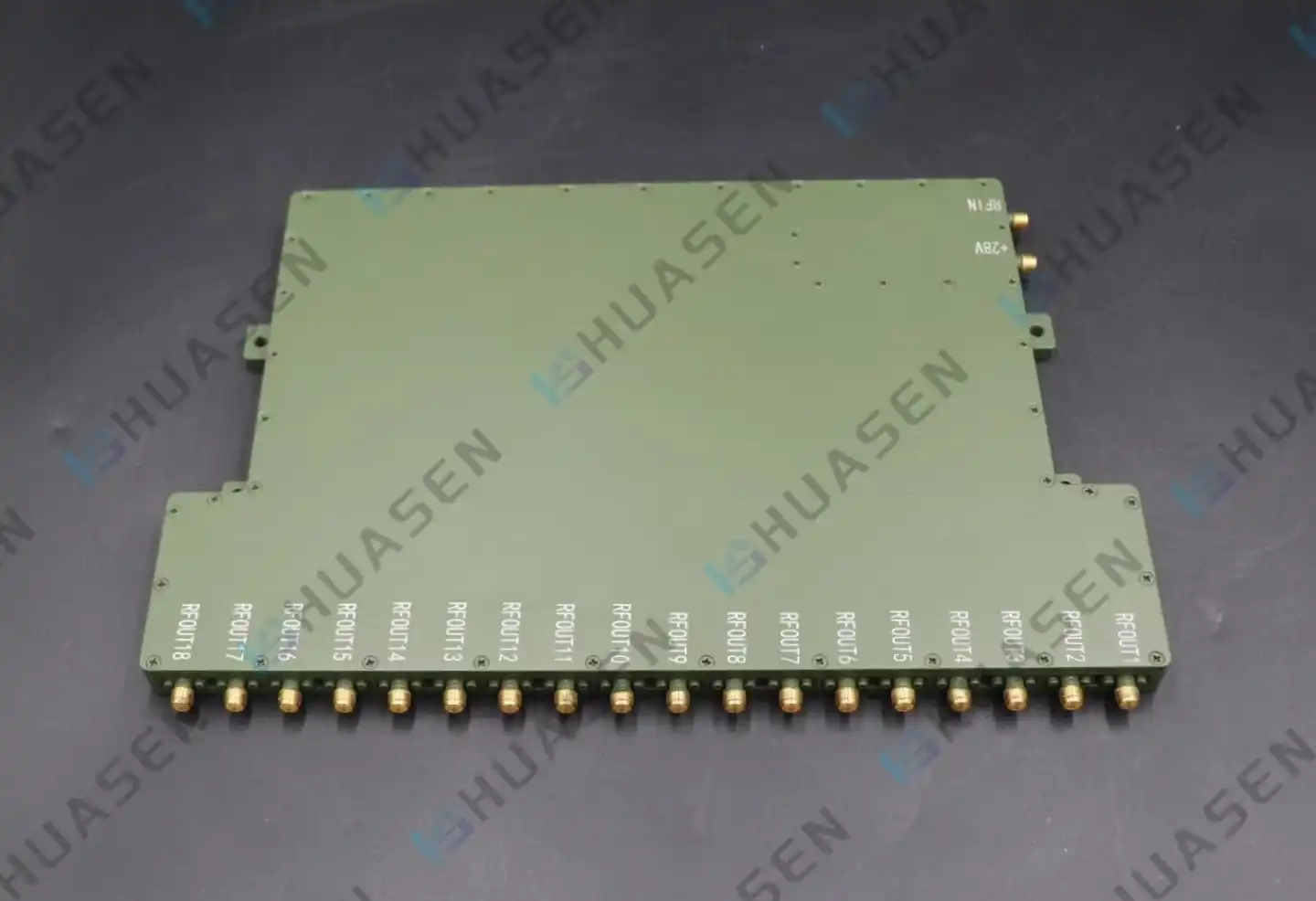
RF amplifiers operate across dramatically different frequency ranges, often spanning multiple octaves within the RF and microwave spectrum. Huasen Microwave Linear DC Power Amplifiers, specifically engineered for RF signal amplification, operate from 0.1 to 40 GHz with gain flatness typically within ±1 dB across their specified bands. This exceptional flatness ensures consistent signal amplification across wide frequency ranges, preventing amplitude distortion in wideband communication and radar systems.
| Parameter | DC Power Amplifier | RF Amplifier (Huasen Microwave) |
|---|---|---|
| Frequency Range | DC to 200 kHz (typical) | 0.1 to 40 GHz |
| Bandwidth Type | Baseband (low-pass) | Bandpass (tuned or broadband) |
| Gain Flatness | N/A (DC-coupled) | ±1 dB typical |
| Phase Linearity | Excellent (near-zero phase shift) | Critical (affects signal integrity) |
Circuit Design and Topology
Since series-pass transistors in linear regions lose excess voltage as heat, RF power amplifierand DC power amplifier circuits use linear regulation loops with intense thermal management. Low output impedance, good load regulation, and quick transient response are prioritised. Multiple feedback loops are used to ensure output stability independent of load fluctuations.
To achieve ideal load impedances across frequency ranges, RF amplifier design requires impedance matching networks using transformers, resonant circuits, or distributed matching elements. Circuit boards with controlled-impedance transmission lines (usually 50-ohm characteristic impedance) must be carefully laid up to eliminate parasitic oscillations and maintain stability under all load situations, even severe mismatches.
Power Output and Efficiency Characteristics
Modern amplifiers may deliver power in extreme ranges depending on the application. DC power amplifiers offer continuous power from watts to kilowatts with load-specific output voltage and current. Due to linear regulatory losses and large heat sinks and forced-air cooling systems, efficiency is 40-60%.
RF amplifier efficiency varies by operating class and application. Huasen Microwave's linear RF amplifiers can power laboratory test equipment and high-power transmission systems from milliwatts to kilowatts. Without extra AC-DC conversion modules, the direct DC supply design simplifies system integration and reduces failure spots.
Noise Performance and Signal Purity
DC power amplifiers decrease noise to below 10 mV rms, making them ideal for precision measurement systems and sensor calibration. The lack of switching devices avoids high-frequency ripple and electromagnetic interference that would contaminate critical electromagnetic compatibility tests or analogue signal processing measurements.
RF amplifier noise figure requirements measure how much the amplifier reduces the signal-to-noise ratio. Low-noise amplifiers receive noise numbers below 1 dB, whereas high-power amplifiers prioritise linearity and harmonic suppression. Transmissions fulfil regulatory criteria and avoid interference with neighbouring frequency channels with total harmonic distortion < 0.1%.
Load Characteristics and Stability
Handling varied load impedances is crucial. With four-quadrant operation, DC power amplifiers may absorb reactive power without harm or instability while driving resistive, capacitive, or inductive loads. This feature is essential for energising back-EMF-generating electromagnetic coils or testing battery management systems that switch between charging and discharging modes.
RF amplifiers need precise load matching to avoid damage and meet performance standards. Reflected power from severe load mismatches may harm output stages, requiring protective circuits or isolators. SWR or VSWR levels below 1.5:1 are good, whereas values around 1:1 are near-perfect matching conditions that maximise power transfer efficiency.
Applications and Use Cases: Choosing the Right Amplifier for Your Needs
Selecting the appropriate amplifier type depends entirely on your specific application requirements, operating environment, and system architecture.
DC Power Amplifier Application Scenarios
Many industrial testing labs employ DC power amplifiers for hardware-in-the-loop power supply simulation during product validation. Automotive manufacturers utilise these amplifiers to simulate battery voltage transients during engine cranking sequences to test electronic control modules under realistic electrical stress conditions that bench supplies cannot imitate.
Researchers employ DC power amplifiers to produce magnetic fields using Helmholtz coils, which need high current for inductive loads. Four-quadrant operation gracefully handles inductive kickback, and linear topology provides ripple-free current control for traceable magnetometer and Hall-effect sensor calibration. For nanometre-scale positioning in semiconductor lithography and precision optics manufacturing, capacitive loading in piezoelectric actuator driving demands amplifiers with fast charge injection and extraction.
RF Amplifier Deployment in Communication Systems
Every wireless node utilises an RF power amplifier. For macro-cell coverage, 5G base station transmitters employ high-power linear amplifiers to boost multi-carrier signals to minimise intermodulation distortion that would interfere with nearby channels. Huasen Microwave's linear RF amplifiers address this demand with excellent gain flatness and low operating spectrum distortion.
Satellite communication ground stations recover weak signals from space using low-noise receiving amplifiers and overcome uplink route loss using high-power send amplifiers. The amplifiers must work stably despite temperature fluctuations and meet rigorous harmonic emission regulations to prevent interference with satellite services utilising nearby frequency bands.
Radar and Defence Applications
Pulsed radar systems need high peak power, making amplification challenging. Transmit amplifiers must provide kilowatts or megawatts of pulsed RF power with correct pulse form and low phase noise to improve detection range and resolution. For antenna systems with ice accumulation or radome damage, the amplifiers include enhanced load-mismatch avoidance circuits.
Electronic countermeasure systems with wideband RF amplifiers may jam or confuse threat radar systems with high-power noise or deception signals. These amplifiers must respond swiftly to frequency agility commands and provide flat power throughout multi-octave bandwidths. Linear amplifiers maintain complex modulation schemes for high data rates across tens of kilometres in point-to-point microwave backhaul and wireless bridging.
| Application Domain | Preferred Amplifier Type | Key Requirements |
|---|---|---|
| Laboratory Power Supply Simulation | DC Power Amplifier | Four-quadrant operation, low noise, fast transient response |
| Base Station Transmitters (5G/6G) | Linear RF Amplifier | High linearity, gain flatness, and multi-carrier capability |
| Satellite Ground Stations | RF Amplifier (LNA + HPA) | Low noise figure (receive), high power (transmit), thermal stability |
| Radar Transmitters | Pulsed RF Amplifier | High peak power, pulse fidelity, load mismatch tolerance |
| Electronic Warfare | Wideband RF Amplifier | Broad instantaneous bandwidth, fast frequency switching |
| Precision Actuator Control | DC Power Amplifier | Capacitive load handling, low THD, high bandwidth |
Communications Testing and Instrumentation
RF testing laboratories employ signal amplifiers to boost low-level outputs from vector signal generators to power levels required for testing receiver sensitivity or conducting over-the-air performance validation. The amplifiers must exhibit excellent linearity to preserve complex modulation schemes like 256-QAM or OFDM waveforms used in modern wireless standards. Calibration laboratories utilise both DC and RF amplifiers as transfer standards, requiring exceptional long-term stability and low drift characteristics traceable to national metrology institutes.
Conclusion
The choice between DC power amplifiers and RF amplifiers hinges on fundamental application requirements—signal frequency characteristics, power delivery needs, and load impedance properties. DC power amplifiers excel in precision instrumentation, offering four-quadrant operation, ultra-low noise, and excellent stability with reactive loads, making them indispensable for laboratory testing and industrial control applications. RF amplifiers serve an entirely different purpose, amplifying high-frequency signals for wireless transmission, radar detection, and communications infrastructure with emphasis on gain flatness, linearity, and noise figure performance.
Successful procurement demands thorough specification analysis, supplier capability evaluation, and consideration of total lifecycle costs beyond initial purchase price. Huasen Microwave's three decades of specialised expertise in high-frequency component manufacturing position the company as a trusted partner for demanding telecommunications, aerospace, and defence applications requiring reliable, high-performance RF amplification solutions with comprehensive technical support and customisation capabilities.
FAQ
1. Can a DC power amplifier handle RF signals effectively?
DC power amplifiers typically lack the bandwidth and impedance matching networks required for efficient RF signal amplification. While some wideband DC amplifiers extend into the low megahertz range, they cannot match the performance of purpose-built RF amplifiers at higher frequencies. Attempting to use a DC amplifier for RF applications results in poor efficiency, excessive signal reflections, and potential instability. Conversely, RF amplifiers cannot process DC or very low-frequency signals due to AC coupling in their input and output stages.
2. What maintenance practices extend amplifier operational life?
Thermal management represents the most critical maintenance consideration. Ensure cooling air pathways remain unobstructed and clean filters regularly in forced-air cooling systems. Monitor operating temperatures and investigate any increases that suggest degraded thermal interface materials or fan failures. Periodically verify output performance against datasheet specifications to detect gradual degradation. Protect amplifiers from load mismatches and environmental contamination, particularly in outdoor installations where moisture ingress can cause corrosion and dielectric breakdown.
3. How do I select between high-efficiency and high-linearity RF amplifier designs?
The selection depends on your modulation scheme and spectral purity requirements. Communication systems employing complex modulation with high peak-to-average power ratios require linear amplifiers (Class A or AB) despite lower efficiency to prevent signal distortion. Constant-envelope modulation schemes like FM or simple pulsed radar can utilise more efficient designs (Class C or switched-mode) that sacrifice linearity for improved power conversion efficiency. Evaluate your specific signal characteristics and adjacent-channel interference requirements when making this tradeoff decision.
Partner with Huasen Microwave for Superior RF Amplification Solutions
Specifying the right amplifier technology protects your system investment and ensures optimal performance throughout the operational lifecycle. Huasen Microwave Technology Co., Ltd. combines three decades of high-frequency component expertise with comprehensive customisation capabilities, delivering linear DC power amplifiers engineered specifically for demanding RF applications spanning 0.1 to 40 GHz. Our direct DC supply architecture and exceptional gain flatness make us a preferred DC power amplifier supplier for telecommunications infrastructure, radar systems, and aerospace applications requiring uncompromising reliability.
Contact our technical team at sales@huasenmicrowave.com to discuss your specific amplification requirements, request detailed datasheets, or arrange sample evaluation. Our engineering staff provides design assistance, helping you optimize specifications for your unique application constraints while managing costs effectively.
References
1. Cripps, S. C. (2006). RF Power Amplifiers for Wireless Communications (2nd ed.). Artech House Publishers.
2. Kazimierczuk, M. K. (2015). RF Power Amplifiers (2nd ed.). John Wiley & Sons.
3. Sevick, J. (2001). Transmission Line Transformers (4th ed.). Noble Publishing.
4. Grebennikov, A., Sokal, N. O., & Franco, M. J. (2012). Switchmode RF and Microwave Power Amplifiers (2nd ed.). Academic Press.
5. Raab, F. H., et al. (2002). "Power amplifiers and transmitters for RF and microwave." IEEE Transactions on Microwave Theory and Techniques, 50(3), 814-826.
6. Agilent Technologies. (2009). Fundamentals of RF and Microwave Power Measurements. Application Note 64-1A.
Send Inquiry