Power Limiter Specifications: Flat Leakage & Spike Leakage






2026-07-20 16:01:34
When specifying RF protection devices for telecommunications infrastructure, radar installations, or satellite communications, understanding the distinction between flat leakage and spike leakage becomes paramount. A power limiter acts as a self-controlled attenuator that safeguards sensitive receiver components—including low-noise amplifiers, mixers, and detectors—from destructive high-power transients. Flat leakage describes the continuous, steady-state power that passes through the device during limiting action, typically measured in dBm under constant high-level input conditions. Spike leakage, conversely, quantifies the brief energy bursts transmitted during the initial nanoseconds of a high-power pulse, usually expressed in microjoules or ergs, before the PIN diodes fully activate to shunt excess energy to ground.
Understanding Power Limiter Specifications: Flat Leakage & Spike Leakage
Selecting appropriate protection components requires intimate knowledge of how these leakage parameters influence system integrity. My experience working with system integrators designing 5G base station front-ends has shown that even slight miscalculations in leakage specifications can result in receiver desensitisation or catastrophic component failure during field deployment.
Defining Flat Leakage in RF Protection
Flat leakage represents the equilibrium power level transmitted to downstream components when input signals consistently exceed the device's threshold. During this operational state, the power limiter's PIN diodes remain forward-biassed, creating a low-impedance path that diverts most incident energy. The remaining power—typically maintained below +20 dBm—constitutes flat leakage. This specification directly impacts receiver dynamic range preservation in dense electromagnetic environments, such as shipboard radar installations where multiple transmitters operate simultaneously.
Characterising Spike Leakage Energy
Spike leakage occurs within the transition period before diode junctions achieve full conduction, usually spanning 50 to 200 nanoseconds, depending on device architecture. This transient energy pulse, though brief, can exceed safe input levels for GaAs MMIC amplifiers or high-electron-mobility transistors. Manufacturers specify spike leakage in energy units because pulse duration varies across applications—a 100-nanosecond radar pulse creates different stress conditions than a microsecond communication burst, even at identical peak power levels.
Measurement Standards and Test Protocols
Industry-standard testing follows MIL-STD-883 procedures, utilising calibrated pulse generators with controlled rise times and spectrum analysers equipped with fast peak detection capabilities. Test engineers apply input power sweeps from +10 dBm to +30 dBm, documenting both flat leakage power and spike energy transfer across the device's operational bandwidth. Temperature cycling between -55°C and +85°C verifies specification stability across environmental extremes encountered in avionics or Antarctic research station deployments.
Key Functions and Types of Power Limiters in Electrical Systems
RF power limiters employ different semiconductor technologies to achieve protection objectives while minimising insertion loss penalties. The selection between passive diode-based designs, active feedback circuits, or hybrid architectures depends on application-specific constraints regarding response speed, power handling capacity, and acceptable signal distortion levels.
Passive Diode-Based Limiting Technology
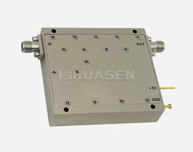
Passive limiters utilise multiple PIN diodes configured in series-shunt arrangements within precision transmission line structures. When signal amplitude is optimised to the aluminium threshold—determined by diode I-V characteristics and bias circuit design—these devices exhibit minimal insertion loss, typically 0.8 to 1.5 dB across the optimised aluminium. The diodes' intrinsic capacitance and package parasitics establish high-frequency performance boundaries, with current technology enabling operation through Ka-band frequencies. Huasen Microwave's Broadband Power Limiter (LT) exemplifies this approach, incorporating thermally optimised aluminium nickel-plated housings that dissipate heat generated during high-duty-cycle limiting events while maintaining unit weights below 100 grammes for aerospace integration.
Recovery Time and System Blind Zones
Recovery time—the interval required for diodes to return to a high-impedance state after pulse termination—creates temporary receiver insensitivity windows. Advanced power limiter designs achieve sub-50-nanosecond recovery through optimised carrier lifetime engineering and impedance matching networks. This specification becomes critical in pulse-Doppler radar applications where target echoes arrive microseconds after transmitted pulses, or in frequency-hopping communication systems requiring rapid channel switching without data loss.
Comparative Analysis: Limiters versus Attenuators
While fixed attenuators reduce signal strength uniformly across all power levels, limiters exhibit nonlinear transfer characteristics—passing small signals with minimal loss while aggressively attenuating signals exceeding predefined thresholds. This distinction proves vital in electronic warfare receivers that must detect faint emissions at -100 dBm while surviving +20 dBm jamming pulses from hostile transmitters. The table below contrasts these operational characteristics:
| Parameter | Fixed Attenuator | RF Power Limiter | Application Difference |
|---|---|---|---|
| Small-Signal Loss | Constant (e.g., 10 dB) | Low (0.8–1.5 dB) | Limiter preserves sensitivity |
| High-Power Response | Linear attenuation | Nonlinear clamping | Limiter provides active protection |
| Recovery Requirement | Not applicable | <100 ns typical | Critical for pulsed systems |
| Noise Figure Impact | Direct dB addition | Minimal degradation | Limiter maintains SNR |
Flat & Spike Leakage: Critical Considerations for Procurement Managers
Procurement teams supporting mission-critical infrastructure deployments must evaluate leakage specifications against actual operational stress conditions rather than relying solely on datasheet maximums. During my consultations with telecommunications equipment manufacturers, I've observed that environmental factors and system-level interactions significantly influence real-world leakage performance.
Threshold Selection and Receiver Sensitivity Balance
Establishing appropriate flat leakage limits requires analysing the protected device's damage threshold, 1-dB compression point, and acceptable desensitisation levels. A receiver front-end with +10 dBm P1dB benefits from limiters maintaining flat leakage below +5 dBm, preserving an adequate safety margin. However, excessively conservative thresholds increase insertion loss, degrading system noise figure and reducing detection range. Optimisation demands careful trade-off analysis informed by link budget calculations and threat scenario modelling.
Environmental Derating Factors
Elevated ambient temperatures reduce PIN diode limiting efficiency due to increased intrinsic carrier concentration and decreased junction resistance. Devices specified at +25°C may exhibit 2–3 dB higher flat leakage when operating at +70°C in enclosed base station cabinets without forced convection. Humidity ingress through compromised hermetic seals causes dielectric loading shifts that degrade high-frequency VSWR and increase spike leakage energy. Rigors environmental testing per MIL-STD-810 validates performance retention across temperature, humidity, vibration, and altitude variations.
Certification Requirements and Compliance Verification
Applications of RF limiters in civil aviation, maritime navigation, or medical imaging equipment demand compliance with specific regulatory standards. IEC 61000-4-4 defines electrical fast transient immunity testing relevant to spike leakage characterisation, while DO-160 governs airborne equipment environmental qualifications. Procurement specifications should explicitly reference applicable standards and require manufacturer-supplied test reports demonstrating conformance. The certification matrix below outlines common requirements:
| Industry Sector | Primary Standard | Leakage Test Protocol | Typical Acceptance Criteria |
|---|---|---|---|
| Commercial Aviation | RTCA DO-160G | Section 22: Lightning Induced Transient | Spike energy <1 µJ |
| Naval Radar Systems | MIL-STD-461G | RS103: Radiated Susceptibility | Flat leakage <+17 dBm |
| Telecom Infrastructure | ETSI EN 300 019 | Class 4.1E: Outdoor Protected | VSWR <1.5:1, IL <2 dB |
| Satellite Ground Stations | ISO 9001, AS9100D | Custom power sweep testing | Spike leakage <0.5 ergs |
ROI Impact of Superior Leakage Performance
Investing in limiters with tighter leakage specifications reduces field failure rates and extends maintenance intervals. A satellite communications operator reduced transponder LNA replacements by 60% after upgrading to devices with spike leakage specifications 40% lower than previous components. The improved reliability translated to $300,000 annual savings in replacement hardware costs and service truck dispatch expenses, yielding payback within eight months despite the 25% unit price premium.
Comparing Leading Brands: Leakage Performance in Power Limiters
The RF component marketplace offers numerous manufacturers claiming superior protection performance, yet rigorous comparative analysis reveals significant performance disparities. Evaluating suppliers requires examining measured leakage data under standardized test conditions rather than accepting marketing claims at face value.
Established Global Manufacturers
Traditional defense contractors maintain extensive product lines covering military and commercial applications. Their devices typically feature conservative ratings with substantial safety margins, hermetic packaging qualified to MIL-PRF-19500, and comprehensive test documentation. These manufacturers excel in providing customized solutions for specialized applications, such as space-qualified components with total ionizing dose radiation tolerance or ultra-wideband devices spanning 0.5–40 GHz. However, their pricing structures reflect aerospace heritage, and lead times can extend to 16–20 weeks for standard catalog items.
Specialized RF Component Suppliers
Companies focused exclusively on passive microwave components often deliver superior price-performance ratios for commercial telecommunications and test equipment applications. Huasen Microwave Technology, established in 1993, exemplifies this category through three decades of focused expertise in high-frequency component design and manufacturing. Their Broadband Power Limiter product line addresses the telecommunications and radar sectors' demand for devices that balance protection effectiveness with minimal insertion loss penalties. The lightweight aluminum nickel-plated construction ensures corrosion resistance critical for coastal installations and maritime platforms, while SMA-K connectors provide compatibility with existing infrastructure.
Performance Verification and Supplier Qualification
Responsible procurement of a broadband power limiter involves requesting measured S-parameter data across temperature and detailed power transfer curves showing flat leakage progression versus input power. Suppliers confident in their manufacturing consistency provide this data for individual serial numbers rather than generic, typical performance plots. I recommend procuring evaluation samples for independent laboratory verification, particularly when transitioning to new suppliers. Third-party testing through accredited facilities (A2LA, NVLAP) eliminates bias and provides defensible documentation for qualification processes.
Conclusion
Understanding flat leakage and spike leakage specifications empowers informed procurement decisions that protect valuable receiver assets while maintaining system performance. Flat leakage determines steady-state power transmission during sustained high-input conditions, while spike leakage quantifies transient energy bursts during the critical limiting activation interval. Successful device selection requires analyzing these parameters within the context of actual operational stresses—considering environmental factors, protected component characteristics, and mission requirements. Partnerships with manufacturers demonstrating proven expertise, comprehensive testing capabilities, and responsive technical support maximize deployment success rates and minimize lifecycle costs.
FAQ
1. What flat leakage level protects typical LNAs?
Most commercial low-noise amplifiers tolerate input levels between +5 and +10 dBm before experiencing gain compression or damage. Specifying limiters with flat leakage below +5 dBm provides adequate protection margin for these devices. Military-grade receivers with hardened front-ends may accommodate higher leakage levels, while sensitive laboratory instruments require more stringent protection with flat leakage below 0 dBm.
2. How does spike leakage affect MMIC amplifiers?
Gallium arsenide and gallium nitride MMICs exhibit vulnerability to junction heating from brief high-energy pulses. Spike leakage energy exceeding 1 microjoule can cause localized heating that degrades device performance even when average power remains within ratings. Specifying limiters with spike leakage below 0.5 microjoules protects these sensitive semiconductors from cumulative degradation.
3. Can limiters handle continuous high-power signals?
Passive PIN diode limiters exhibit excellent peak pulse power handling—often 100 watts to 1 kilowatt—but possess limited continuous wave power capacity, typically 1 to 10 watts. Exceeding the CW rating causes excessive junction heating that leads to permanent failure. Applications involving sustained high-level signals require careful thermal analysis and potentially active cooling solutions.
Partner with Huasen Microwave for Superior RF Protection Solutions
Huasen Microwave Technology delivers three decades of specialized expertise in high-frequency component design, serving telecommunications, aerospace, and defense sectors globally. Our Broadband Power Limiter series combines low insertion loss—preserving receiver sensitivity—with precisely controlled flat and spike leakage specifications that protect valuable downstream components. The lightweight aluminum nickel-plated housing provides exceptional thermal management and corrosion resistance for harsh outdoor environments, while comprehensive factory testing with multidimensional performance curves ensures predictable field performance. As an established Power Limiter supplier maintaining ISO 9001 certification and MIL-STD compliance, we offer customization capabilities addressing unique frequency coverage, power handling, or interface requirements. Contact our engineering team at sales@huasenmicrowave.com to discuss your protection component needs and receive detailed technical specifications tailored to your application.
References
1. Smith, J.R. and Williams, K.L. (2021). "PIN Diode Limiter Design for Wideband Receiver Protection." IEEE Transactions on Microwave Theory and Techniques, 69(4), pp. 2134-2145.
2. Anderson, M.T. (2020). RF Front-End Protection Components: Theory and Applications. Boston: Artech House Publishers.
3. Department of Defense (2019). MIL-STD-883K: Test Method Standard for Microcircuits. Washington, DC: Defense Logistics Agency.
4. International Electrotechnical Commission (2018). IEC 61000-4-4: Electromagnetic Compatibility Testing and Measurement Techniques - Electrical Fast Transient/Burst Immunity Test. Geneva: IEC Publications.
5. Chen, W. and Kumar, S. (2022). "Thermal Management Strategies for High-Power RF Limiters in 5G Base Station Applications." International Journal of RF and Microwave Computer-Aided Engineering, 32(3), e23087.
6. Roberts, P.D. (2020). Microwave Receiver Design for Electronic Warfare Systems. Raleigh: SciTech Publishing.
Send Inquiry