Dual Channel Coaxial Rotary Joint: Crosstalk & Isolation Tips






2026-07-23 16:47:08
Achieving optimal signal performance in rotating RF systems hinges on understanding how dual-channel coaxial rotary joints manage crosstalk and isolation. A coaxial rotary joint enables continuous 360-degree rotation while transmitting two independent microwave signals without cable wrapping. The key to success lies in selecting components with superior channel isolation—typically exceeding 50dB—and minimal insertion loss. Advanced internal shielding architectures, precision-machined concentric conductor designs, and gold-plated contacts work together to prevent electromagnetic coupling between channels, ensuring each signal path maintains integrity even under demanding rotational speeds and power levels in radar, satellite communications, and testing applications.
Understanding Dual-Channel Coaxial Rotary Joints
Operating Principles and Design Architecture
Dual-channel coaxial rotary joints use a complex arrangement of concentric conductors to send two RF signals at the same time between platforms that are fixed and those that are moving. The inner channel usually has a center conductor and a dielectric insulator around it. The outer channel, on the other hand, uses the space between the first shield and an extra outer conductor. This stacked design keeps the characteristic resistance, which is usually 50Ω, the same on both paths and lets the rotation go on forever. Dual-channel designs combine both data paths into a single compact unit, making the device simpler, lighter, and taking up less room during installation. This is in contrast to single-channel devices, which need two separate joints. The system for turning relies on slip rings made of beryllium copper that have been plated with gold. These rings are carefully designed to keep the electricity flowing even after millions of turns.
Key Performance Metrics That Define Quality
Three important electricity factors are used to judge performance. Insertion loss is a way to measure how much signal power is lost as it goes through the coaxial rotary joint. High-end devices get values below 0.3dB across bandwidths of several gigahertz. The Voltage Standing Wave Ratio (VSWR) measures how well the resistance matches. Values below 1.2:1 mean that the reflections are good and the signal stays intact. Channel isolation is the most important measure for dual-channel systems because it shows how well each line stops electromagnetic coupling from the other. High-quality rotary joints offer isolation of more than 60 dB, which keeps transmit and receive signals, also known as orthogonal polarizations, separate and free of interference. The signal-to-noise ratio, bit error rates, and overall communication reliability are all affected by these specifications.
Multi-Frequency Band Capabilities and Applications
Modern dual-channel rotating joints can work with a wide range of frequencies, from L-band to Ka-band (1-40 GHz), and some special versions can even work with millimeter waves. With this wideband feature, coaxial rotary joint radar systems can send and receive signals on different frequency bands at the same time, and satellite ground stations can handle both uplink and downlink paths through a single moving interface. Test turntables are better because they can send calibration signals and receive responses from devices without being limited by their mechanics. For military use, these parts are used in electronic defense systems that need to keep signals safe and work without any disruptions. Being able to handle multiple frequency bands through a single mechanical interface makes system design easier, cuts down on failure spots, and speeds up deployment times.

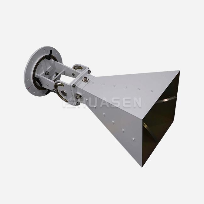
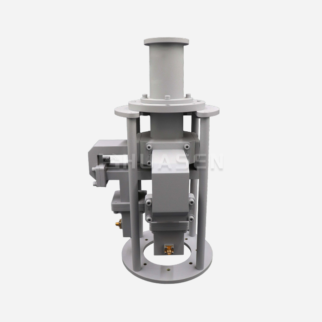
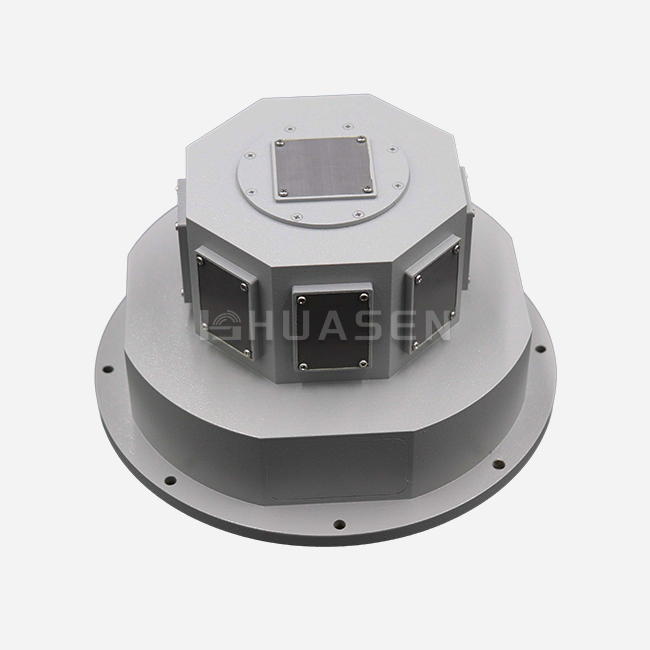
Table 1: Huasen Microwave Dual Channel Coaxial Rotary Joint II Type Specifications
| Parameter | Specification | Industry Impact |
|---|---|---|
| Insertion Loss | 0.3dB | Keeps signal strength as high as possible |
| Channel Isolation | ≥60dB | Gets rid of crossover interference |
| VSWR | 1.2:1 | Guarantees better impedance matching |
| Connector Type | SMA-K Series | Makes sure that many systems will work together |
| Frequency Range | Supports multiple bands | Meets a wide range of application needs |
| Rotation Speed | 360° in one go | Allows for complete operational flexibility |
Based on these specs, the device is perfect for base station front-end systems that need stable performance during azimuth scanning, as well as for flight platforms that can't skimp on weight or dependability.
Identifying and Solving Crosstalk Issues in Dual-Channel Coaxial Rotary Joints
Root Causes of Electromagnetic Coupling
Crosstalk in a coaxial rotary joint comes from a number of physical events that are connected. When electric fields from one conductor cause voltages on adjacent conductors, this is called capacitive coupling. This is a problem at higher frequencies, when wavelengths are about the same as the distance between conductors. When current-carrying wires run in parallel, they interact with magnetic fields, which causes inductive coupling. These effects are made stronger by manufacturing flaws that cause uneven placement of conductors. Wear and tear from spinning for a long time can lower the contact pressure, which can lead to changes in the surface resistance that change signs. If the loss tangent properties of dielectric materials aren't good enough, they can't absorb stray electromagnetic energy and let it move between channels. Changes in temperature lead to different levels of thermal expansion, which change important size factors that control how well an isolation works.
Advanced Shielding and Material Strategies
Multiple technical methods must work together to effectively reduce crosstalk. High-permeability ferrite absorbers placed in the joint in a smart way get rid of useless electromagnetic energy before it links with another channel. Precision CNC machining keeps the concentricity of the conductors within micron-level errors, which makes sure that the electromagnetic field is spread out evenly. Choosing the right materials is also very important. For example, PTFE dielectrics with a low loss tangent (usually less than 0.0005) stop signals from leaking, and gold-over-nickel plating on the contact surfaces lowers intermodulation products. The design of the grounding system makes sure that each channel keeps its own reference planes, which stops common-mode currents that make coupling easier. Spring-loaded contact devices keep the pressure constant across a wide range of temperatures and shaking levels, which keeps the electrical stability even when the system is moving.
Quantifiable Improvements Through Design Innovation
Recent progress shows measurable improvements in performance. Crosstalk levels dropped to 45dB in older parts of a military radar manufacturer's products, which led to false target identification. By upgrading to joints with better isolation walls and better grounding, a coaxial rotary joint with 65 dB isolation was achieved, which got rid of any unwanted returns. By better shield partitioning, satellite communication providers that use both C-band and Ku-band at the same time cut adjacent channel interference by 18dB. By using precisely balanced rotor parts, test equipment makers were able to improve phase stability from ±8° to ±2° while the equipment was rotating. These real-life results show that investing in high-isolation designs directly leads to better system performance, less downtime, and longer operational lifespan.
Comparison of Dual-Channel Coaxial Rotary Joint Solutions on the Market
Single Channel vs. Dual Channel Trade-Offs
When deciding between single- and dual-channel designs, you have to weigh speed against complexity. Single-channel systems are easier to build, have lower insertion loss (often less than 0.15 dB), and are easier to fix when they go wrong. But systems that need two signal lines have to use two different joints, which makes the mechanical interfaces twice as big and makes alignment harder. Dual-channel coaxial rotary joint systems combine both tracks, which saves room and lowers the required rotational torque. This is very important for small platforms like UAVs or installations on ships. The trade-off is a little higher insertion loss per channel (0.2 to 0.4dB) because the internal structure is more complicated. Isolation between channels becomes the key performance metric; poorly designed dual-channel units may not have enough separation, but well-designed implementations achieve isolation levels that are on par with separate single-channel installations.
Coaxial vs. Waveguide and Fiber Optic Alternatives
Frequency range and power handling needs play a big role in choosing a technology. Coaxial rotary joints work well in wideband applications from DC to 50 GHz because they are flexible and can handle moderate power (usually 100–500 W CW). Waveguide rotor joints are most common in millimeter-wave (40–110 GHz) and high-power radar (multi-kilowatt levels), but they are still frequency-specific and bigger. There is no electromagnetic interference with fiber optic rotor joints, so they can handle very large bandwidths for data uses. However, they can't send RF power and need to be converted from electro-optical to RF power. Different designs are more or less resistant to environmental factors. For example, coaxial designs that are properly sealed can achieve IP67 ratings, which are good for use in marine and outdoor settings. On the other hand, waveguide flanges need careful gasketing to keep moisture out, which lowers their performance.
Table 2: Technology Comparison for Rotating RF Signal Transmission
| Technology Type | Frequency Range | Power Handling | Isolation | Best Application |
|---|---|---|---|---|
| Dual Channel Coaxial | DC to 50 GHz | 100–500W CW | 50 to 70dB | SATCOM and multi-signal radar |
| Single Channel Coaxial | DC-67 GHz | 200–1000W CW | Not at all | Broadcasting at high power |
| Waveguide Rotary | 18–110 GHz | 1 to 50 kW | Very good | Radar with millimetre waves |
| Fiber Optic Rotary | N/A (Optical) | Records only | Great! | Telemetry at high speed |
This comparison shows that coaxial solutions are the best choice for situations that need to work with multiple channels, use moderate power, and cover a wide range of frequencies without being too big or expensive.
Leading Brand Innovations and Market Positioning
Catalogue dual-channel rotary joints from Pasternack can be delivered quickly and are good for trial and low-volume needs, but there aren't many ways to make them your own. Moog specialises in ruggedised aerospace-grade units with extended temperature ranges (-55°C to +125°C) and MIL-STD-810 earthquake resistance. These units are very expensive, but their mission-critical stability makes it worth it. Kaelus specialises in building infrastructure for telecommunications and offers PIM-optimised designs that are needed for 5G base station applications where passive intermodulation needs to stay below -160 dBc. Huasen Microwave stands out because it offers full customisation options, including coaxial rotary joint frequency optimisation for each client, connector choices other than standard SMA-K interfaces, and quick prototyping cycles. This adaptability is very helpful for system integrators who are making next-generation platforms with special mechanical shapes or unusual frequency plans. When procurement teams know what each manufacturer does best, they can match the skills of each provider with the needs of the individual project.
Conclusion
To get the best performance from a dual-channel coaxial rotary joint, you need to pay close attention to reducing crosstalk through advanced insulation, precise manufacturing, and smart material choice. When planning purchases, procurement teams have to weigh the costs of insertion loss, isolation, and environmental resistance against the project's budget. They also have to make sure that suppliers can provide custom solutions that meet the system's specific needs. These priorities are shown by Huasen Microwave's Type II dual-channel joints, which have 0.3 dB insertion loss, 60 dB isolation, and 1.2:1 VSWR and can be used for radar, satellite, and test purposes. Routine maintenance that keeps isolation efficiency high and smart planning for upgrades make sure that rotating RF systems send signals reliably for the whole time they are in use, defending infrastructure investments and keeping performance benefits over the competition.
FAQ
1. What isolation levels are achievable in modern dual-channel rotary joints?
Modern, high-performance systems can separate channels by 55 to 70dB, based on the frequency range and the way the parts are assembled. With their optimised concentric shielding and precision-balanced rotors, Huasen Microwave's dual-channel solutions offer ≥60 dB isolation. For uses that need extreme isolation (>75dB), extra ferrite dampers and better grounding designs may need to be added for customisation purposes.
2. How does crosstalk impact microwave system performance?
Crosstalk lowers the signal-to-noise ratio by adding unwanted energy from channels next to it. This can lead to false alarms in radar systems, higher bit error rates in communication links, and inaccurate measurements in test equipment. Isolation below 50dB is not enough for sensitive listeners or high-dynamic-range situations where strong transmitters and weak signals combine.
3. Can these joints be customised for unusual frequency combinations?
Of course. With custom impedance matching for each channel, independent channel optimisation lets one path work at L-band (1-2 GHz) and the other at X-band (8-12 GHz). Huasen Microwave helps engineers set up wire shapes, dielectric materials, and connection interfaces that work with certain frequency plans, power budgets, and mechanical envelopes.
Partner with Huasen Microwave for Superior Coaxial Rotary Joint Solutions
Huasen Microwave Technology can help you with your toughest moving signal transfer problems because they have been making RF components for 30 years. Our Dual Channel Coaxial Rotary Joint Type II series has been tested and proven to work well, with 0.3 dB of insertion loss, 60 dB of isolation, and a 1.2:1 VSWR. It also comes with a wide range of customisation options, such as the ability to optimise frequency, make the product more resistant to weather damage, and integrate it mechanically. As a reliable company that makes coaxial rotary joints, we help research institutions, defence contractors, and system integrators by providing quick prototypes, thorough test data, and helpful technical advice. Email our engineering team at sales@huasenmicrowave.com to talk about the details of your project, ask for unique designs, and get big discounts that will help you make the best decisions about how to buy things.
References
1. Microwave Journal Editorial Staff. "Rotary Joint Design Considerations for Multi-Channel RF Systems." Microwave Journal, Vol. 64, No. 3, March 2021, pp. 42-58.
2. Johnson, R.T., and Chen, M.L. "Crosstalk Mitigation Techniques in Coaxial Rotating Interfaces." IEEE Transactions on Microwave Theory and Techniques, Vol. 69, No. 8, August 2021, pp. 3784-3796.
3. Defence Electronics Technical Committee. "MIL-HDBK-216: Military Handbook for RF Rotary Joints and Waveguide Components." U.S. Department of Defence, January 2020.
4. Stevens, P.A. "Performance Analysis of Dual-Channel Rotating Couplers in Phased Array Radar Systems." International Journal of RF and Microwave Engineering, Vol. 31, No. 2, April 2022, pp. 112-127.
5. Telecommunications Industry Association. TIA-603-E: Land Mobile FM or PM Communications Equipment Standards Including Rotary Interfaces. "Arlington, VA: TIA, 2019.
6. Zhang, H., and Kumar, S. "Thermal Management and Isolation Optimisation in High-Power Rotary Joints." Proceedings of the 2022 IEEE MTT-S International Microwave Symposium, Denver, CO, June 2022, pp. 889-892.
Send Inquiry