Coaxial Variable Attenuator in Radar and ECM Applications






2026-07-21 16:53:08
It is essential for radar and electronic countermeasure (ECM) operations to keep precise control over signal amplitude. A coaxial variable attenuator is the important link between powerful broadcasters and sensitive listeners. It lets engineers change signal levels quickly and without stopping the circuit. These devices keep the receiver from becoming too full during tuning, mimic real-life path loss situations, and keep sensitive front-end parts from being exposed to too much power. These RF parts make sure that radar systems can keep finding things accurately by letting them change the reduction, which is usually between 0 and 30 dB or higher. At the same time, ECM platforms send controlled blocking signals across contested electromagnetic spectrums.
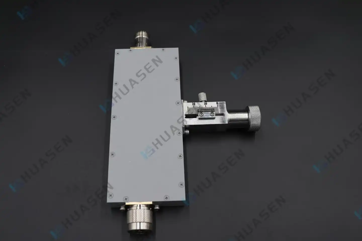
Understanding Coaxial Variable Attenuators
Core Operating Principles
The resistance network inside each coaxial variable attenuator soaks up RF energy in a way that changes based on the setting on the dial. There is only one loss number that can be changed for fixed attenuators. Different types, on the other hand, have ways to change the resistance path mechanically, like spiral drives, turret switches, or micrometer screws. The internal resistance cards move when an engineer turns the control knob. This changes how the signal is received while keeping the 50-ohm impedance the same. This matching of impedance stops reflections that would change waveforms and make measurements less accurate if they didn't happen.
Key Performance Parameters
Getting the basic specs of a device helps the buying team decide if it's right for the job. It is the smallest amount of signal loss that can happen when the attenuator is set to 0 decibels. It is generally between 0.3 and 1.5 decibels, but this changes with the frequency. Many times, the range of dB cuts is between 0 and 30 dB, 0 and 60 dB, or 0 to 100 dB. Based on the frequency range, you can figure out the working bandwidth. Many types of broadband routers can work from DC to 18 GHz, and some are even able to reach millimeter-wave bands. VSWR stands for voltage standing wave ratio. It shows how well the resistance fits. Most of the time, values below 1.40:1 are good for radar use.
| Parameter | Specification | Impact on System Performance |
|---|---|---|
| Frequency Range | DC-18 GHz | Broader coverage reduces component count in multi-band systems |
| Attenuation Range | 0-30 dB | Adequate for receiver protection and gain leveling |
| Accuracy | ±1.0 dB | Maintains calibration integrity across test cycles |
| VSWR | < 1.30:1 | Minimizes signal reflections and measurement uncertainty |
| Power Handling | 2W Average | Suitable for signal-level testing; verify for transmitter-side use |
Attenuator Types and Frequency Models
The market is mostly made up of three main types. Continuously variable types have rotating gears that give them an endless range of precision. This makes them perfect for measuring and tuning analog circuits and for use in the lab. Step attenuators let you change the loss in clear steps of 1 dB, 5 dB, or 10 dB, which makes them better for automated test equipment that needs to be able to repeat results. Electronically controlled models have PIN diodes or MEMS switches built in, which let you change them from a distance using DC control voltages.
Above 10 GHz, frequency-specific design issues become very important. At millimeter-wave frequencies, parasitic capacitance in the resistance elements makes them less accurate, so they need to be built with special thin-film materials and have precise connection contacts like 2.92 mm or 2.4 mm types. When looking at datasheets, make sure you look at the flatness specification, which is given as ±0.5 dB to ±2.0 dB across the stated bandwidth, to make sure the device stays accurate throughout your operational spectrum.
Applications of Coaxial Variable Attenuators in Radar and ECM Systems
Radar Signal Conditioning
For modern phased array radar systems to work, the amplitude needs to be precisely controlled across hundreds of antenna elements. Engineers add coaxial variable attenuators to each signal path during beamforming calibration to make up for differences in the parts and cable losses. This makes sure that the array opening is excited evenly, which directly improves beam pattern symmetry and side-lobe suppression. Attenuators simulate target echo strengths during receiver testing by adding controlled loss between the transmitter and receiver chains. This checks the accuracy of automatic gain control algorithms without having to deploy them in the field.
ECM Power Management
Coaxial variable attenuators change the strength of blocking signals in real time, which is important for electronic warfare systems. When threat radars change the frequencies or levels of power they use, ECM systems have to change the countermeasure emissions they send out in response. By putting a buffer in front of the power amplifier stage, operators can lower the output power without having to retune the amplifier bias network, which would add delays that aren't good for situations where an electronic attack needs to happen quickly. Military-grade attenuators are fully protected, so they work reliably even when they are exposed to pressure, changes in temperature, and water while they are in the air or on a ship.
Device Protection and Dynamic Range Optimization
Sensitive spectrum analyzers and vector network analyzers set maximum input power thresholds, which are usually between +10 dBm and +30 dBm. If these thresholds are exceeded, the internal mixers become damaged. Engineers put a coaxial variable attenuator at the input port of the measurement instrument to characterize high-power radar parts. This setup lets you safely look at signals stronger than 50 dBm while keeping the accuracy of your measurements. Being able to change the attenuation without disconnecting the cables makes test procedures easier during production qualification testing and protects precision connectors from damage.
The benefits go beyond just safety. Technicians make the best use of the dynamic range by controlling signal intensity at intermediate test points. This keeps signals well above the noise floor and stops compression in later gain steps. In multi-stage receiver chains, where cascaded gain can quickly drive signals into saturation, this is a must.
How to Choose the Right Coaxial Variable Attenuator for Your Radar or ECM Project?
Technical Selection Criteria
Setting working settings is the first step in matching device specs to application needs. Next is frequency band alignment. Make sure that the attenuator's range covers your radar's entire working spectrum, including any frequency agility or bandwidth-hopping features. The expected signal dynamic range determines the attenuation range. For example, radar tuning needs 30 to 40 dB of adjustments, while ECM tests may need 60 dB or more to model different danger scenarios.
Power handling needs to be looked at very carefully. Average power rates show the maximum power that can be used continuously, but radar systems produce a lot of power when they send pulses. For pulse widths less than 1 microsecond, check the device's peak power specs and use the right derating. If you don't pay attention to this parameter, the resistive element will burn out and the calibration will shift permanently.
| Application Type | Recommended Attenuation Range | Typical Power Requirement | Key Connector Type |
|---|---|---|---|
| Radar Receiver Testing | 0-40 dB | 2W Average | SMA, N-Type |
| ECM Signal Leveling | 0-60 dB | 5W Average, 500W Peak | N-Type, 7/16 DIN |
| Lab Calibration | 0-100 dB | 1W Average | SMA, 3.5mm |
| Phased Array Beamforming | 0-30 dB | 10W Average | 2.92mm, SMP |
Evaluating Manufacturers and Supply Chain Factors
Big names like Keysight Technologies, Pasternack Enterprises, and Mini-Circuits all sell a lot of goods that have good data stored on them. If you want to compare service companies, you should ask for specifics like MTBF numbers and temperature stability factors. It has been approved by MIL-DTL-3933, which means it meets standards for being immune to shock, shaking, and dampness. For security purposes, these are very important.
When buying coaxial attenuators, there are more things to think about than just the unit price. Customized frequency bands or connector configurations can take up to 12 weeks to make, especially if orders need calibration certificates that can be tracked back to national standards. There are a lot of different minimum order quantities. Catalogue items may only ship one unit, but custom designs usually need at least 10 pieces to cover the cost of the tools. Talk to the supplier about their pricing structures so that they can support multi-year programs with stable component availability. These should include prototype quantities and ways to move up to volume production.
How quickly technical help responds has a huge impact on project timelines. Check to see if the manufacturer offers S-parameter files for simulation, sample evaluation programs, and an application engineering staff that can help with integration issues. As part of long-term defense projects, after-sales service should include recalibration services, fixed response promises, and control of waste.
Performance Optimization and Best Practices for Deploying Coaxial Variable Attenuators
Integration and Installation Guidelines
To get a good fit, you must first take care of the connectors. Before you put the pieces together, make sure there is no damage to the threads and use isopropyl alcohol to clean the contacts. Do not overtighten, as this can damage the impedance match. Instead, use a torque wrench that has been calibrated and set to the manufacturer's instructions. Most of the time, this is 8 inch-pounds for SMA connectors and 12 inch-pounds for N-Type connections. It is best to put the regulator somewhere easy to reach during tests so that it can be changed. But don't put it near things that will shake a lot because that could change the settings on the dial.
When moving wires around the attenuator, it's important to be careful not to move the joints too much. If the attenuator is placed in a rack, it is better to have the body of the attenuator hold it up instead of letting the coaxial lines do it. Add more than one attenuator to an automatic test system. Make sure that each one has a label with the date it was calibrated and a serial number so that it can be found when checks are being done.
Calibration and Maintenance Protocols
Set adjustment times based on how often the device is used and how much it is exposed to the surroundings. Laboratory instruments that are kept in a controlled environment usually need to be checked once a year, while units that are used in harsh environments should be checked every six months. During testing, workers move the attenuator through all of its frequency ranges and compare the real loss values to the ones that were specified. If the deviation is more than ±1.5 dB, it needs to be fixed or replaced.
Part of regular maintenance is checking the adjustment mechanism visually for signs of wear, like knobs that don't fit together properly or that won't turn. Use lint-free wipes to clean the outside of the device; stay away from agents that could get inside the seals and damage the internal resistance elements. Keep empty coaxial variable attenuators in a place with connection caps on them to keep dust out and avoid damage to the parts.
Emerging Technology Trends
Digital control interfaces are changing how coaxial variable attenuators are used. Modern models that are controlled electronically can work with common communication protocols like USB, Ethernet, or RS-232. This lets software-defined radio architectures change the attenuation in microseconds. This feature is very useful in adaptive radar systems that change waveforms based on threats they detect.
5G infrastructure and unmanned aerial vehicle (UAV) platforms are pushing for miniaturization, which needs small form factors that don't sacrifice performance. Surface-mount variable attenuators and coaxial attenuators can now fit on surfaces that are less than 5 mm x 5 mm and still work up to 40 GHz. As more self-driving cars and satellite communications use millimeter-wave radar systems, high-frequency attenuation technology is likely to keep getting better.
Conclusion
Selecting and deploying coaxial variable Attenuators in radar and ECM systems requires balancing technical performance against procurement realities. Understanding core parameters—frequency range, attenuation accuracy, power handling, and VSWR—enables confident device specification. Practical considerations such as connector compatibility, calibration intervals, and supply chain stability determine long-term project success. As RF systems evolve toward higher frequencies and adaptive architectures, variable attenuators will remain indispensable tools for signal conditioning, system protection, and performance verification across defense, aerospace, and telecommunications sectors.
FAQ
1. What distinguishes continuously variable attenuators from step attenuators in ECM applications?
Continuous variable models offer infinite resolution, allowing precise matching to specific signal levels during manual tuning procedures. Step attenuators provide discrete, repeatable loss values ideal for automated testing where programmable control and numeric precision outweigh the need for fine adjustment. ECM systems favor step models when interfacing with digital control systems, while laboratory radar calibration benefits from continuous adjustment.
2. How do I determine the appropriate attenuation range for my radar test setup?
Calculate the difference between your maximum source power and the receiver's safe input limit, then add 10-15 dB margin for operational flexibility. Radar systems with 40 dBm transmitters feeding receivers rated for +10 dBm input require at least 30 dB attenuation; selecting a 0-40 dB model provides headroom for measurement variations and aging component drift.
3. Which manufacturers deliver reliable performance for defense radar programs?
Keysight Technologies and Pasternack Enterprises consistently meet MIL-STD requirements with documented shock and vibration test results. Mini-Circuits offers cost-effective solutions for commercial radar applications with rapid delivery schedules. Verify that chosen suppliers maintain ISO 9001 certification and provide calibration data traceable to NIST standards, essential for contract compliance.
Partner with Huasen Microwave for Your Precision Attenuation Needs
Huasen Microwave Technology brings three decades of RF component expertise to defense and telecommunications markets worldwide. Our Coaxial Variable Attenuator (CVA) covers DC-18 GHz with helical fine-tuning precision across a 0-30 dB range, housed in a compact, fully sealed enclosure that withstands harsh operational environments. As a trusted coaxial variable attenuator manufacturer, we combine high-precision performance with responsive engineering support—from initial specification consultation through calibration data delivery.
Engineers and procurement specialists gain access to customized frequency configurations, expedited sampling programs, and volume pricing structures designed for multi-year defense contracts. Our sales team at sales@huasenmicrowave.com provides detailed S-parameter models, integration guidance, and after-sales recalibration services that reduce the total cost of ownership. Discover how Huasen Microwave's proven track record in radar and ECM components can accelerate your next project—contact us today for technical datasheets and quotation assistance.
References
1. Pozar, David M. Microwave Engineering, 4th Edition. Hoboken: John Wiley & Sons, 2012.
2. Skolnik, Merrill I. Introduction to Radar Systems, 3rd Edition. New York: McGraw-Hill Education, 2001.
3. Adamy, David L. EW 102: A Second Course in Electronic Warfare. Norwood: Artech House, 2004.
4. Hiebel, Michael. Fundamentals of Vector Network Analysis. Munich: Rohde & Schwarz, 2008.
5. Agilent Technologies. Application Note 1287-1: Understanding the Fundamental Principles of Vector Network Analysis. Santa Clara: Agilent Technologies, 2000.
6. IEEE Standard 291-1991. IEEE Standard Methods for Measuring Electromagnetic Field Strength of Sinusoidal Continuous Waves, 30 Hz to 30 GHz. New York: Institute of Electrical and Electronics Engineers, 1991.
Send Inquiry