Yagi Antenna Applications in Wireless Communication Systems






2026-07-17 16:00:46
That's because Yagi antennas send signals only to certain areas; wireless systems would not be able to work without them. Tests with radio waves, following satellites, point-to-point lines, and cellular backup all need these. They can send signals over long distances with little damage because their beamwidth is narrow and their gain is high. This will improve the 5G system, messaging at sea, and the use of sensors. To make their networks more open, businesses need safe, low-cost ways to do it. When you need better front-to-back ratio performance and focused energy distribution, these directed antennas are a must.
Understanding Yagi Antenna Fundamentals
Design, Architecture, and Operating Principles
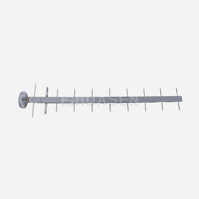
The Yagi-Uda array uses parasitic element interaction to do its job. Electromagnetic energy is sent out by an active element. The pattern of that energy is changed by passive directors and mirrors. This setup creates positive interference in the forward direction. The gains range from 6 dBi to 18 dBi, depending on the length and number of parts in the boom. Putting the reflector behind the driven element changes the radiation to face backwards. In well-designed systems, this can increase the front-to-back ratio by more than 18 dB.
The ones used today are made of 6063-T5 aluminum metal, which is used in aircraft, and have anodization layers that are more than 12 microns thick. Because of this, they won't rust in marine or industrial settings. The space between elements is based on exact quarter-wavelength predictions, and mistakes are kept to within ±0.5mm during production to make sure the electrical performance stays stable over the whole working range.
Key Performance Metrics
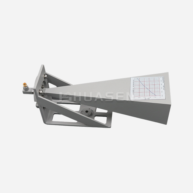
Antenna gain is the most important factor. It shows how much a signal is amplified compared to an isotropic radiator. The Tri-band SGABM model in our Standard Gain Yagi (YAG) line works well across all frequency bands. It has a set gain of 5.3 dB and a 10% bandwidth, making it great for VHF/UHF measurement jobs between 30 MHz and 3000 MHz.
As long as the Voltage Standing Wave Ratio (VSWR) is less than 1.5:1, power is transferred well and not much energy is lost. How big the coverage area is depends on how wide the half-power beam is. For long-distance links, narrower beams focus energy, while wider patterns light up more space. Cross-polarization discrimination can be more than 20 dB in good implementations, and signal compatibility is affected by polarization purity.
Material Properties and Environmental Durability
The hard conditions of operation are met by building at an industrial level. The boom sections are strong enough to handle wind speeds of up to 200 km/h thanks to mounting frames made of passivated SUS304 stainless steel. Instead of set screws, compression bolts are used to connect parts to booms. This gets rid of the paths for galvanic corrosion that break the continuity of electricity.
Connector systems have sealed feed boxes with weep holes to let water drain. This keeps their IP65 ratings for protection against entry. The fact that it is stable from -40°C to +70°C means that it can be used for both cold weather sets and hot operations. People can live in a coastal area for at least 500 hours, according to ASTM B117 tests for salt spray. This is important for maritime communication systems and offshore platform installations.
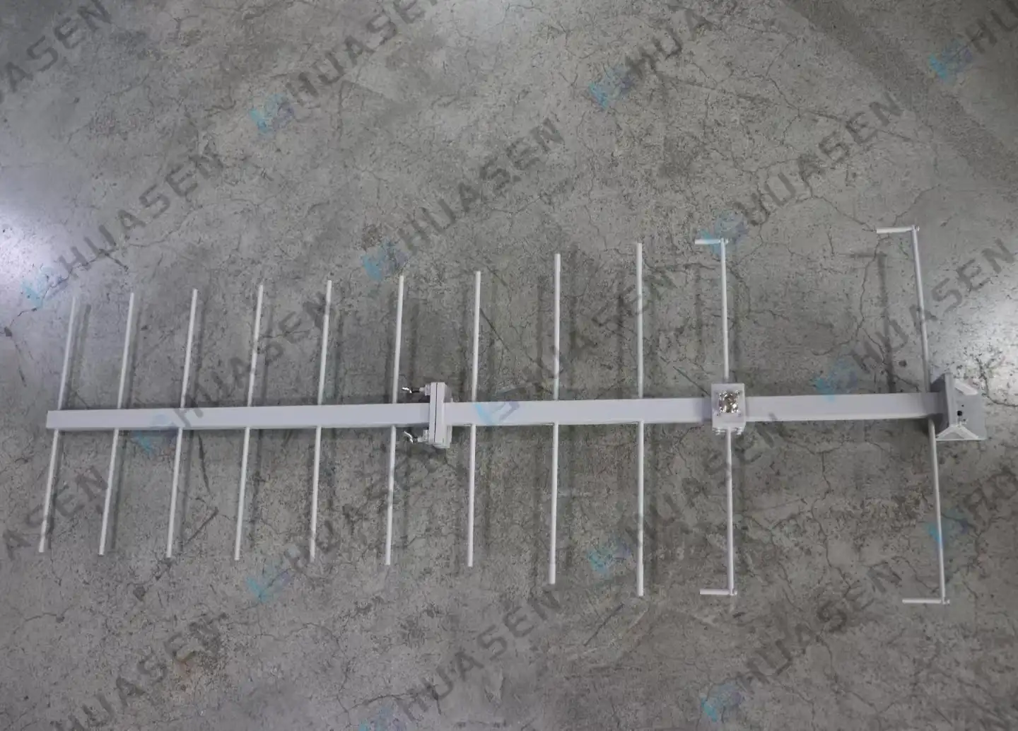
Yagi Antenna Applications in Wireless Communication
Cellular Infrastructure and Backhaul Networks
Building blocks for smartphones and backup networks
For 5G backup lines, mobile network providers use directed arrays to connect fiber points of presence to cell sites that are far away. The frequency range for these links is between 2.5 GHz and 3.7 GHz. As long as there is a clear line of sight, the narrow beamwidth keeps sectors next to it from interfering, but it still has a range of 20 km or more. With our dual-polarized Yagi antenna (DCP+DA), you can use orthogonal polarization routes for 2x2 MIMO operation. This doubles spectral efficiency without having to add more frequency.
The beam features that can be changed are useful for base station fronthaul. Coverage designs between 35° and 110° and 60° and 35° can be used to fit different site plans. Modular construction lets field techs finish setups in 15 minutes using standard mounting hardware. This saves money on truck rolls and speeds up plans for network densification.
| Application Sector | Frequency Range | Typical Gain | Link Distance | Key Advantage |
|---|---|---|---|---|
| 5G Backhaul | 2.5-3.7 GHz | 10-12 dBi | 15-25 km | MIMO capability |
| VHF Marine Communications | 156-162 MHz | 6-9 dBi | 30-50 km | Salt fog resistance |
| UHF Telemetry | 400-470 MHz | 8-11 dBi | 20-40 km | Low wind load |
| Satellite Ground Stations | 1.5-2.7 GHz | 12-15 dBi | N/A | Circular polarization |
Satellite Communication and Tracking Systems
For messages to stay strong when the satellites drop in low Earth orbit (LEO), base stations must be able to handle circular polarisation. Engineers used phase two crossed Yagi antenna arrays to create RHCP or LHCP with axial ratios lower than 3 dB. The signal stays locked during satellite passes with this setup, which would lead to 20+ dB nulls in linear polarisation.
VSAT stations for ships use Yagi antenna arrays that are manually guided on stable bases to keep track of geostationary satellites and take into account the ship's pitch and roll. Whole systems usually weigh less than 8 kg. This makes the inertial loads on steering motors lower. This makes them last longer and use less power than bigger parabolic mirrors.
Point-to-Point Wireless Bridging
For SCADA data and video security backhaul, industrial sites use ISM band (902–928 MHz, 2.4–2.5 GHz, and 5.725–5.850 GHz) links that don't need licenses. Yagi antennas give you the directionality you need to run multiple links in small areas without interfering with each other. With 20 dBm transmit power and a pair of 14 dBi antennas, a 10 Mbps Ethernet connection is reliable over 8 km, meeting the requirements for Fresnel zone clearance with the shortest possible tower height.
For smart grid Advanced Metering Infrastructure (AMI) networks, utility companies use UHF bands. The high front-to-back ratio blocks out RF noise from cities, keeping the system up 99.99% of the time in places near substations and switching yards that are electrically hostile. Implementations of polarisation diversity swap between vertical and horizontal parts based on real-time measures of signal strength. This keeps the link open during rain or snow.
RF Testing and Calibration Laboratories
Facilities that do measurements need reference antennas that have gain accuracy that can be tracked back to national standards. Our Tri-band SGABM line keeps a gain range of ±0.5 dB across VHF and UHF bands, which lets EMC test antennas and spectrum analysers be calibrated. The fixed-gain feature gets rid of the need for tuning, which lowers measurement uncertainty budgets.
Yagi antennas are used as light sources on antenna test ranges to measure patterns and describe radomes. The clean radiation pattern with sidelobes below -18 dB reduces range reflections so that devices being tested can be accurately evaluated. Precision rotators can be mounted with positioning accuracy better than 0.1°, and automated pattern acquisition protocols that meet IEEE 149-2021 standards can be used.
Comparing Yagi Antennas with Other Antenna Types
Yagi versus Omnidirectional Antennas
Yagi antennas vs. omnidirectional antennas
Omnidirectional designs send out the same amount of radiation in all horizontal directions, making them good for mobile uses where the emitter location changes. While a 2.15 dBi omnidirectional antenna spreads energy across the whole azimuth, a 10 dBi Yagi antenna focuses the same amount of power into a 50° sector; their coverage of 360° makes the power less useful. This 7.85 dB edge in directivity means that the range is 6 times farther or the coverage area is 36 times bigger in point-to-point situations.
Omnidirectional antennas are chosen by system designers for base station uses that serve mobile clients coming from all directions. On the other hand, Yagi antenna directionality is good for backup lines, fixed wireless access, and satellite ports. The decision is based on whether the application needs a specific point-to-point connection or spread coverage.
Yagi versus Parabolic Reflector Antennas
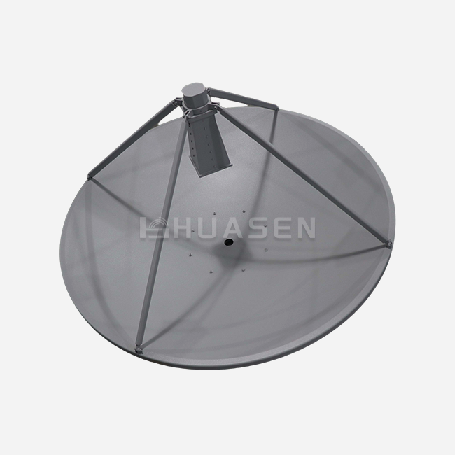
Because their openings are bigger, parabolic dishes get better gains (24 dBi to 30+ dBi), which is why they are best for microwave backhaul above 6 GHz. However, their wind load grows exponentially with diameter; a 0.6-metre dish has a frontal area of 0.28 m², while a Yagi antenna with the same gain has a frontal area of 0.08 m² at lower frequencies. Because of the need for stronger foundations and larger tower designs, installation costs go up.
Below 3 GHz, Yagi antennas work just as well as other types, but they can handle wind better and cost less to place. The modular element design makes it easier to carry and put together in the field. For example, a 12 dBi UHF Yagi antenna can be broken down into parts that are less than 2 metres long, making them small enough to fit in most vehicle trunks. This advantage in terms of logistics makes it possible for rapid deployment in situations like disaster recovery and short-term event communications.
Selection Criteria for Optimal Performance
There are three main things that affect the choice of antenna yagi: the operating frequency, the required gain, and the mechanical limitations. Higher frequencies let shorter element lengths work. For example, the boom length of a 2.4 GHz Yagi antenna is only 80 cm, while the boom length of a 450 MHz equivalent is 4 metres. Gain requirements combine the need for a link budget with the limitations of the beamwidth. Too much gain makes the beam narrower, which makes alignment harder and makes it more sensitive to structure sway.
| Parameter | Standard Gain YAG | Tri-band SGABM | Dual-Polarized DCP+DA |
|---|---|---|---|
| Frequency Range | Single band (custom) | VHF/UHF (tri-band) | 200-2500 MHz (expandable to 30-5800 MHz) |
| Gain | 6-18 dBi | 5.3 dBi fixed | 3-12 dBi |
| Polarization | Linear (H or V) | Linear (V) | Dual (H/V or ±45°) |
| VSWR | <1.5:1 | <1.5:1 | <1.5:1 |
| Isolation (port-to-port) | N/A | N/A | >25 dB |
| Installation Time | 20-30 min | 20 min | <15 min (modular) |
| Wind Survival | 160 km/h | 180 km/h | 200 km/h |
| Weight | 3-12 kg | 4.5 kg | 5-8 kg |
Material choice is affected by environmental factors. For coastal missions, marine-grade anodisation and steel parts are needed to protect against rust from salt spray. Low-temperature gasket materials that stay flexible below -40°C are needed for installations in the Arctic. High-albedo coats help desert settings by absorbing solar energy and stopping heat expansion that changes the space between elements.
Procurement Guide for Yagi Antennas
Supplier Evaluation and Qualification
To find qualified manufacturers, you have to look at a lot of different competency dimensions. Production capacity determines the ability to fulfil a large order. Make sure that the annual output is three times the order quantity to account for changes in demand. For example, ISO 9001:2015 certification means that quality management systems are written down, and ISO 14001 certification means that environmental rules related to RoHS and REACH laws are followed.
Ask for test reports that show measurements of VSWR, gain, and pattern taken in certified anechoic chambers. Reliable suppliers give out calibration certificates that can be traced back to national metrology institutes like NIST, NPL, and PTB. These certificates also include statements about measurement uncertainty. Testing for Passive Intermodulation (PIM) below -150 dBc shows that it can be used in cellular base stations where noise from transmitters shouldn't make receivers less sensitive.
Customisation Capabilities and Lead Times
Off-the-shelf goods don't always perfectly meet the needs of a specific system. Check out the engineering support for changing the frequency band, impedance matching networks, and different connector options. Our design team changes the DCP+DA series from 30 MHz to 5.8 GHz and delivers prototypes every 8 weeks to support iterative development processes.
Custom mounting frames for non-standard tower connections, radome cases for better aesthetic integration, and built-in amps for better receiver sensitivity are some of the mechanical changes that can be made. Talk about the minimum order quantities for custom variants. For cost-effective tooling amortisation, these are usually between 50 and 100 units. In buy deals, include clear acceptance criteria. For example, IEC 60835 for EMC test antennas is a measurement standard that should be used.
Total Cost of Ownership Analysis
The buying price is only 30–40% of the total cost over the life of the item. When you count the time it takes to install our modular designs, the time it takes in the field goes from 45 minutes to less than 15 minutes, which saves $120-$200 per site in technician costs. It depends on how harsh the environment is; installations near the coast need to be inspected every year, while installations in mild climates only need to be inspected every three years.
Manufacturers' confidence in the antennayagi is shown by their warranty terms. For example, we offer 3-year coverage that includes replacement units and return shipping, which eliminates the risk of downtime. Long-term support depends on having spare parts available; check component ageing management practices before committing to platforms. Most of the time, volume discounts start at 25 units, which saves you 5–8%, and get even better after 100 units, which saves you 12–18%.
Conclusion
Directional antenna technology continues proving essential across telecommunications infrastructure, aerospace systems, and industrial IoT networks. The Yagi-Uda configuration delivers unmatched cost-performance ratios for applications requiring focused signal propagation between 30 MHz and 6 GHz. Dual-polarisation variants enable MIMO throughput doubling, while modular construction facilitates rapid deployment in challenging environments. Procurement success depends on matching electrical specifications to link budget requirements, validating environmental durability through certified testing, and partnering with manufacturers offering comprehensive customisation support. As wireless communication systems evolve toward higher frequencies and smarter architectures, these fundamental design principles adapt through advanced materials and integrated electronics, ensuring continued relevance across emerging applications.
FAQ
1. What frequency range works best for long-distance links?
Lower frequencies between 400 and 960 MHz propagate farther with less atmospheric attenuation, making them ideal for 30+ km rural connectivity. However, antenna size increases—a 450 MHz Yagi antenna spans 4 metres versus 0.8 metres at 2.4 GHz. Balance range requirements against practical installation constraints when selecting operating bands.
2. How does weather affect Yagi antenna performance?
Rain fade primarily impacts frequencies above 10 GHz; UHF and lower bands experience negligible precipitation loss. Ice accumulation detunes element spacing by altering effective electrical length—marine-grade radomes prevent build-up. Wind-induced tower sway causes pointing errors; ensure mechanical installations maintain alignment within half the beamwidth under maximum rated wind loads.
3. Can I use a single Yagi antenna for transmit and receive?
Yes, when both functions operate on the same frequency with adequate transmit-receive isolation via a diplexer or circulator. Simultaneous transmission and reception on different frequencies requires diplexed feed networks with proper filtering to prevent transmitter noise from desensitising the receiver. Consult RF engineers to design appropriate coupling networks for your specific frequency plan.
Partner with Huasen Microwave for Superior Directional Antenna Solutions
Huasen Microwave Technology brings three decades of RF engineering excellence to every Yagi antenna we manufacture. Our product line spans Standard Gain YAG models for dedicated frequency applications, Tri-band SGABM calibration references for metrology labs, and modular Dual-Polarized DCP+DA systems that can be deployed in under 15 minutes. We customize frequency coverage from 30 MHz to 5.8 GHz, matching your exact system requirements with documented performance validated in our ISO 17025-accredited test facility. Volume pricing supports large infrastructure projects, while responsive technical support ensures successful integration. Connect with our applications engineering team at sales@huasenmicrowave.com to discuss your wireless communication challenges. As a trusted Yagi antenna manufacturer, we deliver the reliability and performance your critical systems demand.
References
1. Balanis, Constantine A. Antenna Theory: Analysis and Design. 4th ed. Hoboken: John Wiley & Sons, 2016.
2. Kraus, John D., and Ronald J. Marhefka. Antennas: For All Applications. 3rd ed. New York: McGraw-Hill Education, 2002.
3. IEEE Standard for Definitions of Terms for Antennas. IEEE Std 145-2013. New York: Institute of Electrical and Electronics Engineers, 2014.
4. Milligan, Thomas A. Modern Antenna Design. 2nd ed. Hoboken: John Wiley & Sons, 2005.
5. Stutzman, Warren L., and Gary A. Thiele. Antenna Theory and Design. 3rd ed. Hoboken: John Wiley & Sons, 2012.
6. Volakis, John L., ed. Antenna Engineering Handbook. 4th ed. New York: McGraw-Hill Education, 2007.
Send Inquiry