When to Use a Waveguide Transition in RF System Design?






2026-07-14 16:57:47
When your RF system needs to transfer energy between various transmission line shapes while maintaining signal integrity, waveguide transition components become crucial. When you connect waveguides of different sizes or bridge between coaxial plugs and waveguide flanges, these passive devices fix impedance problems. They should be used whenever your design has to deal with sudden changes in the transmission medium. This is especially important for high-frequency uses above the X-band, where coaxial lines lose too much signal. Knowing when these parts are most useful helps buying teams avoid system failures that cost a lot of money and ensures that radar, satellite uplinks, and telecommunications equipment work reliably.
Understanding Waveguide Transitions: Fundamentals and Applications
What Defines a Quality Waveguide Transition?
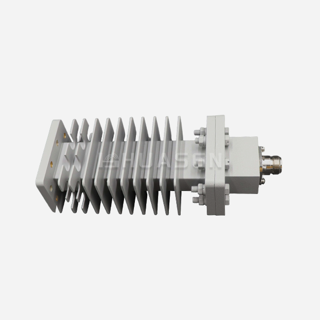
Modern changes work as precisely designed impedance transformers that make the source's and load's characteristic impedance match. Based on Chebyshev matching rules, the internal structure uses either curved shapes or stepped sections. With stepped setups, matching is possible in short physical lengths by using quarter-wave transformer sections, while tapered designs offer a wider bandwidth through slow changes in size. The goal of both methods is the same: to reduce the voltage standing wave ratio (VSWR) as much as possible to stop harmful power echoes.
Core Application Domains
Satellite ground stations are one of the main places where high-power amplifiers with big WR-137 flanges need to connect to antenna feeds that need WR-112 inputs. This change in size keeps the signal strong all the way through the communication chain, from the shelter equipment to the antenna hub. Defense radar systems use complicated twist-and-taper patterns to send data between transmitters and gimballed antennas, even when the airframe geometry is limited. This keeps the systems working even when there is a lot of shaking, as required by MIL-STD-810.
For vector network analyzer testing setups in laboratories, metrology-grade coax-to-waveguide transitions are required. These precision fittings make it possible to test components accurately while keeping error budgets within the limits set by ISO 17025 compliance. Standard industrial grades don't meet the mechanical accuracy needed here; flange flatness limits are usually kept within ±0.02 mm.
Signal Integrity Through Mode Purity
If the waveguide transitions are properly designed, they stop the activation of parasitic higher-order modes that hurt the performance of the system. When changing from a rectangular waveguide cross-section to a circular one, the design needs to stop any TE10-to-TM11 mode changes that aren't needed. This mode purity protection is very important in situations where the signal-to-noise ratio has a direct effect on how well the system works, like in electronic warfare receivers or deep-space communication lines.
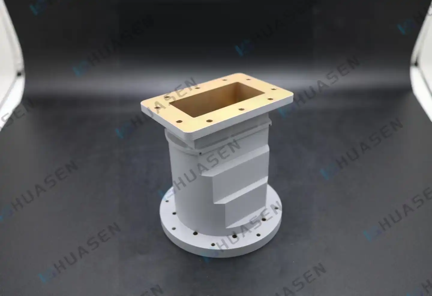
When to Choose Waveguide Transitions Over Other Interconnection Methods?
Performance Comparison with Traditional Approaches
Because they are flexible and easy to place, coaxial wires are most often used in low-frequency installations. But above 18 GHz, their dielectric losses go up a lot, which means they can't be used for Ka-band or millimeter-wave uses. Microstrip transmission lines can fit into small spaces on circuit boards, but they can't handle power levels of kilowatts or more without melting. Air-dielectric Waveguide Transitions get rid of both problems at the same time.
Metal waveguide design is better at getting rid of heat, so it can be used continuously at power levels that would melt coaxial center wires. In satellite transfer chains that send hundreds of watts, this temperature management feature keeps parts from breaking down over the course of several years of use. Since there are no dielectric materials, there are also no worries about breakdowns that can happen with coaxial connections when they are under a lot of power stress.
Application-Specific Selection Criteria
The frequency range of your product is the first choice filter. Below 6 GHz, cable systems are usually more cost-effective unless they can handle more than 100 watts of power all the time. Between 6 and 40 GHz, waveguide transitions can be used in fixed systems because they have better insertion loss characteristics, which makes up for their higher starting costs. Above 40 GHz, waveguide connections are the only option because coaxial ones lose too much signal.
Different businesses are affected by space limits in different ways. To stay within strict weight limits, airborne platforms need aluminum changes that are light and have the smallest possible size. Ground-based telecoms infrastructure can support heavy copper or brass construction, which makes it better at conducting electricity. For maritime radar systems, designs need to be tough and resistant to rust. This is usually done through special plating methods that are checked by salt spray testing that meets ASTM B117 standards.
Real-World Problem Solving
When updating 5G backhaul links, a big phone company found that using coaxial jumpers between base station amplifiers and antenna arrays caused too much signal loss. When they switched to precise waveguide transitions, insertion loss went down by 0.4 dB per connection point. This meant that their link budget margins got better across their whole network operation. The mechanical safety of the transitions got rid of the sporadic faults that the original coaxial assemblies had because of stresses caused by thermal expansion.
Key Design Principles and Performance Considerations
Impedance Matching Fundamentals
To get a low VSWR, you need to pay close attention to how the input and output openings change shape. The length of the transition is directly related to how well it handles bandwidth. Longer tapers can handle wider frequency ranges, but they take up more mounting room. Chebyshev polynomial theory is used to spread reflections across the working band so that they interfere negatively at the output port. Multi-section stepped designs are a good middle ground.
Through skin effect events, the quality of the surface finish has a big effect on entry loss. At microwave frequencies, most of the current flows through the thinnest layers of the conductor. When the internal surface roughness is more than 63 micro-inches, the effective resistance goes up. This turns the signal energy into heat. Premium changes require silver or gold finishing according to MIL-G-45204 standards to stop copper oxidation, which would weaken transmission over time.
Thermal and Power Management
The air breakdown voltage inside the waveguide cavity is the main factor that determines the peak power handling. When the design is done right, the electric field stays below the ionization level for the whole working bandwidth. When it comes to thermal discharge efficiency, average power capacity is related. Aluminum housings are better at spreading heat than stainless steel ones, even though aluminum doesn't conduct electricity as well. For uses with more than 1 kilowatt of average power, fixing clamps that are cooled by forced air or liquid may be needed.
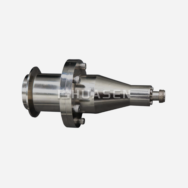
Multipaction is a failure mode that only happens in vacuums, where electrons bounce off of surfaces that are opposite to each other when RF is applied. Space-based systems that use waveguide transitions, including circular waveguide transitions, need to go through a multipaction risk analysis that uses computerized electromagnetic modeling and test chamber data to make sure the model is correct. When needed by mission plans, surface treatments and changes to the shape can stop this effect.
Integration Best Practices
As few links as possible should be made between the transmitter output and the radiating part in antenna feed networks. At each joint, there are possible reflection points that add up and cause the VSWR to decrease. Choosing transitions with return loss higher than 25 dB (VSWR <1.10:1) helps keep system performance within link budget limits.
Standardizing mechanical interfaces makes managing the supply chain easier and makes inventory less complicated. UG-series flanges are used for frequency bands up to the Ku-band, CPR flanges are used for business satellite uses, and UBR interfaces are used for defense radar systems. Instead of depending only on dimensional models to make sure that products from different sellers can be used interchangeably, procurement requirements should directly refer to these standards.
Procurement Guide: How to Source and Order Waveguide Transitions?
Evaluating Supplier Credentials
Manufacturers you can trust show uniform quality by showing that they follow industry standards. For proof of organized quality control, look for ISO 9001 recognition. Defense companies should use DPAS ratings or similar authorization to ensure MIL-STD conformance. You can directly check the electrical performance before committing to large orders by asking for sample S-parameter test data from previous production lots.
When evaluating a company's ability to make things, they should look at its precise machining tools and inspection procedures. Using a coordinate measuring machine (CMM) to check the smoothness of the flange and the size of the opening stops expensive field failures caused by RF leaks. Every vector network analyzer unit needs to be tested regularly across the full frequency range, not just statistically. This is especially important for aircraft and defense uses, where field repair costs are too high.
Custom Versus Standard Product Decisions
Standard catalogue items have shorter wait times and lower unit costs for frequency bands and flange pairs that are used most often. In exchange, you might have to deal with mechanical boxes or data that are too big for your needs and that you pay for but don't use. Custom designs make sure that the size, weight, and electricity performance are just right for the purpose, which makes the engineering investment worthwhile for production runs of more than 50 units per year.
Based on how your system is set up, Huasen Microwave's technical team can help you make this choice. Our many years of experience since 1993 help us figure out when standard WR-series transitions are enough and when custom tapers or specialized plating is worth the extra money. This meeting often shows ways to cut costs through standardization that weren't obvious to buying teams that were only looking at what was asked for.
Lead Time and Logistics Planning
Standard waveguide transitions usually ship two to four weeks after an order is placed, so they can be used to make prototypes and fix things quickly. For custom designs, engineering approval and first-item inspection take 6 to 12 weeks. For large orders, production runs take another 4 to 6 weeks. By including these dates in project schedules, delays on the key path during the system integration steps can be avoided.
When you buy more than 100 pieces a year, you can save 15 to 30 percent on each item through bulk buying deals. Setting up blanket purchase orders with planned releases lets you get good prices and keep enough supplies to meet changing project needs. International exports are better off with consolidated freight plans because they make it easier to clear customs and lower the cost of logistics per unit. This is especially true for bigger waveguide systems (circular waveguide transition) whose dimensional weight has a big effect on carrier charges.
Conclusion
Waveguide transitions give you measured performance benefits when your RF system design needs to connect signals with low loss between transmission lines with different shapes. The choice to use these parts depends on the working frequency, power levels, and environmental conditions that are too strong for coaxial wire. To make the right choice, you need to balance electrical needs with mechanical limitations, and you also need to make sure that the quality standards of the provider meet your long-term, reliable needs. When your company buys things, it's best to think about both standard products and special building options. This way, your company can get the best system performance while keeping overall costs down throughout the supply chain.
FAQ
1. What distinguishes tapered from stepped transition designs?
Tapered transitions change the cross-sectional dimensions slowly through linear or exponential curves. This lets them work over a wider range of frequencies with lower reflection coefficients. To keep the VSWR low across the working band, you have to deal with longer physical lengths. Stepped transitions use quarter-wave transformer sections to match resistance in small mechanical packages, but with a slightly smaller bandwidth than tapered designs that offer the same level of performance. The best way to do something depends on how much room you have and what frequencies you need to cover.
2. How does surface plating affect long-term reliability?
At microwave frequencies, the skin effect makes the RF current flow focus in the top layers of conductors. Silver and gold finishing stops copper from oxidizing, which raises the surface resistance over time. This keeps the insertion loss standards even after more than 20 years of use. These protective coats work well in maritime and tropical settings because they can withstand salt spray, as required by ASTM B117 testing. The plating thickness is usually between 50 and 100 microinches to make sure it covers without causing problems with physical error at the points where the flanges meet.
3. Can transitions accommodate multi-kilowatt power requirements?
Continuous power levels above 10 kilowatts are frequently handled by air-dielectric waveguide-to-waveguide transitions, which are mainly constrained by air breakdown voltage limits. For pulsed radar uses, the peak power capability can go up into the megawatt range with the right duty cycle control. Coax-to-waveguide connections have lower power limits that are set by the voltage and current values of the coaxial connector, not the waveguide part itself. By specifying the correct power rates when buying something, you can avoid problems in the field caused by overheating parts or dielectric breakdowns during operational testing.
Partner with Huasen Microwave for Your Waveguide Transition Requirements
Huasen Microwave can help you with your buying problems because they have over 30 years of experience making high-frequency parts. Our waveguide transition portfolio includes both basic catalog items that can be sent right away and solutions that are designed to fit the exact needs of a system. Whether you need metrology-grade accuracy for lab testing or ruggedized transitions for tough environments, our engineering team works directly with your technical staff to make sure that performance is optimized while budgets are kept in check.
As a well-known Waveguide Transition maker that works with the aerospace, defence, and telecoms industries around the world, we follow strict quality control procedures that include figuring out all the S-parameters and checking the dimensions using a CMM. Our production skills support small orders for prototypes up to large orders, and we can deliver on a plan that works with your integration schedules. Email our sales team at sales@huasenmicrowave.com to talk about your specific application needs, get thorough technical datasheets, or look into custom development opportunities that take advantage of our full range of RF design and manufacturing skills.
References
1. Pozar, D.M. (2011). Microwave Engineering, 4th Edition. John Wiley & Sons, Hoboken, New Jersey.
2. Balanis, C.A. (2016). Advanced Engineering Electromagnetics, 2nd Edition. Wiley Global Education, New York.
3. Collin, R.E. (2007). Foundations for Microwave Engineering, 2nd Edition. IEEE Press, Technical, New Jersey.
4.Matthaei, G.L., Young, L., and Jones, E.M.T. (1980). Microwave Filters, Impedance-Matching Networks, and Coupling Structures. Artech House, Norwood, Massachusetts.
5. Saad, T.S. (1971). Handbook of Microwave Integrated Circuits. Artech House Publishers, Dedham, Massachusetts.
6. Rizzi, P.A. (1988). Microwave Engineering: Passive Circuits. Prentice Hall, Englewood Cliffs, New Jersey.
Send Inquiry