OEM Directivity Coupler Solutions for Custom RF Measurement Systems






2026-05-12 23:23:15
When your RF measurement system demands precision signal sampling without compromising system performance, choosing the right directivity coupler becomes mission-critical. Our OEM directivity coupler solutions address the specific challenges faced by system integrators, test equipment manufacturers, and telecommunications providers who require components with exceptional isolation, minimal insertion loss, and reliable power measurement capabilities across wide frequency bands. At Huasen Microwave, we've engineered customizable directivity coupler technologies that transform standard measurement architectures into high-performance, application-specific solutions tailored to your exact technical specifications.
Understanding OEM/ODM Partnerships for Directivity Couplers in RF Measurement
The difference between off-the-shelf components and custom-engineered solutions often determines whether your RF measurement system meets market expectations or exceeds them. OEM (Original Equipment Manufacturing) partnerships allow you to integrate our directivity coupler designs directly into your product line under your brand identity. ODM (Original Design Manufacturing) takes this further—we co-develop entirely new coupler architectures based on your unique system requirements.
Why does deep customization matter for directivity couplers specifically? Unlike generic passive components, these devices directly impact your system's measurement accuracy. A standard coupler might offer 20dB directivity, which sounds adequate on paper. However, in high-power radar systems or sensitive 5G base station monitoring applications, that level of isolation proves insufficient. Load reflections contaminate your forward power readings, creating measurement uncertainty that cascades through your entire signal chain.
Large enterprises building next-generation telecommunications infrastructure face a particular challenge. They need components that handle both the electrical demands—wide bandwidth coverage from sub-6 GHz through millimeter-wave frequencies—and the environmental realities of outdoor installation. Temperature extremes, moisture ingress, and vibration all threaten signal integrity. Laboratory equipment manufacturers encounter different pressures: their instruments must deliver traceable measurement accuracy across years of operation, meeting stringent calibration standards that generic components cannot consistently satisfy.
The electromagnetic simulation tools available today allow us to model coupling factor, frequency response, and impedance matching with remarkable precision before manufacturing begins. This capability means your custom directivity coupler arrives optimized for your specific transmission line environment, whether that's 50-ohm coaxial systems or rectangular waveguide at Ka-band frequencies.
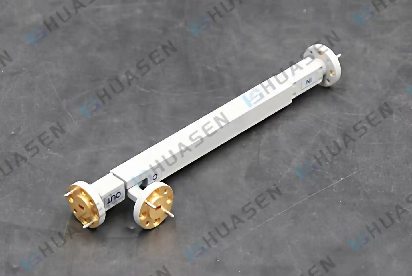
Our OEM/ODM Strengths: Three Decades of Engineering Microwave Solutions
Since 1993, Huasen Microwave has accumulated practical knowledge that only comes from solving real-world RF challenges across the telecommunications, aerospace, and defense sectors. This experience translates directly into superior OEM partnerships.
- Manufacturing Infrastructure: Our production facilities integrate precision CNC machining for waveguide components with advanced plating operations. When your application requires silver-plated brass housings for optimal conductivity, we control that process in-house. This vertical integration reduces lead times and maintains tighter tolerances—critical when directivity performance hinges on sub-millimeter coupling aperture positioning.
- R&D Capabilities: Our engineering team doesn't simply replicate existing designs. We've developed proprietary multi-hole coupling arrays that achieve directivity exceeding 40dB across octave bandwidths. For clients requiring extended frequency response, we employ Chebyshev distribution algorithms that flatten coupling factor variations to within ±0.5dB across your specified band. This expertise proves invaluable when your measurement system must characterize devices under test with minimal uncertainty.
- Quality Control Systems: Every directional coupler undergoes full four-port S-parameter characterization using calibrated vector network analyzers. We measure insertion loss, return loss, coupling factor, and directivity across temperature ranges that match your operating environment. Passive intermodulation testing ensures our couplers won't generate spurious signals in your high-power transmission paths—a requirement that telecom infrastructure providers cannot compromise on.
- Supply Chain Management: Component obsolescence disrupts production schedules. We maintain strategic relationships with dielectric material suppliers and connector manufacturers, ensuring stable availability of PTFE insulators and precision SMA, N-type, or K-connector interfaces. When you commit to a multi-year product lifecycle, our supply chain resilience protects your continuity.
- Scalability: Prototype quantities transition smoothly into production volumes. Whether you need 50 units for field trials or 5,000 annually for established product lines, our Directivity Coupler’s manufacturing processes scale without sacrificing the tight performance specifications that characterize low-volume builds.
Comprehensive Customization Options: Engineering Your Exact Specification
Physical design flexibility starts with housing configurations. Standard catalog couplers come in fixed form factors that rarely align with your mechanical constraints. We adapt dimensions to fit your rack-mount chassis, integrate mounting flanges that match your existing bolt patterns, and modify port orientations to simplify your RF routing. When space becomes constrained—common in airborne communication systems or drone-mounted radar—we compress footprints through high-density stripline architectures without degrading electrical performance.
Functional customization addresses your measurement system's operational requirements. Coupling factors range from 6dB for high-sample applications down to 50dB when you need minimal main-line disturbance. Directivity specifications tailored to your measurement uncertainty budget. If your application involves characterizing antenna return loss below -40dB, we engineer coupler directivity to 45dB or better, ensuring reflected power readings remain uncontaminated by forward signal leakage.
Technology choices impact both performance and cost. Coaxial directional couplers deliver broadband frequency response—we've produced units covering 500 MHz through 18 GHz in a single device. Waveguide couplers excel at millimeter-wave frequencies where coaxial transmission line losses become prohibitive. For clients developing 5G FR2 test equipment operating at 28 GHz or satellite communication systems at Ku-band, waveguide technology provides superior power handling and lower insertion loss.
Power handling ratings scale to your application's thermal environment. Base station monitoring requires continuous wave power ratings of 50 watts or more, with peak power capability reaching several kilowatts for pulsed radar applications. We thermal model our designs to ensure junction temperatures remain within safe limits, preventing dielectric breakdown that would compromise long-term reliability.
Branding integration extends beyond simple logo placement. We coordinate housing finishes, labeling formats, and documentation packages that reinforce your corporate identity. When your customers unpack their RF test system, every component reflects the professional image you've built.
Compliance certification requirements vary by target market and application domain. MIL-STD-810 environmental testing validates performance under shock, vibration, and temperature cycling for defense applications. RoHS compliance ensures European market access. We navigate these regulatory landscapes, delivering components with the certifications your product launch demands.
Packaging and shipping protocols adapt to your logistics requirements. ESD-protective containers, custom foam inserts, and calibration data sheets travel with each shipment. For high-value aerospace programs, we provide serialized traceability documentation that satisfies your AS9100 quality management systems.
The ODM Advantage: Co-Developing Next-Generation Measurement Architectures
Original design manufacturing partnerships unlock innovation beyond the adaptation of existing technologies. When you approach us with a measurement challenge that current coupler technologies cannot adequately address, our ODM process begins.
Consider a recent collaboration with a test equipment manufacturer on the directivity of a directional coupler power monitoring system for massive MIMO base stations. Their architecture required simultaneous sampling of 64 transmit paths with identical coupling factors and phase relationships. Standard couplers introduced unacceptable channel-to-channel variations in the directivity of a directional coupler that corrupted their beamforming calibration algorithms.
We co-developed a matched coupler array solution. Through electromagnetic simulation, we optimized a common coupling structure that achieved ±0.3dB amplitude matching and ±3-degree phase matching across all 64 channels. The design incorporated integrated temperature compensation that maintained these specifications across the -40°C to +85°C industrial temperature range.
This ODM approach delivered three critical advantages. They eliminated the cost and complexity of post-production trimming that individual couplers would have required. Time-to-market accelerated because our team's microwave expertise compressed their development cycle. The resulting intellectual property—jointly developed—created a defensible competitive advantage in their target market segment.
ODM partnerships prove particularly valuable when your application involves emerging frequency bands where mature component ecosystems don't yet exist. As 6G research pushes into sub-terahertz frequencies, existing measurement infrastructure struggles to maintain signal integrity. We're actively developing planar directional coupling structures that extend useful frequency response beyond 100 GHz while maintaining the mechanical robustness that test equipment demands.
Our Process: From Concept to Calibrated Component
The customization journey begins with technical dialogue, not sales presentations. We need to understand your measurement system architecture, the signal environments your couplers will encounter, and the performance metrics that define success for your application.
- Requirement Definition: You provide target specifications—frequency range, coupling factor, directivity, power handling, and environmental conditions. We probe deeper: What's your acceptable measurement uncertainty? Do phase-matched coupler sets matter for your application? Understanding these nuances prevents costly redesign cycles later.
- Conceptual Design: Our RF engineers evaluate multiple coupling topologies against your requirements. Coaxial architectures might offer cost advantages for moderate frequency ranges, while waveguide technology delivers superior performance at millimeter-wave bands. We present trade-off analyses that quantify how design choices impact performance, manufacturability, and unit cost.
- Electromagnetic Modeling: Advanced simulation tools model your custom coupler's S-parameters across frequency, temperature, and manufacturing tolerances. We identify potential resonances, optimize impedance matching networks, and predict passive intermodulation performance. This virtual prototyping dramatically reduces physical iteration cycles.
- Prototype Fabrication: Initial samples undergo rigorous characterization in our metrology laboratory. Full four-port S-parameter sweeps validate coupling factor flatness, return loss, and directivity against your specifications. High-power testing confirms thermal performance meets continuous wave and peak power ratings. When measurements reveal deviations from predicted performance, we refine the design and iterate.
- Design Validation: Once electrical performance meets specifications, environmental qualification begins. Temperature cycling, vibration testing, and humidity exposure verify your custom couplers will survive the conditions your measurement systems face. For defense and aerospace applications, we conduct full MIL-STD qualification testing with documented results.
- Production Transition: Manufacturing process documentation ensures production units replicate prototype performance. Statistical process control monitors critical dimensions. Ongoing testing of production samples maintains quality consistency across your order quantities.
- Technical Support: Our relationship extends beyond component delivery. When you're integrating our couplers into your system, questions arise about optimal grounding practices, connector torque specifications, or calibration procedures. Our applications engineers provide responsive guidance that accelerates your integration timeline.
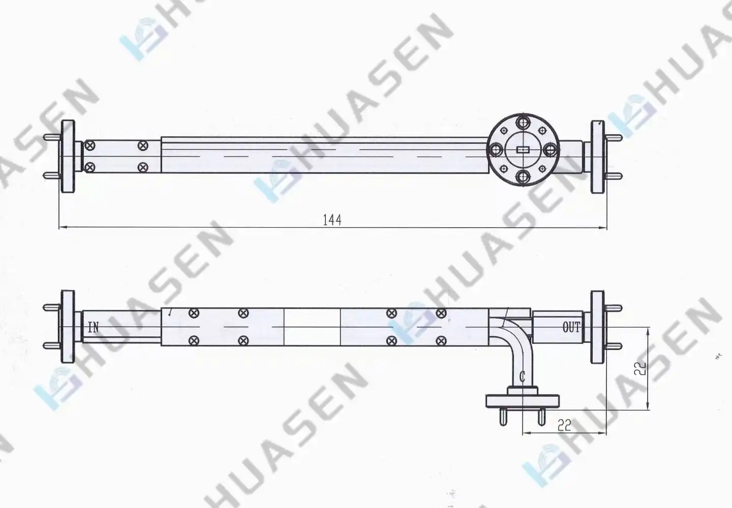
Benefits to You: Transforming Component Decisions into Competitive Advantages
Custom directivity coupler solutions deliver measurable value beyond the component itself. Measurement system accuracy improves directly through enhanced directivity and a flatter frequency response. When your test equipment exhibits tighter specifications, it commands premium positioning in competitive markets.
Inventory complexity decreases when a single custom coupler covers multiple frequency bands that previously required separate components. A simplified bill of materials reduces procurement overhead and minimizes assembly errors. For system integrators managing dozens of active projects simultaneously, this directivity of a directional coupler and operational simplification translates to faster deployment cycles.
Product differentiation strengthens when your measurement architecture incorporates capabilities competitors cannot easily replicate. That multi-channel matched coupler array? It becomes a selling point that resonates with sophisticated customers who understand how it improves their measurement confidence.
Reliability improvements reduce field failure rates and warranty costs. Our environmental qualification testing identifies potential failure modes before your customers discover them. Components engineered for your specific operating conditions outlast generic alternatives that sacrifice margin to address broad market segments.
Time-to-market acceleration occurs when you leverage our three decades of RF engineering expertise rather than building that knowledge internally. The prototype iterations we compress and the regulatory pathways we navigate, represent months of calendar time—often the difference between leading a market transition and arriving late to a maturing opportunity.
Cost optimization happens through multiple mechanisms. Design-for-manufacturability recommendations reduce per-unit production costs. Volume commitments across your product lifecycle qualify for pricing advantages that one-time purchases never achieve. Avoiding the hidden costs of component redesign—recertification testing, production line disruption, customer notification—preserves budget for genuine product innovation.
Conclusion
In conclusion, selecting the right OEM or ODM directivity coupler is essential for achieving accurate, reliable, and high-performance RF measurement systems. Custom-engineered solutions provide superior directivity, stable coupling factors, low insertion loss, and robust environmental resilience compared to standard catalog products. With decades of microwave engineering expertise, advanced manufacturing capabilities, and comprehensive customization services, Huasen Microwave helps businesses optimize measurement accuracy, accelerate product development, and strengthen market competitiveness. By partnering with an experienced manufacturer, system integrators and test equipment providers can transform component selection into a strategic advantage for long-term innovation and operational success.
FAQ
1. What directivity performance can custom couplers achieve?
Directivity performance scales with coupling architecture complexity and manufacturing precision. Standard catalog couplers typically deliver 15-20dB directivity, which proves adequate for basic power monitoring applications. Custom-engineered multi-hole coupling arrays achieve directivity exceeding 40dB or even 50dB across octave bandwidths. We've developed waveguide couplers for metrology applications where directivity reaches 55dB, enabling antenna return loss measurements below -50dB. The directivity level you need depends on your measurement uncertainty budget and the magnitude of load reflections in your system. Higher directivity requirements increase manufacturing complexity and cost, so we optimize designs to meet your specifications without unnecessary performance margin.
2. How do coupling factor tolerances affect measurement system accuracy?
The coupling factor directly determines the ratio between the sampled signal strength and main-line power. Variations in this ratio translate directly into power measurement errors. Standard couplers often specify ±1dB coupling factor tolerance, which may seem acceptable until you consider how it compounds with other system uncertainties. Custom directional couplers employing Chebyshev-optimized coupling arrays maintain ±0.5dB or tighter tolerances across specified frequency bands. For applications requiring traceable power measurements—calibration laboratories, transmitter certification testing—we provide couplers with individually characterized coupling factors documented across frequencies. This data enables measurement uncertainty calculations that satisfy ISO 17025 accreditation requirements.
3. Can directivity couplers operate in harsh outdoor environments?
Environmental resilience depends entirely on housing construction and sealing methods. Catalog couplers designed for benchtop laboratory use fail rapidly when exposed to moisture, temperature cycling, and UV radiation. Our custom outdoor-rated directional couplers employ sealed housings with IP67 ingress protection, corrosion-resistant plating, and temperature-compensated designs. We've qualified couplers for maritime communication systems operating in salt-spray environments and desert telecommunications infrastructure experiencing 70°C diurnal temperature swings. Material selection matters critically—PTFE dielectrics maintain stable electrical properties across temperature extremes, where cheaper plastics would introduce coupling factor drift. When your application involves outdoor or mobile platforms, specify the full environmental envelope during requirements definition so we can engineer appropriate protection.
4. What frequency ranges do custom directivity couplers cover?
Frequency coverage spans from HF bands through sub-terahertz ranges, though coupling technology choices vary across this spectrum. Coaxial directional couplers efficiently cover 10 MHz through 40 GHz, with ultra-wideband designs achieving decade bandwidths. Above 40 GHz, waveguide couplers deliver superior performance as coaxial transmission line losses become prohibitive. We've developed WR-28 waveguide couplers for Ka-band satellite communication systems at 26.5-40 GHz and WR-10 millimeter-wave couplers extending to 110 GHz for automotive radar test equipment. Emerging sub-terahertz applications between 100 and 300 GHz represent current research frontiers where planar coupling structures show promise. Your target frequency range significantly influences coupler architecture, so bandwidth requirements should appear early in technical discussions.
Partner with a directivity coupler manufacturer that understands your mission.
Your RF measurement systems represent a significant engineering investment and market opportunity. The directivity couplers embedded within those architectures deserve the same strategic consideration you apply to system-level design decisions.
Huasen Microwave brings specialized expertise that generic component distributors cannot match. We understand the physics governing directional coupling—how aperture spacing affects directivity, why dielectric constants shift coupling factors with temperature, and when waveguide modes corrupt isolation performance. This knowledge directly benefits your product's performance and reliability.
System integrators building telecommunications infrastructure gain a partner who comprehends the regulatory environment, power-handling demands, and long-term availability requirements that characterize multi-year deployment programs, including the use of a directivity coupler. Test equipment manufacturers access customization capabilities that transform their measurement accuracy into defensible competitive positioning. Research institutions developing next-generation communication technologies find responsive engineering support for exploratory frequency ranges where standard components don't exist yet.
Ready to engineer measurement solutions that exceed catalog specifications? Contact our applications team at sales@huasenmicrowave.com to discuss your custom directivity coupler requirements. We'll analyze your technical specifications, propose optimized coupling architectures, and outline a development timeline that aligns with your product launch schedule. Your measurement challenges deserve solutions engineered specifically for them.
References
1. Pozar, D.M. (2011). Microwave Engineering (4th ed.). Hoboken: John Wiley & Sons, Inc.
2. Rizzi, P.A. (1988). Microwave Engineering: Passive Circuits. Englewood Cliffs: Prentice Hall.
3. Bahl, I.J. (2003). Lumped Elements for RF and Microwave Circuits. Boston: Artech House Publishers.
4. Linkhart, D.K. (2014). Microwave Circulator Design (2nd ed.). Norwood: Artech House.
5. Collin, R.E. (2001). Foundations for Microwave Engineering (2nd ed.). New York: IEEE Press.
6. Gupta, K.C., Garg, R., Bahl, I., & Bhartia, P. (1996). Microstrip Lines and Slotlines (2nd ed.). Boston: Artech House Publishers.
Send Inquiry