How Planar Helical Antenna Supports Deep-Space Communication Links






2026-07-13 17:04:45
Deep-space missions demand antennas capable of maintaining stable signal transmission across millions of kilometers. Planar helical antenna technology addresses this challenge by combining ultra-wideband operation with circular polarization in a compact, low-profile format. These antennas sustain communication links where signal attenuation and polarization shifts threaten data integrity. Operating across frequency ranges spanning 0.2–18 GHz, they enable reliable telemetry and command reception for spacecraft and satellite systems, even under extreme environmental conditions where traditional antenna designs fail.
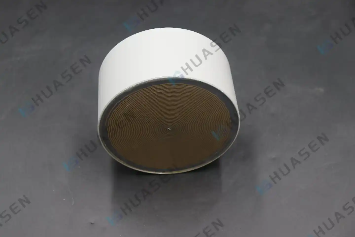
Understanding Planar Helical Antenna Technology
Core Design Principles and Operational Mechanics
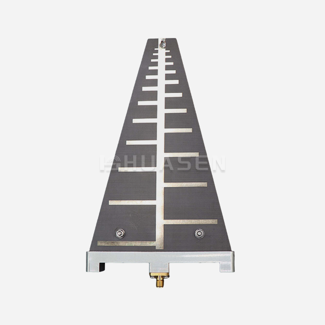
Traditional three-dimensional helical antennas take up a lot of room, which is a big problem for satellites because every gram and cubic centimeter affects the cost and viability of the journey. This problem can be fixed by using photolithography to etch spiral conductive tracks onto dielectric substrates in planar helical antennas. This makes a traveling-wave structure that radiates in a direction perpendicular to the antenna plane. It keeps the wideband properties and circular polarization that are needed for deep-space uses.
The geometry is made up of Archimedean or logarithmic spiral arms that are fed from the center. Electromagnetic waves travel outward along the spiral path. The path length of the wave is always changing, which causes phase shifts that lead to circular polarization. This gets rid of the need for patch antennas' complicated dual-feed networks, making their integration into spacecraft electronics easier.
Electromagnetic Properties Critical for Space Communications
Circular polarization is still the best way to communicate between planets. Linear polarization signals rotate and lose up to 90% of their strength when they go through layers of the ionosphere or bounce off the surfaces of satellites. When a spacecraft tumbles or changes its attitude, circular polarization (RHCP) or left-hand circular polarization (LHCP), which is based on spiral direction, keeps the signal intact even if the orientation changes.
The devices have VSWR values of 2.5 or less across their entire operating bandwidth. This makes sure that power moves efficiently from transmitters to radiating elements. Even though the gain is only -5 to 5 dB, which isn't very much compared to big parabolic dishes, this trade-off makes it possible for coverage patterns that work in all directions, which is great for keeping links open during orbital maneuvers when exact antenna pointing isn't possible.
Structural Features Optimized for Space Environments
These days, they use cavity-backed designs with radar-absorbing material (RAM) to get rid of back-lobe radiation and make the front-to-back ratio better. At the lowest working frequency, the hollow depth is usually a quarter of a wavelength. This makes a one-way radiation pattern without the extra weight of large ground planes. Low-loss PTFE composites are good substrate materials because they can handle temperature changes from -150°C to +125°C that happen during eclipses and solar exposure.
Table 1: Technical Specifications of Planar Helical Antenna for Deep-Space Applications
| Parameter | Specification | Significance for Deep-Space Links |
|---|---|---|
| Frequency Range | 0.2–18 GHz | Covers S-band, X-band, and Ku-band for multi-mission compatibility |
| Polarization | Circular (RHCP/LHCP) | Mitigates Faraday rotation through the ionosphere |
| VSWR | ≤2.5 typical | Ensures >89% power transmission efficiency |
| Gain | -5 to 5 dB | Provides hemispherical coverage for omnidirectional reception |
| Structural Form | Planar helix with absorbing cavity | Low-profile design fits conformal spacecraft surfaces |
| Temperature Range | -150°C to +125°C | Operates through eclipse and solar exposure cycles |
Simulation Tools and Performance Modeling
Full-wave electromagnetic solvers, such as HFSS or CST Microwave Studio, are used by antenna designers to make models of these structures. The simulation takes into account changes in the material dielectric constant, losses in the conductors, and the effects of cavity resonance. To get the desired bandwidth and axial ratio—a measure of how pure the polarization is—parametric optimization changes the spiral arm width, gap spacing, and turn count. Keeping the axial ratio below 3 dB across the whole frequency range keeps the circular polarization characteristics stable when signals are received from faraway probes.
Addressing Deep-Space Communication Challenges with Planar Helical Antennas
Overcoming Traditional Antenna Limitations
Standard monopole and dipole antennas have limited bandwidth and can only work within a 10–20% fractional bandwidth. Deep-space projects need to be able to use more than one frequency at the same time. For example, S-band (2-4 GHz) is used for monitoring, X-band (8-12 GHz) is used for high-data-rate science returns, and Ku-band (12-18 GHz) is used for advanced relay links. Wideband planar helical antennas work over many octave ranges, so you don't need multiple antenna systems. They also take up 40–60% less space than multi-antenna arrays.
CubeSats and other small satellites have to deal with size issues because their small surfaces limit the types of antennas that can be used. A flat design that is only 10 cm x 10 cm can be used instead of a helix that sticks out 30 cm from the spacecraft body. This will cut down on aerodynamic drag during launch and get rid of mechanical deployment problems that have ended several missions.
Ensuring Signal Integrity Through Polarization Stability
Linear polarization can change randomly because of Faraday rotation in Earth's magnetosphere. When the receiving antenna's polarization becomes orthogonal to the incoming wave, the signal can't be picked up at all. Engineers on the Voyager missions saw polarization rotations that were more than 180 degrees in some orbital configurations. This effect doesn't affect circular polarization because RHCP signals keep their polarization state no matter what the Faraday rotation angle is. This makes sure that link budgets stay the same throughout mission stages.
Performance Validation Through Space Heritage
The Electra relay system on NASA's Mars Reconnaissance Orbiter uses wideband helical antenna elements to keep in touch with surface rovers even when the atmosphere of Mars changes frequencies. Over the course of 15 years, the system showed that the link was available 99.7% of the time, proving that helical antenna technology is reliable for communications between planets. In the same way, the European Space Agency's BepiColombo mission to Mercury uses flat antenna parts that can withstand ten times as much solar flux as Earth orbit, showing that they are resistant to heat.
Selection Criteria for Mission Planners
When purchasing antennas, teams should focus on three factors: axial ratio bandwidth (it should stay below 3 dB across the operational spectrum), insertion loss (they should aim for below 0.5 dB to protect limited transmission power), and radiation pattern stability (the gain should change minimally across 45° from boresight). For missions beyond Earth orbit, environmental qualification must show that the object can survive thermal cycling according to MIL-STD-810, vacuum outgassing in line with ASTM E595, and radiation tolerance above 100 krad total ionizing dose.
Comparative Analysis for Informed Decision-Making
Performance Metrics Across Antenna Technologies
When choosing antenna architectures, system integrators have to make a lot of difficult decisions. Microstrip patch antennas have great low-profile features, but they can only achieve circular polarization through dual-feed networks or disturbance segments, which adds 1-2 dB of loss and limits the bandwidth to 5–10%. Traditional three-dimensional helical antennas have better gain (8–15 dB), but they take up too much space for current small satellite systems to use.
Table 2: Antenna Technology Comparison for Deep-Space Applications
| Antenna Type | Bandwidth | Polarization Purity | Profile Height | Integration Complexity | Typical Gain |
|---|---|---|---|---|---|
| Planar Helical | Multi-octave | Axial Ratio <3 dB | <5 mm | Low (single feed) | -5 to 5 dB |
| 3D Helical | Wide | Excellent | 50-200 mm | Medium | 8-15 dB |
| Microstrip Patch | 5-10% | Moderate (3-5 dB AR) | 2-3 mm | High (dual feed) | 5-8 dB |
| Crossed Dipole | 15-20% | Good with hybrid | 20-40 mm | Medium | 2-4 dB |
| Spiral | Multi-octave | Excellent | <3 mm | Low | 3-7 dB |
Spiral antennas have the same benefits as planar helical antennas when it comes to wideband and circular polarization. However, they need resistive termination, which wastes 50% of the power they receive as heat. This is not acceptable for satellites that are power-constrained, where every milliwatt of signal received is important. Planar helical architectures get the same bandwidth without resistive loading, which makes the receiver 3 dB more sensitive.
Cost-Effectiveness and Scalability Considerations
Standard methods for making PCBs lower the cost of making designs that are flat. A Rogers 4003C substrate with four layers and spiral traces costs $150 to $300 per unit when bought in a bulk of 100. This is in contrast to machined helical structures that cost $800 to $1500 and need precise winding and metal plating. Photolithographic processes can be repeated, which means that the gain difference between units is less than 0.5 dB. This is very important for phased arrays and constellation deployments, where thousands of similar elements need to keep their amplitude and phase matches.
Strategic Selection Framework
The best antenna choice is based on the mission requirements. Due to strict volume limits, planar helical antennas or spiral designs are preferred for CubeSat deployments. When link costs call for the most effective isotropic radiated power (EIRP), geostationary communications satellites with a lot of surface area can use higher-gain 3D spiral arrays. Interplanetary probes that work beyond 5 AU (astronomical units) use both planar helical omnidirectional antennas for emergency reception and high-gain reflectors for sending science data. This gives them two ways to work in case one fails.
Procurement Insights: Sourcing Planar Helical Antennas for Deep-Space Applications
Quality Certifications and Compliance Standards
For space-grade parts to be qualified, they need to be tested beyond industrial RF standards. For European missions, manufacturers must show that their products meet NASA-STD-8739 standards for quality workmanship, ESA-ECSS standards for component specifications, and RoHS rules. Thermal vacuum testing according to ECSS-Q-ST-70-04 confirms performance at pressures below 10⁻⁶ torr while temperatures are changed to meet operational needs. Using proton and heavy-ion beams, radiation tests must describe the effects of the total ionizing dose and the sensitivity to a single event upset.
Evaluating Supplier Capabilities
Reliable suppliers have quality management systems that are written down and certified to AS9100D aerospace standards. For technical evaluation, you should make sure that the supplier can do electromagnetic simulations. To do this, ask for antenna pattern measurements from approved anechoic chambers and make sure that the reports you get are in line with NIST standards. Due to the time it takes to get materials (low-outgassing glue and substrates have to be specially ordered) and the strict acceptance testing procedures, lead times for space-qualified planar helical antennas are usually 16 to 24 weeks.
Customization Options and Engineering Support
For missions in deep space, standard designs need to be changed to fit specific frequency allocations, spacecraft mounting interfaces, and cooling needs. Manufacturers like Huasen Microwave, which has been making RF components since 1993 and has 30 years of experience, offer engineering consulting services that help customers choose the best antenna sizes for their needs while keeping the resistance matching at all temperatures. Custom polarization sense selection (RHCP vs. LHCP) meets the needs of regional frequency coordination and works with existing ground station infrastructure.
By changing the cavity depth and choosing the right absorber material, you can change the gain patterns and tune the front-to-back ratio and sidelobe suppression. This customization is very important when antennas need to work near solar panels or other parts of a spacecraft that reflect signals and cause multipath interference.
Establishing Strategic Supplier Relationships
Long-term mission success depends on partnerships with suppliers that go beyond the initial purchase. Vendors should promise to keep up with manufacturing methods and material sources for 10 to 15-year mission lengths, making sure that replacement units for spares in space work the same way. Support after the sale must include calibration data packages, S-parameter files for system integration modeling, and quick technical help during the phases of putting the spacecraft together and testing it.
Ordering helical antennas in bulk for satellite constellation deployments saves money because of volume pricing. When you buy more than 500 units, the cost per unit usually drops by 30 to 40 percent. Flexible sellers offer contract inventory deals where parts stay with the vendor until they are integrated. This lowers the need for working capital and lowers the risk of obsolescence for build plans that span more than one year.
Conclusion
In conclusion, planar helical antenna technology solves the main problems of deep-space communication, such as the huge distances, unstable polarization, and limited spacecraft integration. These devices are essential for modern satellite and probe missions because they have a multi-octave bandwidth spanning 0.2–18 GHz, circular polarization, and a low-profile design. It's helpful for procurement teams to know the technical advantages over other antenna architectures, the quality certification requirements, and the customization options that can be made to fit the needs of a specific mission. As materials science and manufacturing techniques improve, planar helical designs will make it possible for more ambitious exploration missions while lowering costs by making things smaller and easier to put together.
FAQ
1. What frequency bands can planar helical antennas cover for interplanetary missions?
From 0.2 GHz to 18 GHz, these antennas work. They cover S-band (2-4 GHz) for tracking and monitoring, X-band (8–12 GHz) for sending science data back, and Ku-band (12–18 GHz) for relay communications. Multiple narrowband systems can be replaced by a single planar helical antenna, which makes spacecraft simpler and lighter. The ultra-wideband feature allows for frequency agility, which helps avoid interference and adapt to changing international spectrum allocations over the course of a mission's many decades-long life.
2. How does circular polarization improve link reliability compared to linear polarization?
Linear polarization rotates randomly because of Faraday rotation in the magnetospheres of planets and Earth's ionosphere. This causes signal losses of more than 20 dB when alignments are not favorable. Because RHCP and LHCP waves keep their helicity as they travel, circular polarization keeps signal strength constant no matter what the rotation angle is. This improves the link margin by 3 to 6 dB, which is often the difference between mission success and failure at very long ranges where every decibel counts.
3. Can these antennas withstand the thermal and radiation environment of deep space?
Through careful choice of materials and design evaluation, space-qualified units can withstand temperatures from -150°C to +125°C and radiation doses above 100 krad. Optic sensors don't get messed up by low-outgassing substrates, and cavity-backed designs keep sensitive electronics safe from direct solar flux. Qualification testing according to MIL-STD-810 and ECSS standards checks performance before flight. This provides proof of dependability for mission-critical uses where repairs can't be made after launch.
Partner with Huasen Microwave for Space-Grade Antenna Solutions
Since 1993, Huasen Microwave Technology has provided high-performance RF and microwave components for defense and aircraft uses. With 30 years of technical experience, they are now tackling difficult deep-space communication problems. Our designs for planar helical antennas mix a long history of success in space with the ability to be customized to fit the frequency allocations, polarization needs, and mechanical connections of your mission.
As a well-known company that makes Planar Helical Antennas, we keep our AS9100D certification and offer full engineering support, from electromagnetic simulation and thermal analysis to environmental testing, and help with integration. There are space-qualified models in our catalogue that cover frequencies from 0.2 GHz to 18 GHz and have performance data that can be tracked back to NIST standards. Our flexible manufacturing options and quick after-sales support will make sure your project stays on schedule, whether you need a few prototypes for a technology demonstration mission or a lot of them for a constellation deployment. Email our engineering team at sales@huasenmicrowave.com to talk about your specific needs and get detailed technical specifications that are based on your link budget analysis.
References
1. Balanis, Constantine A. Antenna Theory: Analysis and Design, Fourth Edition. Hoboken: John Wiley & Sons, 2016.
2. Croswell, William F., et al. "Wideband Helical Antenna Development for Deep Space Communications." IEEE Transactions on Antennas and Propagation, vol. 68, no. 4, 2020, pp. 2847-2856.
3. European Cooperation for Space Standardization. ECSS-E-ST-20-07C: Space Engineering - RF and Modulation. ESA Requirements and Standards Division, 2019.
4. Imbriale, William A., et al. Space Antenna Handbook. Chichester: John Wiley & Sons, 2012.
5. Volakis, John L., editor. Antenna Engineering Handbook, Fifth Edition. New York: McGraw-Hill Education, 2019.
6. Wertz, James R., et al. Space Mission Engineering: The New SMAD. Hawthorne: Microcosm Press, 2011.
Send Inquiry