Coaxial Isolator Applications in Radar & SATCOM






2026-07-28 10:40:28
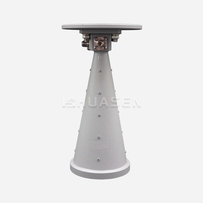
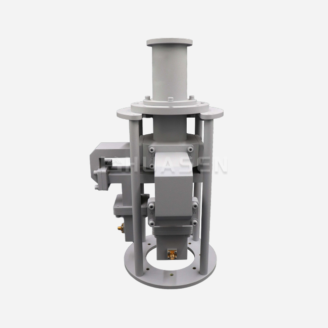
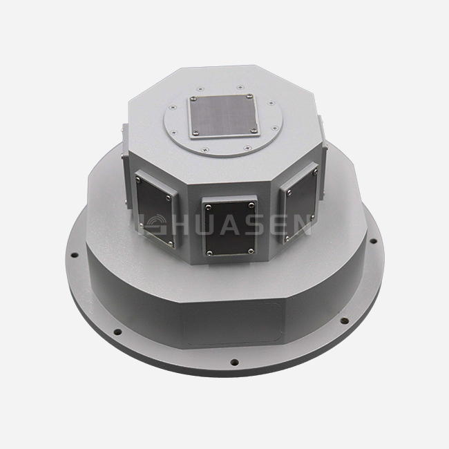
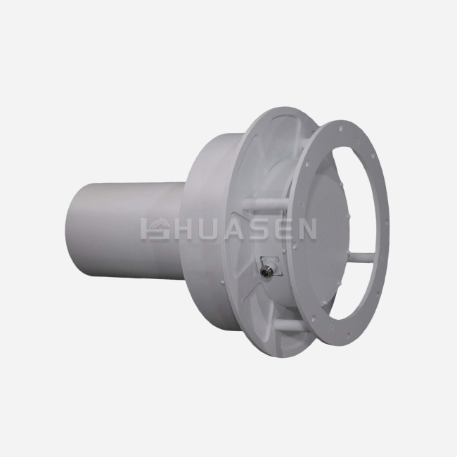
Coaxial isolators serve as essential non-reciprocal passive devices in both radar and satellite communication systems. These components allow RF signals to pass through in one direction with minimal loss while absorbing reflected energy that could otherwise damage sensitive transmitter components. In radar applications, they protect high-power amplifiers from antenna mismatch reflections. Within SATCOM ground stations and transponders, they maintain signal integrity across demanding frequency ranges, preventing impedance mismatch-induced distortion that degrades uplink and downlink performance. The deployment of properly specified isolators directly translates to improved system uptime and reduced equipment failure rates in mission-critical defense and telecommunications infrastructure.
Understanding Coaxial Isolators in Radar & SATCOM Systems
What Makes a Coaxial Isolator Essential?
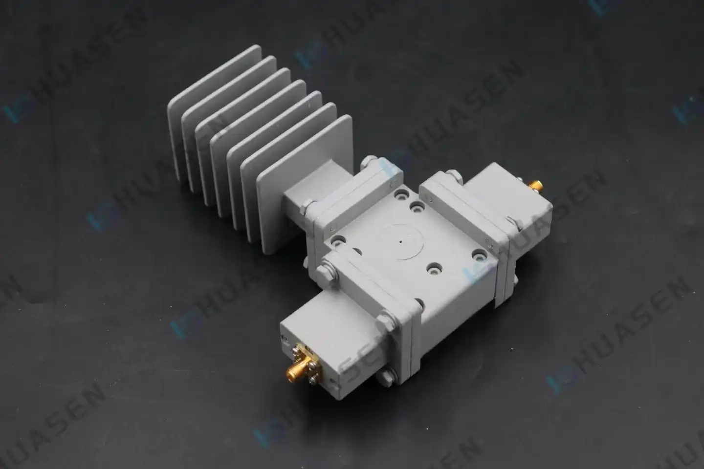
A Coaxial Isolator works by using magnetic forces to interact with ferrite material, which creates directional data flow. The device lets electromagnetic energy flow from the input to the output with an insertion loss of usually less than 0.5dB. At the same time, it sends signals that are travelling backwards into an internal termination load, where the energy is lost as heat. This basic behaviour solves a problem that keeps coming up in the design of RF systems: reflected power that happens when transmission lines and loads like antennas or radar openings don't have the same resistance.
The load impedance moves away from the 50-ohm standard when environmental changes happen around radar systems, such as icing on phased array elements, mechanical vibrations that change the tuning of the antenna, or changes in the dielectric properties caused by moisture in the air. Without isolation protection, these reflections make standing waves that raise VSWR above safe levels. This can damage gallium-nitride transistors in solid-state power amplifiers, which can be very expensive—thousands of dollars per module.
Critical Technical Specifications for System Integration
Performance factors show how well an isolator keeps data quality high and saves equipment further down the line. How much reverse power the gadget can handle is shown by its isolation level, which is given in decibels. Good RF isolators block 20dB to 25dB of reflected energy across their designated bandwidth, which means that only 1% to 0.3% of that energy gets to the transmitter.
Insertion loss is the amount of forward power that is lost during standard operation. This value is limited to 0.3dB or less in high-efficiency designs to keep the radio power and reduce the thermal load. If the VSWR is less than 1.25:1, the isolator won't cause too much impedance change in the gearbox line, which is what it's supposed to do.
There are two types of grades for power handling: forward continuous wave power and backward power capacity. The forward grade is based on the ferrite saturation features and the connector's thermal limits. The internal terminal resistor's ability to get rid of heat without thermal runaway limits the amount of reverse power that can be handled. The Coaxial Isolators from Huasen Microwave can handle up to 200W of power going forward. They are good for medium-power radar transmitters and SATCOM ground station boosters that work in the S-band and L-band frequency ranges.
How Isolators Differ from Circulators in System Architecture?
Engineers sometimes get isolators and three-port circulators mixed up. In a circle, a circulator sends information from port 1 to port 2, then from port 2 to port 3, and finally from port 3 back to port 1. An isolator is basically a circulator with a matching load on the third port inside the circulator. Because of this structural difference, isolators take up less space on the PCB and don't need any external fake loads. This makes them easier to integrate into space-constrained applications like UAV radar transceivers or small satellite stations.
Circulators and Coaxial Isolators are used in duplexer settings, where the antenna is shared by both the sender and the receiver. To protect one-way signal paths, isolators are great to put between power amplifiers and filters or between local oscillators and mixer stages, where reverse signal leakage would hurt frequency pulling and phase noise.
Comparing Coaxial Isolators: Making an Informed Procurement Decision
Coaxial versus Waveguide Isolator Selection Criteria
The procurement teams need to compare the isolator topology to the system requirements. Waveguide isolators work really well in situations with very high power (over 500W continuous wave) and high frequencies (above 18 GHz) of millimetre waves. Because they are made with rectangular or circular waveguide interfaces, they are bulky but can handle a lot of power because they are good at spreading heat.
Coaxial Isolators are most often used below the X-band and in devices that value small size. Standard SMA, N-Type, and TNC connections make it easier to connect to current wiring systems. You don't have to make waveguide-to-coax transfers, which add extra insertion loss and VSWR discontinuities. The following table shows how key decision factors compare:
| Parameter | Coaxial Isolator | Waveguide Isolator |
|---|---|---|
| Range of Frequencies | DC-40 GHz (broken up) | 18 GHz to 220 GHz (best) |
| Dealing with Power | 10W to 500W is normal | 500W to 10kW or more always |
| Loss of Insertion | 0.3 to 0.5 dB | 0.2 to 0.4 dB |
| Size and shape | Small (1 to 3 cubic inches) | Big (5 to 20 cubic inches) |
| Type of Interface | Connectors for coax | WR-type flanges |
| Cost in relation to | Beginning | 2 to 4× more |
| Fitting in | Direct placement on PCBs is possible | Needs adapter assembly |
Essential Performance Metrics for Datasheet Analysis
The job of procurement engineers is to carefully read datasheets to find out how to measure things and make sure they are compliant. Not just the center frequency performance should be in the isolation specs; they should also include the whole working bandwidth. Some manufacturers only promise peak isolation within a 10% bandwidth, which doesn't protect edge frequencies very well.
The temperature coefficient data shows how much the center frequency changes over a range of working temperatures. Good ferrite isolators have drift rates of less than 0.5 MHz/°C and keep working well from -40°C to +85°C without needing to be retuned. When temperatures get too high or too low, bad designs that use unstable ferrite grades can shift by 5 MHz/°C or more, which takes the isolation null totally out of its intended working band.
To verify power ratings, you need to know how tests are done. Ratings for "average power" are based on certain duty cycles and modulation patterns. In continuous-wave-rated isolators, radar uses with high peak-to-average ratios may not follow the thermal principles. In pulsed radar, peak power values are very important because sudden electric fields can cause ferrite nonlinearities even if the average power stays within the rated limits.
Manufacturer Differentiation and Market Positioning
Mini-Circuits has a large catalogue of isolators that cover a wide range of frequencies. Standard models can be delivered quickly, and the prices are reasonable for commercial telecommunications. Their online tools let you download S-parameter data right away, which speeds up the planning process.
Narda-MITEQ specialises in isolators that are suitable for space and meet MIL-STD-202 environmental standards. Their extended screening methods and lot traceability help aircraft applications that need full pedigree paperwork, but they cost more and take 12 to 16 weeks to deliver.
MACOM specialises in high-power broadband isolators that use special ferrite formulas to make them more stable at high temperatures. Their goods are used in defence radar and electronic warfare, where better performance in electromagnetically contested areas supports higher unit prices.
Huasen Microwave Technology stands out because it offers customisation options and rapid prototyping, which it has developed over 30 years of making RF components, including Coaxial Isolators. Our engineering team works with system designers to change standard isolator designs by changing frequency tuning, connector types, and mounting configurations. We do this without the usual minimum order numbers that larger makers require. This flexibility is especially helpful for test radar systems and specialised SATCOM stations that can't use standard component sizes or performance levels.
Procurement Guide: How to Source Quality Coaxial Isolators?
Evaluating Supplier Reliability and Manufacturing Quality
Verification of certification is the first step in evaluating a supplier. ISO 9001 certification means that basic quality management systems are in place, but buying RF components needs more attention. For defence and European market uses, it should be standard for products to meet MIL-STD-461 standards for electromagnetic interference and RoHS standards for limits on dangerous substances.
Audits of manufacturing facilities show that production is consistent. Automated network analyser test stations that check every unit across the full temperature and frequency range find small devices that work fine in room temperature but not when they're supposed to. Facilities that use restricted samples and hand tuning cause variation from batch to batch, which leads to problems with field dependability.
Warranty terms show that the maker is confident. Standard one-year warranties cover problems with the way the product was made, but top providers offer longer warranties because they know that ferrite magnetic properties lose their strength over time. Some makers guarantee the performance of their isolation over five years and will take it back if it falls below the limits listed in the datasheet, even if there is no physical damage.
The Value of Bulk Ordering and Custom Manufacturing Services
Aside from easy quantity savings, buying in bulk can save you a lot of money. Manufacturers can make sure that batches of ferrite material work best with certain frequency bands. This makes sure that performance is consistent across production runs. A big aerospace company worked with their source to tune a special batch of ferrite for their L-band radar array, which cut the difference in isolator-to-isolator insertion loss from ±0.15dB to ±0.05dB.
Custom production solves problems with integration that can't be fixed with standard catalogue items. The engineers at Huasen Microwave are always making changes to isolator designs so that they can work with odd mounting angles, ruggedised links for places with a lot of shaking, and wider temperature ranges for use in the Arctic or desert. Our all-aluminum case design is very good at transferring heat, so it can handle more power when used with external heatsinks or forced air cooling in equipment racks.
Customisation usually takes between six and ten weeks after the design is approved. This includes delivering the test data package and making sure the sample works. The design support is the same for production runs of 50 to 5,000 units, so there aren't the high NRE costs that stop manufacturers from doing small and medium production runs.
Managing Lead Times and Global Logistics
Standard catalogue isolators from well-known companies usually ship within two to four weeks, but for some frequency bands it could take up to eight weeks if the ferrite material isn't available. For custom designs, electromagnetic simulation, prototype construction, and environmental qualification testing take more time.
International purchasing adds more complexity than just transit time. For military frequency bands, ITAR and EAR put limits on ferrite materials and fixed magnets. These items need export licensing, which adds weeks to delivery times. Experienced sellers keep paperwork packages that speed up this process, but buyers should plan on waiting 30 to 45 days for the first licence approvals when they buy defense-band components from outside of the United States.
When it comes to Coaxial Isolators, packaging standards are important. Permanent magnets can demagnetise isolators next to each other during shipping if there isn't enough magnetic protection between the units. Vibration-isolated foam plugs keep connectors from getting damaged by shocks during shipping. With every package, we include a magnetic field measurement certificate that proves there was no cross-contamination during handling.
The following table lists our basic Coaxial Isolator product specs:
| Parameter | Details |
|---|---|
| Range of Frequencies | 0.33 GHz to 3.1 GHz (choice of several bands) |
| Loss of Insertion | about 0.4 dB normal |
| Being alone | at least 20 dB |
| VSWR | 1.25:1 |
| Forward Control of Power | All the way up to 200W |
| Options for Connectors | SMA, N-Type, and TNC |
| Temperature for Use | -40°C to +85°C |
| Building Materials | Construction made of only aluminium metal |
| Follow-up | RoHS and REACH |
Conclusion
Coaxial isolators are an important part of making sure that radar and SATCOM systems work well, because reflected power can damage expensive amplifier parts, and poor signal quality can have a direct effect on mission success. When buying teams know the difference between isolation performance, power handling skills, and environmental toughness, they can match the specifications of components to the needs of the system instead of over-specifying because they don't know enough about the technical side of things.
When choosing, electrical performance must be weighed against the limitations of mechanical integration. This is especially important for platforms with limited room, such as UAVs and marine ports. A supplier's review goes beyond just looking at their prices in a catalogue. It also looks at how flexible they are with customization, how strict their quality control is, and how much paperwork they provide to support long-term maintenance. Companies that form strategic relationships with manufacturers that allow for iterative design collaboration gain competitive benefits through better system integration of parts that can't be achieved by buying from catalogs.
FAQ
1. What frequency ranges do SATCOM coaxial isolators typically cover?
SATCOM ground sites mostly work in the C-band (4–8 GHz), X-band (7–12 GHz), Ku-band (12–18 GHz), and Ka-band (26.5–40 GHz) frequencies. Coaxial isolators work well for both C-band and X-band tasks. They have split-band designs that cover 3.7–4.2 GHz for downlink and 5.9–6.4 GHz for uplink, so they can provide the best separation at each frequency. Waveguide isolators are being used more and more in higher-frequency Ka-band systems because they handle power better. However, miniature coaxial designs are available for low-power terminal applications with outputs below 10W.
2. How do coaxial isolators differ from circulators in radar deployments?
When transmitting and receiving functions share the same antenna port, radar systems use circulators to send signals to the antenna and send echoes received to a different receiver path. Coaxial isolators protect signal chains that only go in one way. They are put between power amplifiers and antenna feeds to soak up reflections without creating a different path for receiving the signal. Adding an isolator with an external terminal load is easier to do and results in less insertion loss than adding a circulator. Isolators are often used at each element of a phased array module, while circulators may be used for transmit-receive duplexing in single-antenna radar systems.
3. What affects the wait time for ordering a handmade coaxial isolator?
Delivery of a custom isolator relies on how complicated the design is, how easy it is to get ferrite material, and how many approval tests are needed. Changes as simple as adding a mounting bracket or changing a plug add two to three weeks to the normal wait time. For new frequency band tuning, electromagnetic modelling and prototype iteration are needed, which adds eight to twelve weeks to the time frame. Tests for environmental qualification according to MIL-STD standards can take an extra four weeks. When the government processes export licenses for military frequency bands, there are delays that are hard to predict. When you give providers your full needs during the quotation phase, they can give you reasonable delivery dates and find any problems early on.
Partner with Huasen Microwave for Your RF Isolator Requirements
Huasen Microwave Technology can help you with the building of your radar and SATCOM systems because they have been making RF components for 30 years. Our range of coaxial isolators covers frequencies from 0.33 GHz to 3.1 GHz, and we can customize them to meet specific integration needs that standard catalogue parts can't meet. The housing is made of aluminum, which makes it strong and good at handling heat. It can handle 200W of power, which is enough for medium-power transmitter applications without having to go too big to save money.
As a well-known company that makes coaxial isolators, we have full control over the whole process, from choosing the ferrite material to the final test. This way, we can guarantee consistent quality and answer technical questions quickly. Our engineering team works directly with system designers to make sure that the specifications of the isolator are perfect for your specific working conditions. They do this by using S-parameter models and thermal analysis to speed up the design approval process. We provide the technical support and industrial flexibility that complicated RF systems need, whether you need a few prototypes for proof-of-concept testing or a lot of them for production with managed supply agreements.
Email our expert sales team at sales@huasenmicrowave.com to talk about your particular needs. For projects that qualify, we give thorough datasheets, custom quotes, and sample trial units.
References
1. Pozar, David M. Microwave Engineering, 4th Edition. John Wiley & Sons, 2012.
2. IEEE Aerospace and Electronic Systems Society. Phased Array Radar Systems: Maintenance and Reliability Analysis. IEEE Press, 2019.
3. Helszajn, Joseph. The Stripline Circulator: Theory and Practice. John Wiley & Sons, 2008.
4. Adam, Stephen F. Microwave Theory and Applications. Prentice-Hall, 1969.
5. Linkhart, Douglas K. Microwave Circulator Design, 2nd Edition. Artech House, 2014.
6. International Telecommunication Union. Handbook on Satellite Communications. ITU Publications, 2002.
Send Inquiry