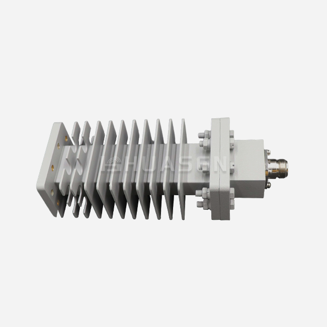
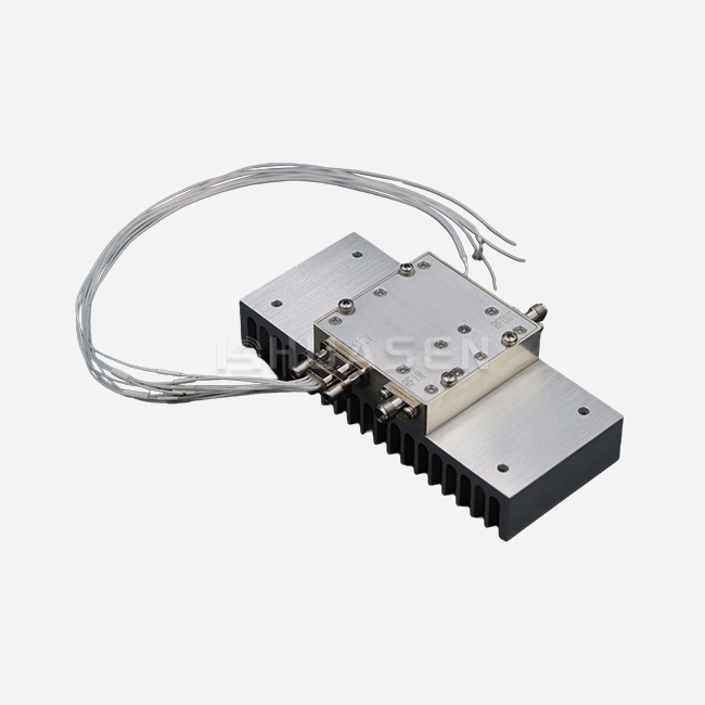
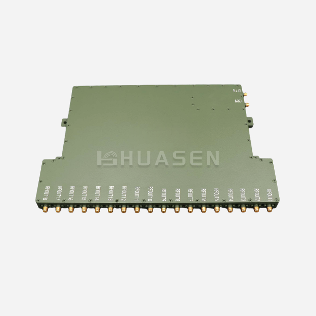
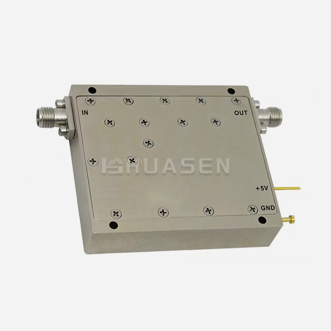
Coaxial Fixed Attenuator Materials: Why They Matter






2026-07-27 10:02:11
When choosing RF components for mission-critical infrastructure, material selection stands as the dividing line between reliable operation and costly system failures. The materials inside a coaxial fixed attenuator directly shape its attenuation accuracy, power handling capacity, thermal stability, and lifespan across demanding environments. Whether deployed in 5G base stations, satellite ground terminals, or aerospace radar systems, understanding why specific materials matter enables procurement managers and RF engineers to make informed decisions that protect both performance and investment. Material quality determines whether your attenuator maintains consistent signal control or becomes the weakest link in your microwave system.
Understanding Coaxial Fixed Attenuator Basics
Coaxial fixed attenuators lower the intensity of a radio frequency signal by a set number of decibels without changing the phase or pattern. In microwave and millimeter-wave uses, these inactive parts are used to level signals, protect receivers, and calibrate measurements with great accuracy.
How Does Attenuation Work in RF Systems?
The gadget uses resistor networks, usually in the form of T-pad or Pi-pad arrangements, that are built into a coaxial transmission line that is matched to a characteristic resistance of 50 Ohms. When RF energy goes through, the resistive parts give off extra power as heat while keeping the impedance matching to keep the voltage standing wave ratio (VSWR) as low as possible. This controlled energy absorption keeps sensitive receivers from overheating, increases the dynamic range of test equipment like vector network analyzers, and creates gaps between circuit stages that are stacked on top of each other. Values of attenuation usually fall between 3 dB and 50 dB, and accuracy requirements like 0.5 dB are very important for precise uses.
Key Applications Driving Material Requirements
Low passive intermodulation (PIM) performance is needed in distributed antenna systems with high-power amplifiers and optical transceivers for telecommunications infrastructure. For defense and aerospace radar calibration sets, attenuators are needed that can handle vibration, changes in altitude, and thermal shock from -55°C to +125°C while keeping link budgets fixed. In labs, these parts are used as VNA calibration standards because signal flatness and phase linearity are necessary for reliable S-parameter readings.
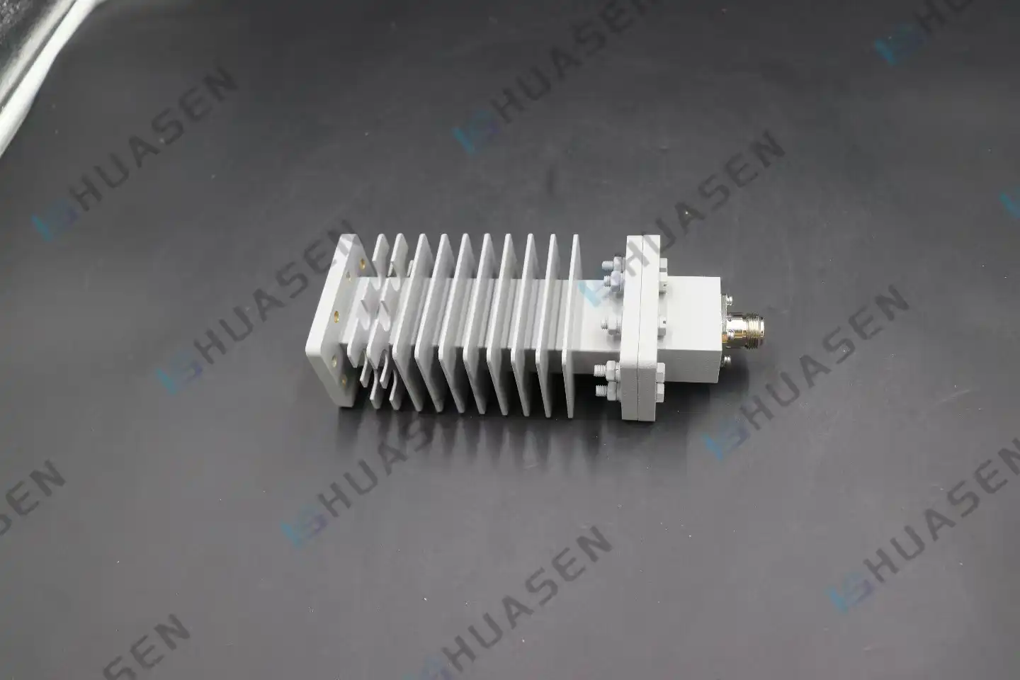
Table 1: Huasen Microwave Coaxial Fixed Attenuator Specifications
| Parameter | Specification Range |
|---|---|
| Frequency Range | DC - 18 GHz |
| Attenuation Values | 3 dB – 50 dB |
| Power Capacity | 1W to 500W |
| Connector Types | N-50J/K, SMA (compatible with mainstream systems) |
| Primary Applications | Microwave communications, broadcast TV, RF measurement |
| Core Functions | Signal stability, overload prevention, measurement accuracy enhancement |
These specs show the strict operating requirements that determine which materials to choose. To cover a wide range of frequencies, from DC to Ku-band, coaxial fixed attenuator resistive elements need to be very good at flattening frequencies. At the same time, building materials need to be able to handle power levels from 1W to 500W and be good at conducting heat and releasing it.
Why Material Quality Determines Attenuator Performance?
When it comes to RF systems, the choice of material sets the stage for all performance metrics that matter. The resistive films, housing metals, and dielectric surfaces all play a part in how well an attenuator keeps its decibel drop across a wide range of temperatures, how much power it safely loses, and how long it can last in hard-working conditions.
Resistive Film Materials and Electrical Stability
Nichrome thin-film resistive elements have better temperature coefficients of attenuation (TCA) than carbon compositions. They can keep their attenuation accuracy within ±0.3 dB as temperatures change from -40°C to +85°C. When thin-film technology is put on aluminum nitride (AlN) or beryllium oxide (BeO) surfaces, it has great thermal conductivity—up to 200 W/m·K for AlN—which lets heat escape quickly and stops thermal runaway in high-power applications. This ability to control temperature directly leads to higher average power ratings and better dependability during continuous wave (CW) operation. Thick-film resistive materials give up some accuracy for toughness, which makes them good for uses where resistance to mechanical shock is more important than sub-decibel accuracy.
Housing Material Impact on Durability and Shielding
Passivated stainless steel bodies prevent corrosion, which is important for maritime communications and sites near the coast, where salt spray speeds up oxidation. The material can survive more than 500 mating rounds of connectors without breaking down, which is an important test for field-serviceable equipment's durability. Brass housings are good at conducting electricity and can be easily machined, which lowers the cost of production for moderate-power uses while still providing adequate electromagnetic protection. When used in spacecraft or airplanes, where every gram counts, aluminum alloy construction reduces weight. However, it needs to be anodized or coated to stop galvanic corrosion when paired with connector metals that are not the same.
Because of these properties, aerospace-grade attenuators choose stainless steel even though it costs more, while business telecoms equipment often uses brass housings to balance cost with performance. Thermal conductivity is also affected by the material of the housing. For example, brass conducts heat at 109 W/m·K, while stainless steel conducts heat at about 16 W/m·K. This can change power derating curves and maximum working temperatures.
Dielectric Materials and Signal Integrity
PTFE (polytetrafluoroethylene) dielectric insulators in coaxial fixed attenuators: The attenuator keeps the loss tangent low (usually 0.0002) across the whole DC-18 GHz spectrum. This makes sure that the signal doesn't get worse beyond the designed attenuation value. This material's steadiness stops changes in insertion loss that depend on frequency, which would lower the accuracy of measurements in lab calibration standards. Ceramic dielectric supports can handle higher temps—often above +200°C—that are needed in high-power military radar systems where peak pulse power can temporarily raise component temperatures. VSWR consistency is directly affected by how stable these materials' dielectric constants are when temperature and humidity change. Values should usually stay below 1.2:1 to keep signal bounce back to the source as low as possible.
Comparing Different Materials in Coaxial Fixed Attenuators
When buying something, people have to weigh the pros and cons of different materials. They have to balance things like electrical performance, mechanical sturdiness, environmental robustness, and cost. By understanding these comparisons, engineering teams can make sure that the specifications of components match the needs of operations, rather than over- or under-protecting important RF paths.
Metal Housing Material Comparison
Stainless steel is very resistant to corrosion and has been used for a long time in systems on military ships and offshore wind power base stations. Its mechanical strength lets it handle high connection torque levels—usually 8 to 12 in-lbs for SMA connectors—without the housing deforming, which could change the alignment of the center wire and lower the VSWR. The downside is that it conducts heat less well than brass or aluminum, so it needs more aggressive derating at higher power levels. The cost of purchasing them is 40 to 60 percent higher than similar brass materials, but they are mostly used in situations where better resistance to weather or mechanical stress is needed.
For commercial terrestrial uses, brass housings are a good compromise. The better thermal conductivity of the material allows for higher constant power usage within normal size limits. Machinability cuts down on wait times and customization costs, which are very important for bulk sales that need specific connector combinations. The main problem shows up in places that are corrosive, where protective plating (usually nickel or gold) costs more and can cause wear at connector interfaces.
Aluminum alloy building is most common in uses that need to be light, even though the surface needs to be treated to protect it from corrosion. When system-level mass budgets call for minimum component weight, aerospace projects choose aluminum, even though it costs more to process because of the need for anodization or chromate conversion coats. The material is about one-third as dense as stainless steel but has a thermal conductivity close to that of brass.
Resistive Element Material Trade-offs
For measurement-grade attenuators, Nichrome thin-film resistance elements are the best choice for accuracy. The low temperature coefficient of the material keeps the attenuation stable within ±0.5 dB from -55°C to +125°C, fitting the MIL-DTL-3933 environmental requirements for defense uses. Vacuum deposition methods used in manufacturing raise unit costs but provide frequency response flatness that is necessary for vector network analyzer testing standards. The thin-film construction can handle low power levels, about 1 to 5 watts on average. For high-power uses, careful derating estimates are needed.
Carbon-based resistive networks are strong enough for high-power uses where thermal capacity is more important than precision. These thick-film elements are good at handling peak pulse power, but they have higher noise floors and less stable absorption across a wider range of temperatures. When 10 to 50 watts of constant power are handled, commercial broadcast transmitter uses often call for carbon-based attenuators, which can handle ±1.0 dB of attenuation limits.
Table 2: Material Property Comparison for Coaxial Fixed Attenuators
| Material Type | Thermal Conductivity (W/m·K) | Corrosion Resistance | Typical Cost Index | Primary Application Domain |
|---|---|---|---|---|
| Stainless Steel Housing | 16 | Excellent | 1.6x | Marine, harsh environment |
| Brass Housing | 109 | Good (with plating) | 1.0x | Commercial telecom, lab equipment |
| Aluminum Housing | 205 | Moderate (requires coating) | 1.2x | Aerospace, weight-critical systems |
| Nichrome Thin-Film | High substrate dependent | Excellent | 2.0x | Precision measurement, low-PIM |
| Carbon Thick-Film | Moderate | Good | 1.0x | High-power, commercial broadcast |
This example shows why there is no such thing as a one-size-fits-all method for choosing materials. A laboratory spectrum analyzer calibration kit and a marine cellular base station need different types of materials, even if they both need the same electrical factors, such as 10 dB attenuation at 6 GHz. Coaxial Fixed Attenuator selection depends on the specific application requirements.
Conclusion
The choice of material in coaxial fixed attenuators is a key factor in determining whether RF systems work as well as they can or break down early and give inaccurate measurements. The electrical properties and environmental resistance of parts in telecommunications infrastructure, flight platforms, and precision laboratory tools are determined by how the resistive film composition, housing metals, and dielectric surfaces work together. When making a purchase decision, one has to weigh thermal conductivity against corrosion resistance, attenuation stability against power handling capacity, and unit costs against total ownership costs, which include system downtime and replacement cycles. Material specs written in supplier datasheets directly affect practical metrics, like how well Nichrome thin-films keep calibration accuracy or how well stainless steel housings hold up in harsh environments like those found offshore. When engineering teams understand these material effects, they can choose parts that meet real practical needs instead of using over-engineered solutions or settling for alternatives that don't work well.
FAQ
1. What frequency ranges do typical coaxial fixed attenuators support?
Standard connection types, such as SMA and Type-N, are frequently used in commercial coaxial fixed attenuators that work from DC to 18 GHz. With 2.92 mm connectors, specialized units can cover up to 40 GHz, or with 1.0 mm or waveguide connections, they can reach 110 GHz for millimeter-wave uses. The top frequency limits for attenuation flatness and VSWR standards that can be kept within suitable ranges are set by the material properties, especially the dielectric loss tangent and the resistive element skin depth.
2. How do resistive material choices influence attenuation accuracy?
Nichrome thin-film resistive elements have temperature coefficients that are less than 0.01 dB/°C. This means that their loss stays stable within ±0.3 to 0.5 dB across all working temperature ranges. Different types of carbon composition are more sensitive to temperature changes, usually by ±0.05 dB/°C. This means that attenuation changes can be bigger than ±1.0 dB in situations where there is a lot of thermal cycling. Power derating is also affected by how well a material conducts heat. If heat isn't removed from a resistance element, it gets hotter, which changes the attenuation values beyond what is allowed when the power is high.
3. Can attenuator materials be customized for specific applications?
Reliable manufacturers let you change the properties of their materials to meet specific performance or environmental needs. You can choose the housing material (aluminum for lighter weight or stainless steel for better corrosion resistance), the resistive element type (thin-film for accuracy or thick-film for power handling), the connector plating (gold for low-PIM uses), and the conformal coatings for chemical resistance. Minimum order numbers and wait times depend on how complicated the customization is. For example, changing the material of the housing usually requires fewer volumes than redesigning the resistive elements.
Partner with a Trusted Coaxial Fixed Attenuator Supplier
Precision Coaxial Fixed Attenuators made with high-quality materials are made by Huasen Microwave Technology for measurement, aircraft, and telecommunications uses that need to be completely reliable. We have been making high-frequency microwave and millimeter-wave parts since 1993. To meet MIL-DTL-3933 standards and customer-unique needs, we combine decades of experience with materials with strict quality control. Our product line covers frequencies from DC to 18 GHz, with attenuation levels from 3 dB to 50 dB and power handling from 1W to 500W. They use Nichrome thin-film technology on thermally conductive substrates and housings made of stainless steel or brass, depending on what you need for your application. Our engineering team is here to help you with any questions you have during the whole buying process, whether you need standard catalogue units or custom solutions with specific connector configurations and material specs. Email our experts at sales@huasenmicrowave.com to talk about your needs, get full datasheets, or get prices for large orders for your next project.
References
1. Johnson, R.T. & Williams, M.K. (2019). Materials Engineering for RF and Microwave Passive Components. Boston: Artech House Publishers.
2. Chen, L.F., Ong, C.K., & Neo, C.P. (2021). "Thermal Management Materials in High-Power RF Attenuator Design." IEEE Transactions on Microwave Theory and Techniques, 69(4), 2156-2167.
3. Anderson, P.D. (2020). Practical RF Component Specification and Selection. Hoboken: John Wiley & Sons.
4. Military Standard MIL-DTL-3933 (2018). "Detail Specification: Attenuators, Fixed, Coaxial." U.S. Department of Defense.
5. Martinez, S.J. & Patel, R.N. (2022). "Material-Induced Passive Intermodulation in Cellular Base Station Components." International Journal of RF and Microwave Engineering, 32(2), 145-159.
6. Thompson, G.H. (2021). Environmental Testing and Material Qualification for Aerospace RF Systems. Reston: American Institute of Aeronautics and Astronautics.
Send Inquiry