Why Waveguide Transition Matters in Microwave Link Efficiency?






2026-07-21 16:53:10
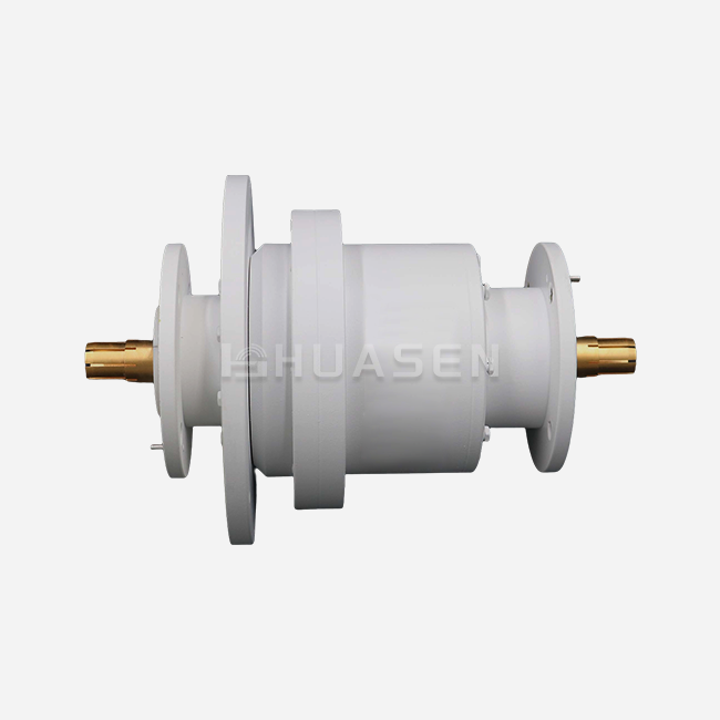
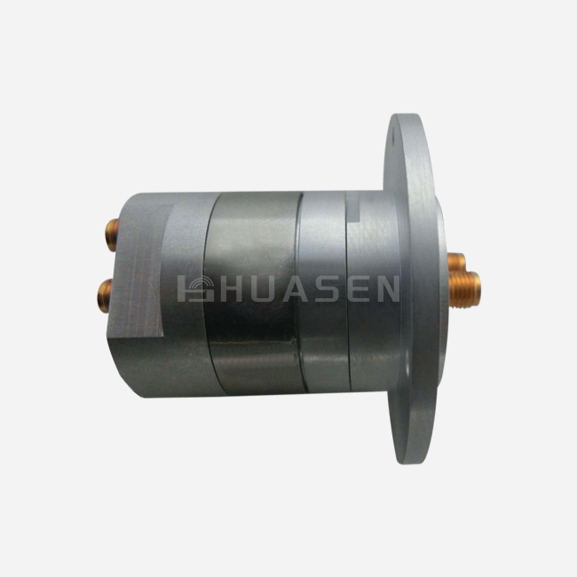
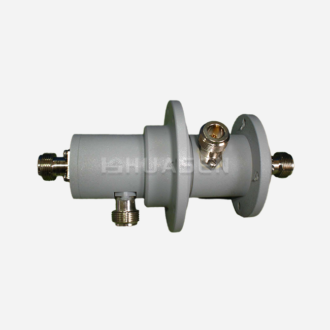
Waveguide transitions are the hidden stars of microwave communication systems. They keep the signal's integrity while connecting different types of transmission media. These carefully made parts solve a basic problem: how to connect RF energy between square waveguides, round waveguides, coaxial wires, and microstrip lines with little loss and reflection. A waveguide transition, when designed correctly, keeps impedance matching across frequency bands, lowers voltage standing wave ratio (VSWR), and stops mode conversion, which hurts link performance. Engineers working on 5G infrastructure, satellite ground stations, and radar systems know that a 0.2 dB drop in insertion loss can make a big difference in how much power they use and how far they can operate.
Understanding Waveguide Transitions and Their Impact on Microwave Links
The physical rules that govern waveguide transitions are based on changing impedance and keeping the electromagnetic field steady. When radio waves move from one type of transmission medium to another, like from a WR-112 rectangular waveguide to a coaxial connection, sudden changes in cross-sectional shape make breaks that send energy back to the source.
The Physics Behind Signal Coupling
Modern waveguide transitions use stepped or tapered geometries to change the electromagnetic field pattern slowly over time. It's possible for a tapered transition to cover more wavelengths, which would let the TE₁₀ mode in a rectangular guide easily change into the TEM mode in coaxial cable. This gradual change keeps phase coherence while reducing reflection to a minimum. Computational electromagnetic modeling helps engineers at research institutions and equipment makers find the best geometries by balancing the need for bandwidth with physical length limits.
Material Selection and Power Handling
Whether you choose oxygen-free copper (OFHC), brass, or aluminum alloys has a big effect on how well they conduct electricity and how long they last mechanically. Copper transitions are better at conducting electricity, which means that insertion loss is less than 0.15 dB in many X-band uses. To stay within weight limits for UAVs and spacecraft, aerospace integrators often choose aluminum variants, even if it means losing a little more mass. Both silver plating and gold plating are important for different reasons. Silver plating stops oxidation over decades of use, while gold plating is best for specialized lab instruments that need very stable calibration references.
High-power uses put extra limits on what can be done. Air-dielectric waveguide-to-waveguide Transitions can usually handle kilowatts of continuous power, with thermal dissipation and multipaction limits being the main things that limit them. The dielectric breakdown voltage and current-carrying capacity of the coaxial connector set stricter limits for coaxial-to-waveguide adapters.
Identifying and Overcoming Waveguides Transition Performance Bottlenecks
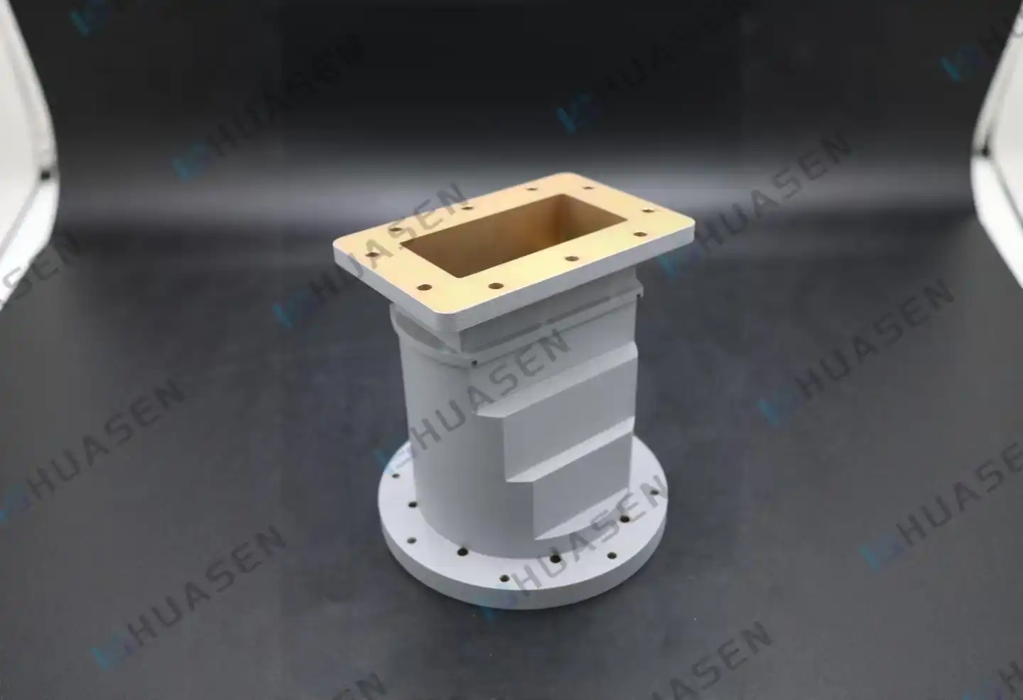
When microwave links lose performance, it's often because of mistakes made in the waveguide transition design. A phone company that was improving a 5G backhaul system found that old transitions caused 0.8 dB of extra loss across Ka-band frequencies, which directly cut down on cell site coverage. An investigation into the root cause showed that there were impedance mismatches at the flange interfaces and parasitic mode excitation within the transition body.
Addressing Impedance Mismatch
VSWR below 1.15:1 is the standard for precise waveguide transition transitions in the industry, but it takes advanced matching techniques to reach this level of accuracy across multiple octave bandwidths. Chebyshev multi-section transformers shorten the length of a wire by using quarter-wave steps and calculated impedance ratios. In exchange for wider bandwidth, binomial systems have steeper roll-off properties. When engineers look at a supplier's specs, they should ask for full two-port S-parameter data across all operational temperatures, not just VSWR numbers at room temperature.
| Performance Metric | Standard Grade | Precision Grade | Impact on System |
|---|---|---|---|
| VSWR | 1.25:1 | 1.10:1 | Return loss changes how stable an emitter is. |
| Insertion Loss | 0.2 to 0.5 dB | <0.15 dB | Link gap goes down as loss builds up. |
| Frequency Range | One band | Multiple octaves | Less inventory and more design options |
| Power Handling | <100W average | >1kW top | Finds out if the application is suitable |
Real-World Case Studies
A defence contractor working on airborne radar systems had problems with the integrity of the signals. These problems were traced to waveguide twist transitions that connected the gimbal assembly to fixed transmit/receive modules. Due to mechanical flexing during vibration, the original design had resonance peaks at certain scan angles. By redesigning the transition with stress-relief bellows and better internal shape, unwanted modes were removed. This made the angle-dependent gain flatness 1.2 dB better. In demanding situations, this example shows how mechanical and RF design issues can come together.
Millimetre-wave communication systems that work above 60 GHz have their own set of problems. At these frequencies, manufacturing tolerances are very important—surface roughness greater than 32 microinches makes skin-effect losses measurable. One company that makes satellite terminals cuts W-band transition losses by 0.3 dB by electropolishing the inside of the panels and using stricter CMM inspection rules while the panels are being made.
Comparing Waveguide Transition Solutions for Optimal Procurement Decisions
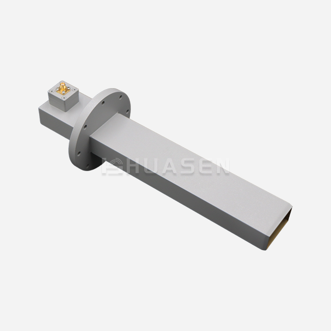
There are so many types of waveguide transitions that procurement managers can make, and each one works best in a different situation. The easiest type is rectangular-to-rectangular changes between standard waveguide sizes (WR-340 to WR-284, for example). These are usually required when putting together equipment from different frequency bands. Coaxial-to-waveguide launchers are used in test and measurement tasks where vector network analysers with coaxial ports need to describe waveguide parts. Compact millimetre-wave transceivers for 5G small cells are made possible by microstrip-to-waveguide transitions, which merge into printed circuit boards.
Material Trade-Offs in Production Environments
When every gram counts, aircraft use aluminium metal 6061-T6 more than any other type. Its thermal expansion coefficient is very close to that of mounting structures. This means that it reduces mechanical stress when the temperature changes from -55°C to +125°C. Brass transitions are easy to machine for special samples and small production runs, but they need to be carefully plated to keep them from dezincifying in salty environments. OFHC copper is still the best material for stationary ground infrastructure like base stations, combining networks and satellite earth stations, because it is highly conductive and requires less cooling, which directly lowers operating costs.
| Material | Conductivity (% IACS) | Density (g/cm³) | Typical Application | Cost Factor |
|---|---|---|---|---|
| OFHC Copper | 101 | 8.96 | Standards for lab calibration | High |
| Brass (C36000) | 28 | 8.53 | Transitions for general use | Medium |
| Aluminum 6061-T6 | 43 | 2.70 | Radar in the air and a satellite payload | Low |
Evaluating Supplier Capabilities
Well-known brands stand out by having strict quality control systems and the ability to test their products. Suppliers who offer full S-parameter sweeps from vector network analysers that have been certified according to NIST standards show that they are dedicated to performance that can be measured. Long-term reliability claims are backed up by tests that follow MIL-STD-810 thermal cycling and salt spray exposure (ASTM B117). For flange flatness, procurement professionals should ask for coordinate measuring machine (CMM) inspection reports; deviations greater than ±0.02 mm lead to RF leakage and poor repeatability when connectors are mated.
Procurement Strategies for Efficient Waveguide Transition Acquisition
A good buying process strikes a mix between technical needs and practical business issues. A company that is putting together a nationwide 5G network needs a lot of transitions that are all the same and have consistent prices and delivery times. A research lab, on the other hand, might need a few custom units with unusual frequency coverage and special flanges.
Stock Versus Custom Fabrication
Standard catalogue items for common waveguide sizes (WR-90, WR-62, and WR-42) and frequencies usually ship within two weeks from distributors who keep stock. These ready-made options work well for projects with standard needs and limited time frames. Lead times can be eight weeks or longer for custom transitions that deal with unusual frequency splits, non-standard flange combinations, or harsh environmental requirements. This is because the tools need to be set up and tested to make sure they work properly.
Buyers who want to save money might be able to get better unit prices by combining their orders or agreeing to longer delivery windows, which give makers more time to make the best batches of circular waveguide transition products. On the other hand, suppliers who offer low minimum-order-quantity (MOQ) custom manufacturing with technical help during the design iteration phase are good for prototyping projects.
Technical Specification Alignment
By clearly defining operational parameters, you can avoid expensive problems that happen when bought parts don't work with what the system needs. The most important requirements are the operating frequency range, paying special attention to the band edges where VSWR may decrease, the average and peak power handling requirements that take pulsed operation in radar applications into account, and the environmental exposure that includes temperature extremes, humidity, and shock/vibration profiles according to MIL-STD-810 or an equivalent commercial standard.
Interface compatibility is more than just frequency—mechanical details like mounting orientation, bolt hole patterns, and flange type (UG, CPR, or UBR) have a big effect on how hard it is to integrate. During the quotation phase, asking for 3D CAD models in STEP or IGES format helps find interference problems before the fabrication process starts.
Future Trends and Innovations in Waveguide Transition Technology
To meet the needs of 5G/6G wireless infrastructure, satellite mega-constellations, and self-driving car radar, the microwave components business keeps changing. Waveguide transition technology will change in the future because of a number of trends.
Advanced Materials and Manufacturing
It is possible to make complex internal shapes with additive manufacturing (3D printing) that isn't possible with standard machining. Researchers have shown that direct metal laser sintering (DMLS) can make multi-section Chebyshev transitions with built-in cooling channels. These units have the same performance as traditionally machined units but are 30% lighter. More people will use the technology in low-volume, high-performance settings as it gets better and the surface finish gets better.
Low-loss dielectric materials are still getting better, especially for substrate-integrated waveguide (SIW) transitions that combine the advantages of planar circuit integration with waveguide power handling. These mixed methods help the trend toward smaller sizes that is driving millimetre-wave 5G radio heads and phased-array antennas.
System Integration and Smart Components
In the future, circular waveguide transition transitions might have built-in sensors that check the VSWR and temperature in real time and send the information to systems that plan for preventative repair. This feature comes in handy for installations that are far away, like communication links for offshore wind farms or satellite gateways in the polar regions, where field service costs a lot of money each visit. Finding trends of wear and tear early on lets replacements be planned before a major failure stops operations.
Conclusion
Waveguide transitions are important points where the efficiency of a radio link can be improved or lost. Engineers and purchasing managers can make better decisions when balancing technical needs with budget and time constraints when they know about their design principles, performance characteristics, and procurement strategies. Understanding how insertion loss, VSWR, and material choices affect system performance and running costs is important whether you are putting together business 5G base stations or getting parts ready for space flight. Waveguide transition technology is still an active field that needs careful attention from anyone designing microwave transmission systems because it is always changing to have higher frequencies, wider bandwidths, and smaller form factors.
FAQ
1. What distinguishes tapered transitions from stepped designs?
Tapered transitions use linear, exponential, or optimised curves to make small changes in dimensions over a number of wavelengths in order to achieve very low VSWR across a wide range of bandwidths. Stepped transitions use quarter-wave transformer sections with clear impedance jumps. This shortens the physical length but makes the bandwidth a little less wide. When you need to pack something small, stepped designs work best, but for maximum accuracy, measurement standards need tapered designs.
2. How does surface finish affect high-frequency performance?
When microwaves and millimetre waves are used, current only flows a few skin depths below the surface of the conductor. Rough cutting lines raise the effective resistance, which causes more insertion loss and heat when the power is turned up high. Surface roughness can be lowered below 32 microinches by electropolishing or precision diamond turning. This keeps the design's performance. Copper rust adds lossy dielectric layers that hurt performance over time. Silver finishing stops this from happening.
3. Can waveguide transitions handle full kilowatt power levels safely?
Kilowatt continuous and megawatt peak power are regularly managed by air-dielectric waveguide-to-waveguide transitions, with breakdown voltage and thermal dissipation serving as limits. The coaxial connector's dielectric and current capacity put stricter limits on coaxial-to-waveguide adapters. The average power of a coaxial connector is usually hundreds of watts. Always compare power rates to your actual job cycle, keeping in mind that altitude and temperature can change the ratings.
Partner with Huasen Microwave for Superior Waveguide Transition Solutions
The quality of the Waveguide Transition has a direct effect on how well and reliably your radio system works. Huasen Microwave Technology is a leading Waveguide Transition manufacturer that has been in business since 1993. They have more than thirty years of experience in RF engineering and can make precise parts. Our range of products covers frequencies from X-band to W-band, and all of them have VSWR specifications below 1.15:1 and insertion losses below 0.2 dB. Our engineering team can help you with design, S-parameter verification, and thermal cycling proof according to MIL-STD standards, whether you need standard WR-series transitions or custom configurations for tough aerospace uses. You can talk to our expert sales team at sales@huasenmicrowave.com about your needs, ask for samples, or get a quote. We help procurement professionals around the world by offering competitive prices, flexible minimum order quantities, and reliable delivery times.
References
1. Pozar, David M. Microwave Engineering, 4th Edition. Hoboken: Wiley, 2011.
2. Saad, Theodore S. The Microwave Engineer's Handbook and Buyer's Guide, Volume 2. Horizon House Publications, 1988.
3. Balanis, Constantine A. Advanced Engineering Electromagnetics, 2nd Edition. New York: Wiley, 2012.
4. MIL-DTL-85/3C: Waveguide, Rigid, Rectangular (Millimeter Wave), General Specification For. Department of Defense, 2015.
5. IEEE Standard 1785.2-2016. IEEE Standard for Rectangular Metallic Waveguides and Their Interfaces for Frequencies of 110 GHz and Above—Part 2: Waveguide Interfaces. Institute of Electrical and Electronics Engineers, 2016.
6. Matthaei, George L., Leo Young, and E.M.T. Jones. Microwave Filters, Impedance-Matching Networks, and Coupling Structures. Norwood: Artech House, 1980.
Send Inquiry