What Factors Affect Waveguide Tube Performance and Signal Loss?






2026-07-28 10:40:30
Waveguide tube performance and signal loss are primarily influenced by material conductivity, dimensional precision, surface finish quality, installation alignment, and environmental conditions. The choice of conductor materials like oxygen-free copper or aluminum alloys directly impacts attenuation rates, while internal geometry determines cutoff frequency and bandwidth. Surface roughness increases resistive losses, and poor flange connections or bending radius violations introduce reflection and radiation losses. Temperature fluctuations, moisture ingress, and mechanical stress further degrade transmission efficiency, making careful design and installation critical for maintaining optimal performance in high-frequency microwave applications.
Understanding Waveguide Tube Performance Fundamentals
Waveguide technology is an important part of modern microwave engineering because it makes signal transfer safe in radar sites, telecommunications networks, and satellite ground stations. Unlike regular coaxial cables, which have trouble with dielectric losses above 1 GHz, these hollow metal structures guide electromagnetic energy through air or an inert gas, which makes attenuation much less noticeable in the Super High Frequency and Extremely High Frequency bands. The basic idea behind how a waveguide tube works is that electromagnetic fields move through holes of exact sizes. The main mode, which is usually TE10 in rectangular waveguides, carries energy with little spreading out.
Types and Frequency Ranges
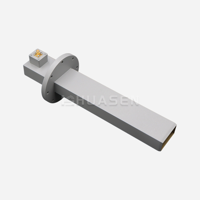
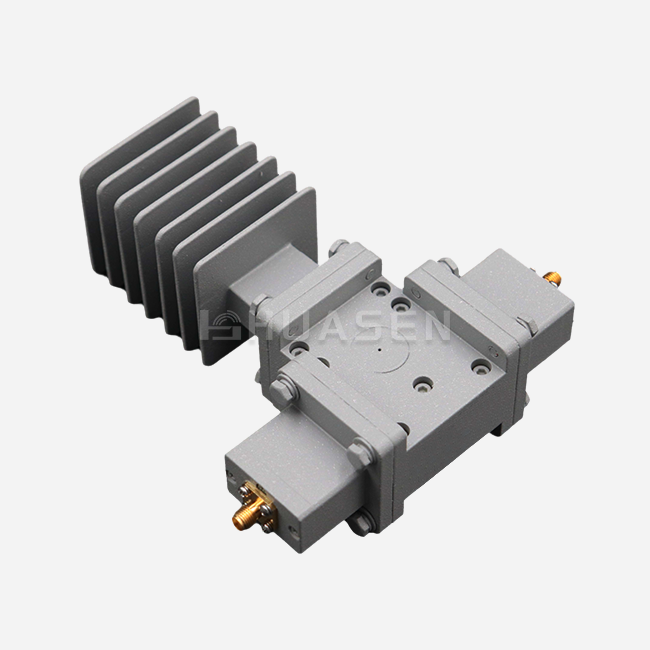
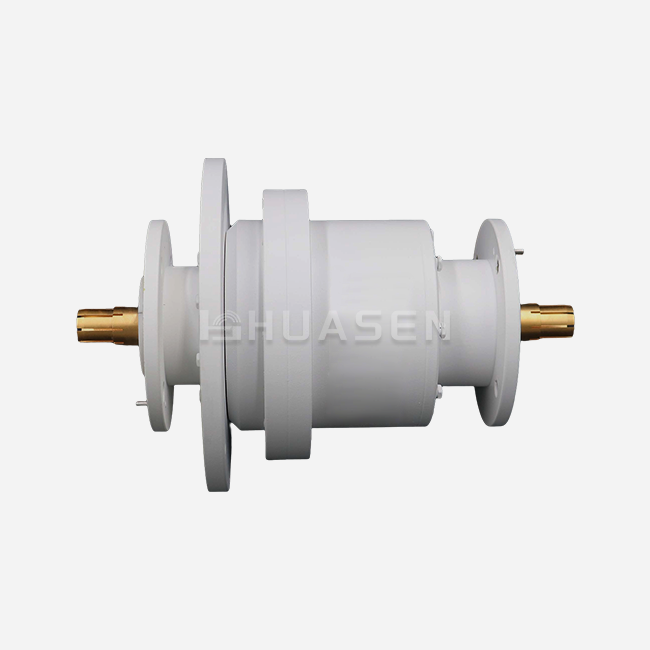
The business world knows of a number of geometric arrangements that work best for different types of operations. Rectangular waveguides are most common in business and military settings because they are easy to make and have known propagation properties. For example, circular versions are used in rotating antenna assemblies that need to rotate the polarization. Rigid units have better electrical performance because their dimensions are always the same. Flexible waveguides, on the other hand, can be used in setups that need to move mechanically, but they have a small performance loss.
Standard rectangular waveguides from Huasen Microwaves come in new single-ridge and dual-ridge configurations that get around the bandwidth problems that come with older designs. Dual-ridge architectures make the useful bandwidth much bigger while dropping the cutoff frequencies. This lets designers make smaller systems that work just as well. Single-ridge versions are the best because they balance the need for electrical properties with their small size, making them perfect for installations with limited space in base station front ends and small radar modules.
Industry Applications Across Sectors
These transmission lines are used by radar altimeters, weather monitoring arrays, and satellite communication packages. Because they are light, they are made of aluminum and have protective coatings. They are used in base station duplexers and high-power combiners for 5G millimeter-wave backhaul lines in the telecommunications system. Electronic warfare pods, missile guidance systems, and shipboard phased array radars that work in harsh environments are all examples of defense applications. For network analyzer calibration and antenna pattern readings that need traceable reference standards, testing labs rely on precise waveguides.
When it comes to maritime communication, the problems are unique. Corrosion from saltwater and mechanical vibration mean that designs need to be tough and have special surface treatments. Broadcasting stations use these parts in high-power broadcast outputs that need to be able to handle pulses at the megawatt level. In food processing and compound curing, industrial microwave heating systems easily move continuous wave energy through waveguide runs that connect magnetrons to applicator holes with a waveguide tube.
Core Factors Affecting Waveguide Tube Performance and Signal Loss
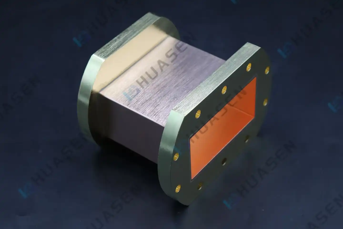
The efficiency qualities of a waveguide tube are based on the material that is used. Conduction losses are directly related to the electrical conductivity of the wall material. Copper that is oxygen-free and has a high conductivity has the lowest attenuation figures. The aluminum alloy 6061-T6 is a good choice for airborne platforms because it saves weight, but it needs to be a little bigger to have the same loss performance. Surface treatments are very important. For example, silver plating lowers skin effect resistance while stopping rust. Gold plating, on the other hand, is more stable over time in acidic environments, even though it costs more at first.
Material Properties and Signal Attenuation
Internal surface roughness causes tiny changes in the path of the current, which raises the effective resistance above what would be expected from theory. To keep surface finishes below 32 micrometers Ra during manufacturing, too much attenuation multiplication at millimeter-wave frequencies must be avoided. Plating thickness needs to be carefully managed; not enough covering lets base oxidation through, and too much thickness raises the cost of production without improving performance. Chemical passivation processes keep aluminum surfaces from corroding when they come into contact with metals that are not the same in flange assemblies.
The dielectric properties of any pressure windows or internal support structures have a direct effect on the integrity of the signal. PTFE materials are often used to make bendable waveguides, but their loss tangents change with temperature, which means they don't work as well when the temperature changes. Air-dielectric stiff guides get rid of this problem, but they need precise mechanical support to keep the dimensions from shifting. When used in space, where volatile compounds can stick to cold surfaces and change their electrical properties over the course of a journey, outgassing qualities become very important.
Dimensional Design and Frequency Compatibility
Waveguide theory sets the cutoff frequencies that determine the working bandwidth based on the physical measurements. The dominant mode only moves when the operating frequency goes above the cutoff threshold, which is set by the wide wall dimension in rectangular guides. Standard WR-series names list the dimensions that work best for certain frequency bands. The recommended operating ranges are usually between 1.25 and 1.90 times the cutoff frequency to find the best balance between loss performance and higher-order mode suppression.
| Waveguide Type | Cutoff Frequency (GHz) | Recommended Band (GHz) | Internal Dimensions (inches) |
|---|---|---|---|
| WR-90 | 6.56 | 8.2 - 12.4 | 0.900 × 0.400 |
| WR-62 | 9.49 | 12.4 - 18.0 | 0.622 × 0.311 |
| WR-42 | 14.05 | 18.0 - 26.5 | 0.420 × 0.170 |
| Single-Ridge WR-137 | 4.30 | 5.65 - 8.20 | Custom profile |
The voltage standing wave ratio and insertion loss are both affected by the limits of the dimensions. Manufacturing errors bigger than ±0.001 inches cause impedance gaps that cause echoes, which is a big problem for systems that use precise measurements. To keep hybrid assemblies from losing their shape as the temperature range changes, the thermal expansion coefficients of the different materials must match. The width of the pressure window affects both its mechanical strength and its electrical length, so it needs to be optimized for use at high altitudes or under pressure.
Installation and Environmental Influences
Misalignments of the flanges as little as 0.005 inches can cause air holes that let energy escape and cause reflected loss. When it comes to fixing hardware torque specs, it's important to follow what the maker says—not enough clamping force can cause interface degradation, and too much torque can deform gasket materials or distort waveguide apertures. When choosing a gasket material, it's important to think about both how well it seals and how well it conducts electricity. For example, silver-plated beryllium copper fingerstock is the best material for RF contact in reuse interfaces.
Extreme temperatures change the qualities of a material and its ability to keep its shape. Aluminum structures increase 13 ppm for every degree Celsius, which could make flanges not line up correctly in waveguide tube setups that are exposed to large temperature changes. Moisture getting in through poor sealing leads to corrosion, which raises the surface resistance and eventually leads to catastrophic failure. When there is vibration, there needs to be enough space between the mechanical supports to stop resonant frequency excitation, which could cause fatigue cracks at stress concentration points.
Comparing Waveguide Tubes with Other Transmission Media in Performance Terms
To choose the right gearbox technology, you have to weigh a number of efficiency factors against the needs of the application. Waveguide tubes work great in high-frequency, high-power situations where coaxial alternatives lose too much signal or get too hot. When procurement managers understand these trade-offs, they can use performance data instead of common ideas to support the choice of technology.
Performance Advantages Over Coaxial Cables
The biggest difference in efficiency is the amount of power it can handle. It is normal for rigid rectangular waveguides to handle kilowatt levels of continuous waves and megawatt levels of peak pulse power without the dielectric breaking down. When the power level is two orders of magnitude lower, semi-rigid coaxial wires with similar frequencies experience dielectric heating and eventually fail. This feature is very important in radar transmitters and high-power industrial heating situations where coaxial technology just won't work.
The way insertion loss works strongly supports waveguides above 10 GHz. At 10 GHz, a WR-90 guide has about 0.03 dB/meter of loss, while a similar 0.141-inch semi-rigid coaxial cable has 1.2 dB/meter of loss, which is 40 times more. This difference gets worse in setups that need transmission runs longer than a few meters. This is because the accumulated coaxial loss means that more amplification is needed, which adds cost and complexity and lowers dependability.
| Parameter | Waveguide (WR-90) | Coaxial (0.141" Semi-Rigid) | Fiber Optic (Single-Mode) |
|---|---|---|---|
| Frequency Range | 8.2 - 12.4 GHz | DC - 18 GHz | 193 - 196 THz (optical) |
| Insertion Loss | 0.03 dB/m @ 10 GHz | 1.2 dB/m @ 10 GHz | 0.0002 dB/m @ 1550 nm |
| Power Handling | >100 kW CW | 50 W CW | N/A (intensity only) |
| Environmental Sealing | Excellent (rigid) | Good (hermetic versions) | Requires protection |
Trade-offs with Optical Fiber Technology
In communications, optical fibres offer the best bandwidth-to-distance ratios and almost no loss. However, they can't directly handle RF energy without photonic conversion. Fibre-based system designs need to include RF-to-optical and optical-to-RF conversions, which add delay, lower noise figures, and more failure causes. When RF is sent directly through waveguides, these changes are not needed, so fibre's wider bandwidth is not an advantage.
Cost structures are very different between the two types of systems. Fibre systems need expensive electro-optical parts at each end, while waveguide systems just need simple flanges to connect to the transmission line. Waveguides are more cost-effective for short-haul applications, while fibre's low loss makes it useful for long-distance communications, even though it costs more to convert signals. Concerns about electromagnetic compatibility go away with optical separation, but many systems need to keep the RF signal intact for phase-coherent uses where photonic conversion causes too much distortion.
Selection Criteria for Procurement Decisions
The main selection filter is set by the operating frequency. Even though they lose more signal at higher frequencies, coaxial lines are more flexible and cost-effective below 3 GHz. Between 3 and 40 GHz, waveguides are used for long-run and high-power installs, while coaxial solutions are used for short connections where freedom is worth the extra loss. As coaxial losses get too high for millimetre-wave applications above 40 GHz, waveguide technology becomes more and more appealing.
Some technologies are quickly ruled out because they need a lot of power. Waveguide construction is needed for transmitter outputs greater than 100 watts continuous, no matter the frequency or how complicated the installation is. Receiver front ends that deal with microwatt levels can handle cable loss as long as the total runs are short. Peak power specs are also important—pulse radars that send out megawatt bursts need waveguide construction with the right pressure ratings and multipactor reduction features.
The environment affects the choice of technology by affecting factors like dependability and upkeep. When used outside, where they are exposed to extreme temperatures, rain, and UV rays, sealed rigid waveguide tubes are better than coaxial options that need regular connector maintenance. Pressurised waveguide runs in aeroplane gas systems get rid of the arcing that happens at high altitudes and stops coaxial cables from working well above 40,000 feet. In harsh industrial environments, protected coatings are needed. These coatings are easy to put on the outside of waveguides but hard to put on the covers of coaxial cables.
Conclusion
Optimising waveguide tube performance requires taking into account the qualities of the material, the accuracy of the measurements, the installation method, and the surroundings. When you choose the right material and treat the surface properly, you can lower the loss of conduction. Controlling the dimensions of the part also lowers the loss of reflection and radiation. Maintenance on the bend radius and high-quality flange connections help keep the signal's integrity across system setups. Comparative research shows that waveguides are clearly better than coaxial options in high-frequency, high-power uses, even though they cost more at first. To be successful in procurement, you need to look at a supplier's skills beyond what's listed in a catalogue. You should focus on their manufacturing knowledge, ability to make changes, and possibility for a long-term relationship.
FAQ
1. What frequency range do standard waveguides cover?
Standard rectangular waveguides can handle frequencies from about 1 GHz to 220 GHz, with smaller diameters as the frequency goes up. The WR-series numbering method sets the best dimensions for each band. For example, WR-650 is best for 1.12 to 1.70 GHz uses, and WR-10 is best for 75 to 110 GHz ones. Each standard size works well over a bandwidth ratio of about 1.5:1. The suggested working ranges stay away from cutoff frequency proximity and higher-order mode regions. When a system needs a single component to cover a wider area, custom ridge-loaded designs raise bandwidth ratios above 2:1.
2. How does temperature affect waveguide performance?
Temperature changes the size and properties of materials, which in turn changes the way waveguides work. Aluminium structures expand by about 23 ppm/°C, which could make the flanges not line up correctly in long runs where the temperature changes. Copper's electrical conductivity drops by about 0.4% per degree Celsius, which makes absorption worse when temperatures rise. Thermal cycling causes mechanical stress at the points where different materials meet, which could weaken the flange contact pressure over time. The specifications should list the working temperature ranges and the performance limits that go with them. The installation designs should account for thermal expansion by using the right support spacing and, if necessary, flexible sections.
3. Can waveguides handle both transmit and receive signals?
Waveguides can easily handle both sending and receiving at the same time in a number of different configurations. Using resonant cavity filters built into common waveguide ports, diplexers split frequency bands so that antenna links can be shared. When frequency separation isn't enough for filter discrimination, circulator-based duplexers separate the send and receive lines. Dual-polarisation devices use fields with opposite directions that move through the same structure without interfering with each other. Power handling and isolation needs determine the best way to apply things. For example, high-power emitters might need their own waveguide runs to keep receivers from losing their sensitivity, even though this makes the system more complicated.
Partner with Huasen Microwave for Superior Waveguide Solutions
Manufacturers of radar systems and telecommunications infrastructure need Waveguide tube suppliers they can rely on to provide consistent performance in harsh operating settings. Huasen Microwave has been working in RF engineering for 30 years and has advanced production skills that allow them to make standard and custom waveguide solutions that meet strict military and business standards. Our single-ridge and dual-ridge rectangular waveguides meet the needs for bandwidth expansion while keeping the small sizes needed for modern base stations and satellite communication systems.
Internationally recognised quality assurance processes make sure that every part meets the published specifications before it is shipped. Technical support teams offer electromagnetic modelling validation and sample assessment tools to help with design during the system development stages. Customisation services can meet special needs for regularity, interface, and environmental factors without charging too much for extra time. Email our engineering team at sales@huasenmicrowave.com to talk about your specific application needs and get detailed technical suggestions that are best for your performance and budget.
References
1. Pozar, David M. Microwave Engineering, 4th Edition. Wiley, 2011. Chapter 3: Transmission Lines and Waveguides.
2. Saad, Theodore S. Microwave Engineers' Handbook, Volume 1. Artech House Publishers, 1971. Section on Rectangular Waveguide Design.
3. Marcuvitz, Nathan. Waveguide Handbook. MIT Radiation Laboratory Series Volume 10. McGraw-Hill, 1951.
4. IEEE Standard 149-1979. IEEE Standard Test Procedures for Antennas. Institute of Electrical and Electronics Engineers, 1979.
5. Balanis, Constantine A. Advanced Engineering Electromagnetics, 2nd Edition. Wiley, 2012. Chapter 9: Rectangular Waveguides.
6. Military Specification MIL-DTL-85/3C. Waveguide, Rigid, Rectangular, Aluminium, Department of Defence, 2008.
Send Inquiry