
How to Optimize Circular Waveguide Termination for Power Loads?






2026-01-26 20:47:35
When engineers face excessive signal reflections and power handling failures in high-frequency RF systems, the root cause often lies in poorly optimized Circular Waveguide Termination. Achieving optimal performance requires carefully balancing impedance matching, thermal management, and absorber material selection to handle power loads efficiently while maintaining minimal VSWR across wide frequency ranges. This comprehensive guide reveals proven optimization strategies that enable your system to absorb electromagnetic energy reliably, prevent generator damage from reflected power, and ensure measurement accuracy in experimental setups.
Understanding Circular Waveguide Termination Fundamentals
Circular Waveguide Termination represents a critical passive component designed to absorb microwave and millimeter-wave energy traveling through circular waveguide systems without creating significant reflections. Unlike rectangular waveguide terminations, circular variants must accommodate multiple electromagnetic modes, particularly the dominant TE11 mode and TM01 mode, which propagate differently within the cylindrical geometry. The fundamental challenge engineers encounter involves creating an impedance transition that gradually converts the waveguide's characteristic impedance to the load impedance, thereby minimizing return loss and maximizing power absorption efficiency.
The physics governing Circular Waveguide Termination operation centers on progressive energy dissipation through resistive and dielectric materials. When electromagnetic waves enter the termination structure, they encounter carefully engineered absorber materials that convert RF energy into heat through molecular friction and conductivity losses. The conical or tapered geometry commonly employed in high-performance terminations serves a dual purpose by gradually changing the impedance profile and distributing power absorption across a larger volume, which enhances thermal management and reduces hotspot formation. This design approach proves particularly effective for power loads ranging from several watts to multiple kilowatts, depending on the cooling methodology and absorber material properties.
Manufacturing precision significantly impacts Circular Waveguide Termination performance characteristics. The concentricity between the waveguide body and internal absorber structure must be maintained within tight tolerances to ensure uniform field distribution and prevent mode conversion that could compromise VSWR specifications. Surface finish quality on flange interfaces directly affects connection repeatability and long-term reliability, especially in systems experiencing thermal cycling or mechanical vibration. Advanced manufacturers employ precision CNC machining, coordinate measuring machines, and specialized waveguide processing techniques to achieve the dimensional accuracy required for components operating at millimeter-wave frequencies extending beyond 100 GHz.
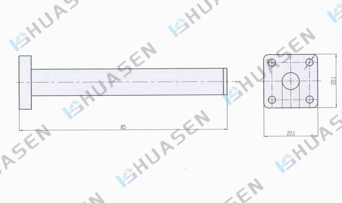
Key Design Parameters for Power Load Optimization
Optimizing Circular Waveguide Termination for power handling demands careful attention to several interrelated design parameters that collectively determine overall system performance. The voltage standing wave ratio constitutes the primary electrical specification, with values of 1.15 or lower considered excellent for precision measurement applications. Achieving such performance across multi-octave frequency ranges requires sophisticated electromagnetic modeling using finite element analysis tools that can simulate field distributions, reflection coefficients, and thermal gradients under various operating conditions. The absorber taper angle emerges as a critical geometric parameter, with longer, more gradual tapers generally providing superior impedance matching but requiring additional space within system architectures.
Thermal design considerations become paramount when addressing continuous wave power loads exceeding tens of watts. The power density within absorber materials must remain below critical thresholds that could trigger thermal runaway, material degradation, or permanent damage to the Circular Waveguide Termination assembly. Engineers typically calculate maximum allowable power dissipation based on absorber material properties, including thermal conductivity, specific heat capacity, and maximum operating temperature. For moderate power applications, passive convection cooling through finned heat sinks attached to the waveguide body often suffices, while high-power systems may require forced air cooling or even liquid cooling circuits integrated into the termination housing. The thermal resistance from the absorber core to the external heat sink determines steady-state temperature rise and ultimately limits continuous power handling capability.
Material selection for both the waveguide body and internal absorber elements significantly influences Circular Waveguide Termination performance and longevity. Gold-plated brass construction offers excellent corrosion resistance and superior RF performance through low surface resistance, making it ideal for laboratory environments and precision instrumentation applications. Aluminum waveguide bodies provide weight savings critical for airborne and space-based systems, though special attention to surface treatment prevents oxidation that degrades electrical performance over time. The absorber material itself must exhibit stable electrical properties across wide temperature ranges, minimal outgassing for vacuum applications, and compatibility with environmental exposure requirements. Carbonyl iron compounds, silicon carbide ceramics, and specialized polymer-based composites each offer distinct advantages depending on frequency range, power level, and environmental factors specific to the application.
Absorber Material Configuration
The geometric arrangement of absorber materials within the Circular Waveguide Termination structure profoundly affects both electrical and thermal performance. Traditional conical absorber designs feature a gradual taper that transitions from zero cross-section at the insertion point to maximum diameter at the termination end, creating an impedance transformation that minimizes reflections. Advanced configurations employ multi-stage absorber geometries, combining wedge-shaped elements near the entrance with cylindrical or conical sections deeper within the structure to optimize mode absorption characteristics. This approach proves particularly effective when the termination must handle multiple propagating modes simultaneously, as each geometric section can be optimized for specific mode patterns.
Research into waveguide termination optimization reveals that resistive disc placement within the absorber assembly can fine-tune frequency response and enhance return loss performance at critical operating frequencies. Engineers position dielectric spacers between absorber sections to create impedance steps that broaden the effective bandwidth while maintaining excellent VSWR characteristics. The bulk absorber material density and composition can be varied along the longitudinal axis, creating a gradual transition in electrical properties that further reduces impedance discontinuities. These sophisticated design techniques enable modern Circular Waveguide Termination products to achieve VSWR specifications below 1.10 across frequency ranges spanning multiple waveguide bands.
Advanced Thermal Management Strategies
Addressing thermal challenges in high-power Circular Waveguide Termination applications requires comprehensive understanding of heat generation mechanisms and transfer pathways. The volumetric power dissipation within absorber materials creates temperature gradients that must be carefully managed to prevent localized overheating. Finite element thermal analysis helps designers predict temperature distributions under various power loading scenarios, identifying potential hot spots that might limit overall power handling capacity. The thermal conductivity path from the absorber core through the waveguide wall to the external environment determines the effectiveness of heat removal, with attention required to minimize thermal interface resistances at material boundaries.
Passive cooling approaches for moderate power Circular Waveguide Termination assemblies typically incorporate extended surface heat sinks that increase convective heat transfer to surrounding air. The fin geometry, including height, thickness, and spacing, must be optimized based on natural or forced convection conditions expected during operation. Surface treatments such as anodizing or black oxide coating can enhance radiative heat transfer, providing additional cooling benefit particularly in vacuum environments where convection proves ineffective. For applications requiring enhanced cooling performance without active systems, heat pipe technology can transport thermal energy from the termination assembly to remote heat sink locations, effectively spreading the thermal load across larger surface areas.
Active cooling systems become necessary for Circular Waveguide Termination applications involving continuous power levels exceeding several hundred watts or pulsed applications with peak powers in the kilowatt range. Forced air cooling using dedicated fans or blowers provides cost-effective thermal management, with airflow directed across finned heat sink surfaces attached to the waveguide body. Careful attention to air inlet and outlet positioning ensures efficient heat removal without creating turbulence or noise issues. Liquid cooling circuits, while more complex and expensive, enable substantially higher power handling through superior heat transfer coefficients compared to air cooling. Water or water-glycol mixtures flow through channels machined into the waveguide housing or attached cooling jackets, removing heat with minimal temperature rise in the Circular Waveguide Termination assembly itself.
Thermal Performance Monitoring
Implementing temperature monitoring capability within high-power Circular Waveguide Termination assemblies provides valuable operational data and enhances system safety. Thermocouples or resistance temperature detectors embedded near critical absorber regions enable real-time temperature tracking, allowing control systems to adjust power levels or activate additional cooling as needed to maintain safe operating conditions. Temperature data logged during testing and operation helps validate thermal models and provides early warning of potential degradation or failure modes. Some advanced termination designs incorporate multiple temperature sensors distributed throughout the assembly, creating a thermal map that reveals detailed information about heat distribution and cooling effectiveness.
Measurement and Verification Techniques
Validating Circular Waveguide Termination performance requires sophisticated measurement techniques that accurately characterize electrical and thermal behavior under realistic operating conditions. Vector network analyzer measurements provide detailed S-parameter data across the full operating frequency range, revealing reflection coefficient magnitude and phase information essential for assessing impedance matching quality. The measurement setup must account for systematic errors introduced by cables, adapters, and waveguide flanges through careful calibration procedures that reference the measurement plane precisely to the termination input interface. Time-domain reflectometry techniques can supplement frequency-domain measurements, identifying discrete impedance discontinuities within the termination structure that contribute to VSWR degradation.
Power handling verification requires controlled testing under conditions that simulate actual application environments without risking equipment damage. Initial low-power testing confirms basic electrical functionality before gradually increasing power levels while monitoring termination temperature rise and reflected power. Thermal imaging cameras provide valuable visualization of temperature distribution across the termination assembly, identifying unexpected hot spots that might indicate design flaws or manufacturing defects. Long-duration power testing at rated conditions validates thermal stability and reveals potential degradation mechanisms that could affect long-term reliability. For Circular Waveguide Termination products intended for extreme environments, additional testing under temperature cycling, humidity exposure, and vibration conditions ensures robust performance across the specified operating envelope.
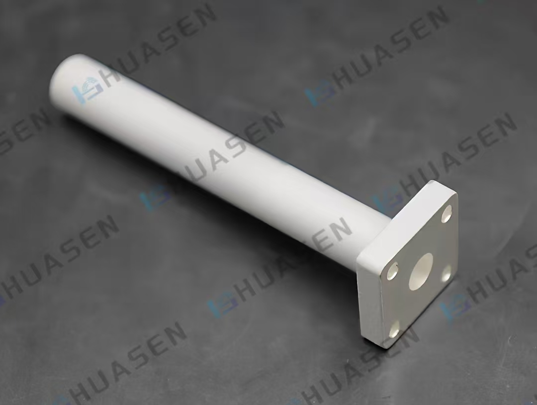
Huasen Microwave's Advanced Circular Waveguide Termination Solutions
Huasen Microwave Technology has developed state-of-the-art Circular Waveguide Termination products that exemplify optimization principles discussed throughout this guide. The company's terminations utilize precision-engineered conical structures with bulk absorption materials that efficiently absorb multiple electromagnetic modes propagating within circular waveguides. This design approach enables exceptional performance characteristics, including frequency coverage from 1.76 GHz extending to 116 GHz, accommodating applications spanning from L-band through W-band frequencies. The VSWR specification of 1.15 or better across the full frequency range ensures minimal signal reflection, making these terminations ideal for precision measurement systems where even small reflections could compromise accuracy.
The power handling capability of 20 kilowatts continuous wave represents substantial capacity suitable for demanding radar, telecommunications, and scientific research applications. This impressive power specification results from careful thermal design incorporating efficient heat dissipation pathways and robust absorber materials that maintain stable electrical properties under thermal stress. The TM01 mode compatibility ensures versatility across various circular waveguide configurations, while customization options for inner diameter dimensions enable integration into diverse system architectures. Manufacturing excellence backed by ISO9001 certification and rigorous quality control processes guarantees consistent performance and long-term reliability.
Huasen Microwave's three decades of experience in microwave and millimeter-wave component development provides unique insight into customer requirements across aviation, aerospace, telecommunications, and defense sectors. The company's comprehensive manufacturing capabilities include advanced CNC machining, precision waveguide fabrication techniques, and specialized composite material production that support custom Circular Waveguide Termination designs tailored to specific application needs. With over 200 skilled employees, multiple production workshops exceeding 3,000 square meters, and extensive testing infrastructure including multiple anechoic chambers and more than 60 advanced measurement instruments, Huasen delivers components that meet the most demanding performance specifications.
Conclusion
Optimizing Circular Waveguide Termination for power loads requires integrated consideration of electrical, thermal, and mechanical design parameters. Success depends on careful absorber material selection, precise geometric configuration, effective thermal management, and rigorous performance validation.
Cooperate with Huasen Microwave Technology Co., Ltd.
Partner with a China Circular Waveguide Termination factory that combines 30 years of expertise with cutting-edge manufacturing capabilities. As a leading China Circular Waveguide Termination supplier and China Circular Waveguide Termination manufacturer, Huasen Microwave delivers High Quality Circular Waveguide Termination solutions with competitive Circular Waveguide Termination price. Our extensive China Circular Waveguide Termination wholesale options and premium Circular Waveguide Termination for sale ensure your project succeeds. Contact our engineering team at sales@huasenmicrowave.com to discuss custom specifications, request technical documentation, or receive detailed quotations for your next high-performance RF system. Bookmark this page for quick reference when designing advanced waveguide architectures.
References
1. Kumar, Jitendra, Raj Singh, and V. P. Anitha. "Design and Development of a Circular Waveguide Terminator for Microwave Plasma Interaction Experiments." Progress In Electromagnetics Research M, 2019.
2. Clarricoats, P. J. B. and A. D. Olver. "Corrugated Horns for Microwave Antennas." IEE Electromagnetic Waves Series, 1984.
3. Balanis, Constantine A. "Advanced Engineering Electromagnetics." John Wiley & Sons, 2012.
4. Collin, Robert E. "Foundations for Microwave Engineering." IEEE Press, 2001.
5. Pozar, David M. "Microwave Engineering." John Wiley & Sons, 2011.
Send Inquiry


Related Industry Knowledge
- Is Near-Field Probe Measurement a "Relative" Test? What Does That Mean for Antenna Validation?
- What is a Waveguide Tube, and how does it differ from ordinary coaxial cables in signal transmission?
- What is the working principle of a waveguide sliding short?
- How to Use a Coaxial Fixed Attenuator in RF Testing (With Common Mistakes to Avoid
- Coaxial Load vs. Coaxial Attenuator: What’s the Difference?
- How to Use a Coaxial Directional Coupler for 5G Base Station Power Monitoring?
