What Determines the Q-Factor of a Waveguide Filter?






2026-07-28 10:40:36
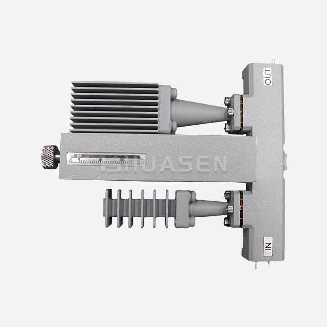
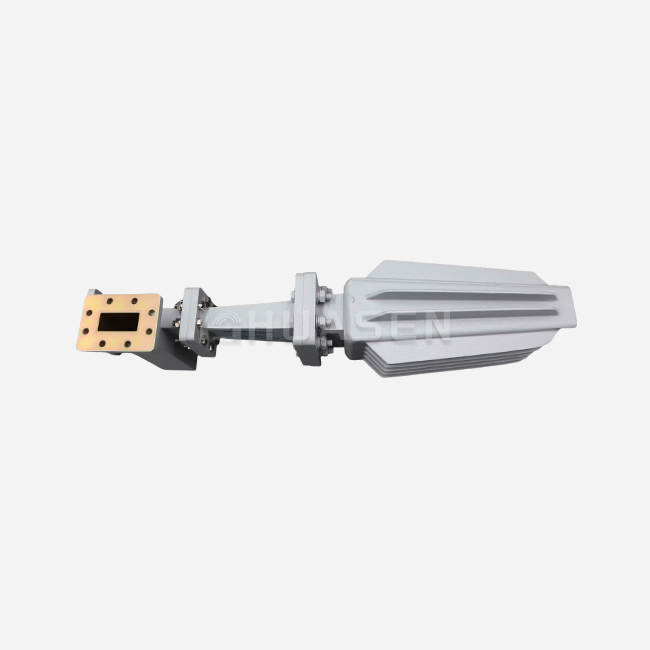
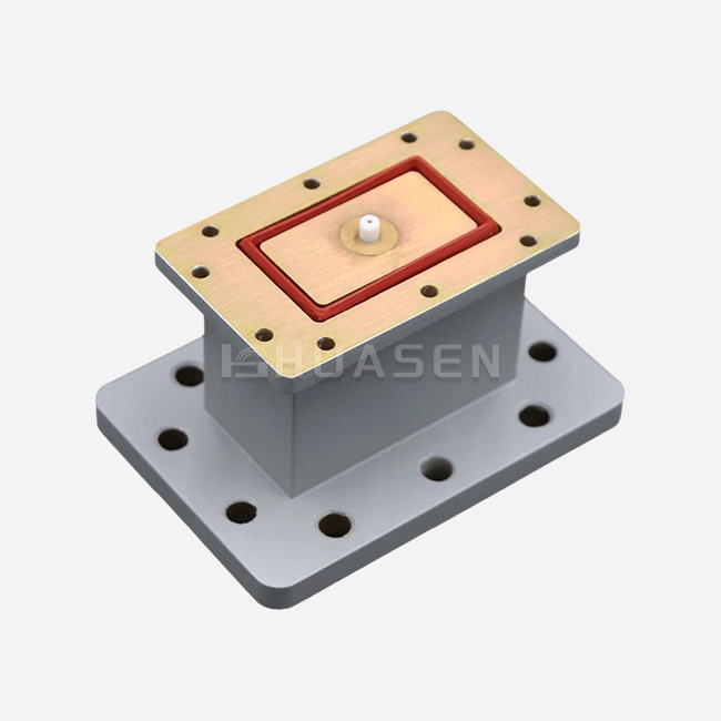
When I work with RF engineers and procurement teams across satellite, radar, and 5G infrastructure projects, one question consistently surfaces: what makes a waveguide filter's Q-factor so critical? The Q-factor of a waveguide filter is fundamentally determined by the ratio of energy stored within its resonant cavities to the energy dissipated through conductive losses, radiation leakage, and dielectric absorption. Waveguide filters achieve exceptionally high Q-factors because they leverage air-filled or low-loss dielectric resonant structures enclosed in precision-machined metal housings, minimising resistive losses at microwave and millimetre-wave frequencies. Material conductivity, surface roughness, cavity geometry, coupling iris dimensions, and temperature stability all directly influence this vital performance metric, making the Q-factor a true measure of filtering sharpness and signal integrity.
Understanding the Q-Factor in Waveguide Filters
The quality factor, or Q-factor, measures how well a resonant system saves energy compared to how much energy it loses during a vibration cycle. When it comes to RF and microwave filtering, high Q-factors directly mean better adjacent-channel rejection, sharper frequency selectivity, and less insertion loss. These are all very important for base station front-ends, satellite uplinks, and radar transmitters that work in environments with a lot of other signals.
Why Does Q-Factor Matter in High-Frequency Systems?
When frequencies go above 1 GHz, parasitic losses become more likely to affect the purity of the data. A high Q-factor makes sure that only the desired passband frequencies get sent through the chain, while harmonics and random sounds that aren't wanted are strongly cancelled out. This selectivity keeps sensitive devices safe from interference and makes sure that FCC and ETSI spectrum masks are followed. To keep link budgets that are measured in fractions of a decibel, engineers working on 5G massive MIMO arrays or Ka-band SATCOM terminals need filters with Q-factors above 5,000.
The Physical Foundation of Q-Factor
Resonant cavities inside hollow metal waveguides have very little dielectric loss compared to lumped-element or microstrip filters. This is because the electromagnetic field mostly moves through air. Standing wave patterns are limited by the walls of the waveguide, which are usually made of high-conductivity copper or aluminium and silver-plated to lower surface resistance. The quality of these metal surfaces, which is measured in microinches of hardness, has a direct effect on how energy is lost. Even very small flaws can spread out RF currents, turning signal energy into heat and lowering the Q-factor.
Loaded vs. Unloaded Q-Factor
People who work in procurement should know the difference between empty Q (Qu), which shows the resonator's own losses, and loaded Q (QL), which takes into account system impedance matching and coupling from outside the system. If you connect a filter with Qu = 8,000 to a 50-ohm gearbox line, the QL value might drop to 3,500 because of coupling losses at the input and output ports. Knowing this difference helps buyers correctly read datasheets and avoid over-specifying filters that are too powerful for the system, which cuts down on costs and wait times that aren't needed.
Key Factors Influencing the Q-Factor of Waveguide Filters
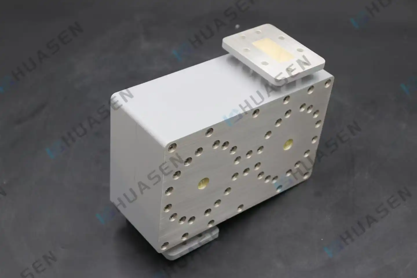
The achievable Q-factor in real-world waveguide filter implementations is controlled by a number of interconnected design parameters. When procurement teams know about these things, they can more confidently look at how well suppliers meet requirements and the trade-offs between specifications.
Material Selection and Conductivity
The choice of metal types is the most important part of optimising the Q-factor. Copper is a better conductor of electricity (5.96 × 10⁷ S/m), so there are fewer ohmic losses along the walls of cavities. Aluminium has a good strength-to-weight ratio for aerospace uses, but it has a slightly higher resistivity. Brass is in the middle of these two extremes. It is often chosen because it is easy to work with and doesn't change size much. Silver or gold plating, which is usually 2 to 5 microns thick, lowers surface resistance even more. This is especially true at millimetre-wave frequencies, where the skin layer drops below 1 micron.
| Material | Conductivity (S/m) | Typical Surface Finish | Relative Q-Factor Impact | Common Applications |
|---|---|---|---|---|
| Copper | 5.96 times 10 | Plated in silver | The best | High-power radar and satellite ports |
| Aluminium | 3.77 times 10 | Been anodised or plated | High | Aerospace equipment that needs to be light |
| Brass | 1.57 times 10 | chromed or polished | Moderate | Lab tools and test equipment |
| Invar | 1.39 × 10 | Coatings for specific uses | Lower (focus on heat stability) | Space-grade screens that adjust for temperature |
The temperature coefficient of expansion is also important for a waveguide filter. Invar metals keep their shape even when the temperature inside a spaceship goes through huge changes. This stops frequency drift, even though the Q-factor may be slightly lower than with pure copper implementations.
Geometric Precision and Cavity Design
The size of the cavity has a huge effect on the resonance frequency and Q-factor. A mistake in machining of 10 microns in a Ku-band cavity can move the centre frequency by several megahertz and lower the Q-factor by 15 to 20 per cent. Electrical discharge machining (EDM) makes it possible to make complex internal shapes like smooth coupling irises and tuning posts, and modern CNC machining centres can hold limits of just ±5 microns. The aspect ratio of holes (height compared to cross-sectional area) affects the purity of the mode. Parasitic modes that compete with the main TE₁₁ or TM₀₁ mode scatter energy and lower the effective Q.
Insertion Loss and Energy Dissipation
Insertion loss measures how much signal power is lost as RF energy passes through the filter. For every 0.1 dB of insertion loss, about 2.3% of the signal power is lost as heat, which directly lowers the loaded Q-factor. High-power filters for radar emitters have to handle kilowatts of pulsed or steady wave energy without overheating. Skin-effect losses are lower at high frequencies when silver plating is used. Integrated heat sinks or cooling channels help keep the working temperature fixed, which keeps the Q-factor and frequency accuracy.
Coupling Mechanisms and Bandwidth Trade-offs
Iris-coupled cavity filters control the rate of energy transfer by placing precisely sized holes between resonators that are next to each other. Tighter coupling, which means bigger eye holes, raises bandwidth but lowers the Q-factor by adding more paths for loss. Engineers have to find a balance between selectivity and fractional bandwidth. For example, an X-band filter with 1% bandwidth can reach Q-factors above 10,000, while a design with 10% bandwidth may reach a limit around 1,500. To make sure that expectations are reasonable and to avoid expensive redesigns, procurement specifications should clearly state bandwidth needs along with Q-factor goals.
Comparison of Waveguide Filter Types and Their Q-Factor Performance
Filter architectures with different Q-factor profiles can meet the needs of different applications. Procurement managers can make choices about technology that fits system-level performance goals and budget limits when they understand these trade-offs.
Cavity resonator filters are the most common type used in high-power situations. This is because the air-filled holes make them safer than solid-state options that could break down. The Q-factor can be anywhere from 3,000 to 12,000. It depends on the frequency band and the size of the cavity. These filters work great in base station diplexers and satellite transponders that handle more than 100 watts of power on average.
High-permittivity ceramic pucks (εr = 20 to 90) are used in dielectric resonator filters to make the actual size three times smaller than with air-filled holes. Because of electrical losses in the ceramic material, the trade-off is lower Q-factors, usually between 1,500 and 5,000. These small designs work well for mobile base stations that don't have a lot of room and phased array antennas, where size and weight are more important than ultimate selectivity when deciding what to buy.
Corrugated low-pass filters have ridge structures inside that make capacitance and inductance spread out. This stops harmonic frequencies above the basic passband. Even though these filters aren't designed to work best with high Q-factors (usually between 500 and 2,000), they are necessary for reducing harmonics in amplifier output stages and frequency multiplier chains. Because they are mechanically strong and don't react to changes in temperature, they are good choices for outdoor installations and harsh environments.
E-plane filters put thin metal fins along the electric field plane of the waveguide. This makes resonant sections with Q-factors between 2,000 and 6,000. The fin-line structure makes it possible to make small designs that work for millimetre-wave frequencies (Ka-band to W-band), where regular cavity filters would be too small to be useful. When looking at 5G backhaul or automotive radar applications, procurement teams should know how fin-line filters balance performance and manufacturability at frequencies above 30 GHz.
| Filter Type | Q-Factor Range | Power Handling | Frequency Range | Physical Size | Typical Cost Relative |
|---|---|---|---|---|---|
| Space filled with air | 5,000 to 12,000. | >1 kW | 1–40 GHz | Big | Starting point (1.0) |
| Resonator for dielectric | 1,500 to 5,000 | ~500W | 0.5 to 20 GHz | Closed | 0.7 to 0.9 |
| Flat (low-pass) corrugated | 500 to 2,000 | KW+2 | 1 to 100 GHz | A Medium | 0.5 to 0.7 |
| E-plane/fin-line | 2,000 to 6,000 | ~200W | 10 to 100 GHz | Not very big | 1.2–1.5 |
| Coaxial cavity | 1,000 to 3,000 | ~300W | 0.5 to 6 GHz | A Medium | 0.6 to 0.8 |
This performance matrix helps people who buy things make sure that filter technology fits the needs of the project. A 5G macro base station sending 200 watts at 3.5 GHz would benefit from air-filled cavity filters because they offer the best Q-factor and power handling. On the other hand, a small-cell installation sending 20 watts might choose dielectric resonator designs because they are cheaper and smaller, even though they have slightly lower Q-factors. Waveguide filters can also be considered based on specific project requirements.
Practical Considerations for Procuring Waveguide Filters with High Q-Factor
To successfully buy high-performance waveguide filters, you need to pay attention to more than just the unit price. You also need to look at the supplier's capabilities and the total cost of ownership.
Specification Evaluation and Performance Verification
It should be clear on the datasheets what the empty and loaded Q-factors are for the given temperature range. If the specs only list performance at room temperature, be careful. Thermal drift can lower the Q-factor by 10 to 30 per cent at high and low temperatures. Ask for measured S-parameter files in Touchstone format that include insertion loss, return loss, and group delay for the whole passband and stopband. Before agreeing to production orders, these datasets allow system-level models that guess link budget margins.
Customisation Capabilities and Engineering Support
For many uses, custom frequency plans, certain flange types (UG-style, EIA, or metric), or built-in combining features are needed. Suppliers that use HFSS or CST Microwave Studio for in-house electromagnetic modelling can make changes to designs quickly, cutting the time it takes to make a sample from weeks to days. Ask about tolerance stack-up analysis during technical discussions. This is how differences in manufacturing affect the final Q-factor and yield rates as they move through the assembly stages. Mature providers give statistical process control data that shows that performance is the same across all production lots.
Certification, Reliability, and Supply Chain Stability
MIL-STD-461 for electromagnetic interference, MIL-STD-810 for environmental ruggedisation, and AS9100 quality control systems must all be followed by military and aircraft projects. More and more, commercial buyers of telecommunications equipment want lead-free products that are certified by ISO 9001 and RoHS. Obsolescence management should be part of long-term supply agreements. Waveguide filters usually last 10 to 20 years, longer than individual component generations. Before going into production, make sure you have clear terms for remanufacturing, recalibration services, and the availability of spare parts.
Lead Time and Minimum Order Quantities
Catalogue filters usually ship in two to four weeks, but custom waveguide Filter designs need six to twelve weeks for electromagnetic optimisation, CNC machining, tuning, and testing. With 3D-printed or soft-metal cavities, prototyping services can speed up proof-of-concept confirmation to 10 business days, but the final Q-factors will be smaller than those for production units. Minimum order quantities are very different. Well-known manufacturers may need between 50 and 100 pieces for custom configurations, while specialised suppliers that focus on R&D markets will accept orders for just one unit at a higher price. Finding the right balance between these factors and project deadlines and budget limits is what separates good procurements from launches that are late.
Conclusion
Knowing about materials, making things precisely, and electromagnetic design all work together to create a waveguide filter's Q-factor. High-conductivity metals with surface finishes that are less than a micron thick reduce resistance losses, and micron-sized variations in dimensions keep the resonant mode pure and the frequency accurate. When buying something, you have to weigh the absolute Q-factor against things like internet needs, power handling, environmental durability, and the total cost of ownership. For high-power uses, air-filled cavity filters have the best Q-factors, while dielectric-loaded options are smaller and better for installations with limited room. When you understand these trade-offs and carefully check a supplier's customisation options, certifications, and technical support, you can be sure that the filters you choose will meet both short-term performance goals and long-term reliability standards for satellite, radar, and telecommunications applications that are very demanding.
FAQ
1. What Q-factor range should I expect for commercial waveguide filters?
For frequencies between 1 and 18 GHz, commercial cavity filters usually have Q-factors of between 3,000 and 8,000. Designs for millimetre waves above 30 GHz usually get between 2,000 and 5,000 because of tighter production tolerances and hits from rougher surfaces. With the help of special materials and very precise machining, custom laboratory-grade screens can hold more than 10,000 particles.
2. How does insertion loss directly affect Q-factor?
Insertion loss measures how much energy is lost, which has a negative effect on the full Q-factor. When compared to a 0.2 dB design, a filter with 0.5 dB insertion loss loses about 11% of its output power to heat. There is a strong link between lower insertion loss and higher Q-factors, but bandwidth and coupling mechanisms are also very important.
3. Can waveguide filters be customised for specific frequency bands?
Of course. Reliable suppliers can make custom designs that cover specific passbands, ranging from UHF to W-band. Centre frequency, bandwidth, rejection depth, flange types, and power handling are all things that can be changed. Custom filters take 6 to 12 weeks to build, prototype, and tune, while catalogue things only take 2 to 4 weeks.
Partner with Huasen Microwave for Superior Waveguide Filter Solutions
Since 1993, Huasen Microwave has been providing precision-engineered RF and microwave parts to defence contractors, aerospace programmes, and telecommunications infrastructure around the world. Our waveguide filter line includes cavity resonators, dielectric-loaded designs, and harmonic reduction filters. All of them are made to strict Q-factor standards that go over 8,000 at the X-band. Each unit goes through full S-parameter characterisation at all temperature ranges, and test results are sent along with certificates of calibration. Our engineering team can help you with design, make quick prototypes, and give you quick technical support whether you need a high-Q waveguide filter supplier for 5G massive MIMO base stations or custom Ka-band satellite filters with built-in multiplexers. Email our sales team at sales@huasenmicrowave.com to talk about your application needs, get performance data, or get quotes for prototypes and production amounts.
References
1. Matthaei, G. L., Young, L., & Jones, E. M. T. (1980). Microwave Filters, Impedance-Matching Networks, and Coupling Structures. Artech House.
2. Cameron, R. J., Kudsia, C. M., & Mansour, R. R. (2007). Microwave Filters for Communication Systems: Fundamentals, Design, and Applications. Wiley-Interscience.
3. Pozar, D. M. (2011). Microwave Engineering (4th ed.). John Wiley & Sons.
4. Hunter, I. C. (2001). Theory and Design of Microwave Filters. IET Press.
5. Collin, R. E. (1992). Foundations for Microwave Engineering (2nd ed.). IEEE Press.
6. Rhodes, J. D. (1976). Theory of Electrical Filters. John Wiley & Sons.
Send Inquiry