PIN Diode Power Limiter: How It Shields Your Frontend






2026-07-27 10:02:27
When your sensitive receiver components face the constant threat of high-power signal spikes, you need a protection strategy that responds in nanoseconds without compromising signal quality. A PIN diode power limiter acts as an intelligent guardian at your RF frontend, automatically clamping excessive power levels while maintaining transparency to normal signals. Unlike conventional protection circuits that introduce significant loss or react slowly, these passive devices leverage the unique physics of PIN junction semiconductors to transition from low-loss transmission to high-attenuation states almost instantaneously when input levels exceed safe thresholds, preserving the integrity of downstream amplifiers, mixers, and detectors in mission-critical applications.
Understanding PIN Diode Power Limiters and Their Function
What Makes PIN Diode Technology Unique?
PIN diodes are fundamentally different from regular rectifier diodes because they have an intrinsic region (I-layer) between the P and N semiconductor layers. This design makes a part of variable resistance that changes a lot depending on the amount of RF power. The device has very low resistance at low signal levels, so data can pass with insertion losses usually less than 1.5 dB. When the input power goes over the threshold level, which is usually between +10 dBm and +20 dBm, charge carriers flood into the intrinsic layer. This makes it much more conductive and sends any extra energy to the ground before it can damage any parts.
Core Operational Principles
The safety system doesn't need an external bias voltage to work, so it's always reliable even in harsh conditions. Response times are less than 100 nanoseconds, which is very important for radar systems that need to find weak target returns right after high-power transmit pulses. The gadget keeps flat leakage power below 20 dBm and spike leakage energy below 0.5 ergs. These specs are directly related to the ability of expensive low-noise amplifiers in electronic warfare receivers and satellite transponders to work.
This technology is also useful for commercial internet systems. Base station frontends in 5G networks have to deal with interference from nearby high-power transmitters. A broadband power limiter keeps the receiver linearity and stops saturation, which would otherwise create coverage blind spots. In this case, the low insertion loss property is very important—every tenth of a dB matters when the system noise figure decides how well the cell edge works.
Integration in Modern RF Architectures
These parts are usually put right after the antenna or in the first stage of the receiver chain by engineers. When space is limited, the mechanical form factor is very important for things like UAV communication systems or phased array radar modules. Standardized SMA or K-type connectors on devices that weigh less than 100 grams make it easier to add them to current designs without having to rethink the hardware.
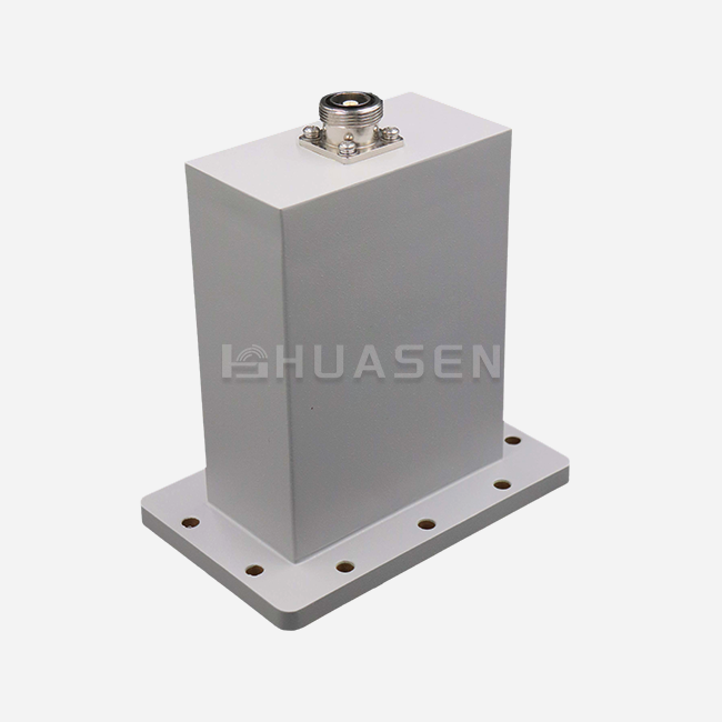
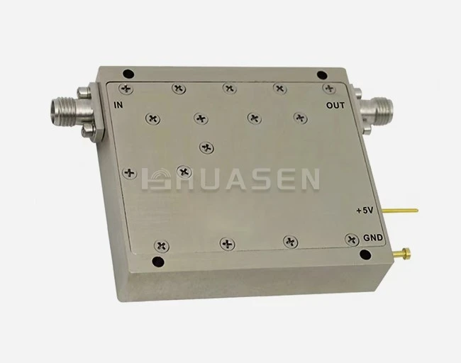
This way of thinking is shown by Huasen Microwave's Broadband Power Limiter (LT series). The nickel-plated aluminum shell doesn't rust in salty seawater and has great thermal conductivity, which is important because managing junction temperature directly affects how much power a device can handle. Each unit goes through a lot of tests across its frequency range. The loss, VSWR, and power transfer models are written down so that exact system-level performance predictions can be made.
Comparison of PIN Diode Power Limiters with Alternative Solutions
| Protection Technology | Response Time | Insertion Loss | Peak Power Handling | Recovery Time | Best Use Case |
|---|---|---|---|---|---|
| PIN Diode Limiter | <100 ns | 0.8 to 2.5 dB | Pulse up to 1 kW | <50 ns | Readers for RF and microwaves |
| Gas Discharge Tube | (1–5)µs | <0.3 dB | 10 kW or more | 50–100µs | Protection for antennas, low-frequency |
| Varistor (MOV) | 25 to 50 ns | varies | Lots of energy | Slow down | Protection for the power supply input |
| Active Limiter Circuit | 10-50ʵs | 3–6 dB | Limited | Different | Low-frequency sound or instruments |
The table shows why inactive PIN power limiters are most common in microwave settings. Gas discharge tubes are better at handling power, but their reaction times of microseconds make blind spots in pulsed radar systems that aren't acceptable. In power distribution, varistors are good at handling short-term energy surges, but they aren't precise or low-loss enough to keep signal-to-noise ratios high in communications devices.
Cost-Effectiveness in System Design
When procurement managers figure out the total cost of ownership, they need to take replacement costs into account. In a radar system, an unprotected low-noise amplifier could cost $5,000 to $15,000, and it could take months to get it. A good power limiter that costs $300 to $800 stops one failure and then cancels out its own costs. Buying in bulk for base station deployments or satellite groups can save you money because makers offer tiered pricing that makes profits better for orders over 100 units.
Because they are inactive, they don't need to worry about power usage or the different ways they could fail that come with active bias circuits. In aerospace applications that use reliability calculations to choose parts, the solid-state design and hermetic sealing of high-grade limiters help reach system-level MTBF (Mean Time Between Failures) goals in a measurable way.
Installation, Operation, and Troubleshooting of PIN Diode Power Limiters
Proper Integration Techniques
Impedance matching across the operational bandwidth is the first step to a successful deployment. To keep echoes to a minimum, the power limiter needs to have a characteristic impedance of 50 ohms (or 75 ohms for broadcast uses). The way the device is mounted affects how much heat it loses. Putting the body of the device in touch with chassis ground planes or heat sinks increases its ability to handle continuous-wave power.
The torque specs for connectors are more important than many engineers think. When you overtighten SMA interfaces, the center conductor alignment is harmed. This causes impedance discontinuities that show up as VSWR spikes at certain frequencies. Under-tightening lets small movements happen during earthquake exposure, which is a big problem for installations in the air or on ships where MIL-STD-810 compliance requires them to keep working even when shocks happen.
Diagnostic Procedures and Common Failures
When performance goes down, it usually shows up as higher flat leakage power or higher insertion loss. Through S-parameter measurements, a validated vector network analyzer can quickly find these problems. When you compare measurements from the field to the original test data from the factory, you can see drift patterns that show when something is about to fail before it does.
The main cause of failure is thermal overstress. When the average input power goes over the rated continuous-wave specification, which is usually between 1 and 5 watts based on the type, the junction temperature rises too high to be safe. The diode fails into a low-impedance state, giving up its own function to short the input and saving the more valuable LNA downstream most of the time. This fail-safe feature adds an extra layer of security, but the power limiter needs to be replaced.
Outdoor phone lines wear out faster because of the weather and other environmental factors. Bond wires corrode when moisture gets in through broken seals, and solder joints get stressed when temperatures change in deserts or the polar regions. In difficult operations, these worries go away when devices with hermetic sealing tested according to MIL-STD-883 methods are used.
Procurement Guide: Choosing and Buying PIN Diode Power Limiters for Your Business
Critical Specification Parameters
Technical buyers need to carefully review specifications to make sure that the features of the parts match the needs of the application. Frequency coverage is based on bandwidth. Octave or multi-octave devices that cover 2-18 GHz or even DC to 40 GHz in millimeter-wave uses are best for communication systems that use more than one band. When frequency agility isn't needed, narrower bandwidths often have better insertion loss performance.
Pay close attention to the limiting threshold. If you set this setting too low, it will weaken valid high-level signals for no reason, which will lower the dynamic range. When thresholds are set too high, amounts of damaging power can get through. Radar warning devices might need +15 dBm limiting to protect against enemy jamming, while test equipment might need +10 dBm thresholds to keep probes from accidentally touching live circuits.
| Specification Parameter | Typical Range | Application Impact | Selection Criteria |
|---|---|---|---|
| Frequency Coverage | 0.5 to 40 GHz | Finds systems that are similar | Match the system's bandwidth plus 10%. |
| Insertion Loss | 0.8 to 2.5 dB | Changes the noise figure | Lessen the sensitivity of the receiver |
| Limiting Threshold (P1dB) | +10 to +20 dBm | Sets the point at which safety will kick in | 5 to 10 dB below the damage level |
| Peak Power Handling | 100 W to 1 kW | Getting through beats | Match situations where the transmitter is close. |
| VSWR | 1.6:1 is normal | Signal speed and reflection | Values that are lower for broad matching |
Supplier Evaluation and Quality Assurance
Traceability is kept up by well-known makers using serialised power limiter parts with test data that can be found. This dedication is shown by the multiple performance charts that come with every LT series unit from Huasen Microwave Technology, which has been in business since 1993. This paperwork helps system engineers model exact behaviour under different input conditions, which speeds up integration and cuts down on the number of prototype rounds.
Certification compliance is very important, especially in the aerospace and defence industries. Products made to MIL-STD-883 standards go through tests like temperature cycling, mechanical shock, fine/gross leak testing, and burn-in screening that parts made for consumers don't have to go through. RoHS compliance shows that you care about the environment and can sell your products in European markets. ISO 9001 certification shows that your quality control systems are strong.
Project plans are affected by lead times and the security of the supply chain. Dual-sourcing strategies lower risk, but because different manufacturers' products don't always work the same way, they need to be requalified. Long-term supply agreements with well-known suppliers make sure that parts for products that last ten years or more are always available. These kinds of products are common in defence systems and telecommunications infrastructure.
Future Trends and Innovations in PIN Diode Power Limiters
Emerging Semiconductor Technologies
Gallium nitride (GaN) and silicon carbide (SiC) surfaces offer better performance limits. These materials with a wide bandgap can handle higher junction temperatures, which directly improves their ability to handle steady waves of power and peak pulses. GaN-based limiters that are still being worked on show flat operation above 50 GHz. This means that they can be used for millimetre-wave applications in 5G backhaul links and automotive radar systems that work at 77–81 GHz.
The merging of smart tracking is another new area of research. Putting temperature sensors and telemetry interfaces in infrastructure that is far away, like communications towers at offshore wind farms or ground stations for satellites in the Arctic, lets people check on its health in real time. Predictive maintenance algorithms look at patterns in performance and plan replacements for planned downtime instead of after something breaks.
Expanding Market Applications
As small-cell 5G base stations become more common, there is a huge need for small, low-cost defence components. Small cells are put on streetlights and building surfaces, where interference can happen more often than in macro-cell towers, which have controlled RF environments. Power limiters that are the right size for these uses match efficiency with costs per unit that can be used at millions of sites.
Drone-based communications devices have special needs. They need to be light (less than 50 grams), and they need to be able to handle vibrations, so they need to be built in a tough way. Counter-UAS (unmanned aerial systems) gear that protects important infrastructure needs limiters for a variety of frequency bands as threats change how they work.
Applications in space push the limits of reliability even further. For world internet coverage, satellite systems use thousands of transponders, and each one needs to be protected by a power limiter from solar events and high-power uplinks. Radiation-hardened designs and extended qualification tests make sure that orbital activity will last for ten years without the need for upkeep.
Conclusion
To keep weak RF front ends safe, you need more than just general surge suppression. You need engineered solutions that match the threat profile in terms of response speed, insertion loss, and power handling. PIN diode power limiters provide this level of accuracy through passive, tried-and-true technology that works on everything from lab benches to space platforms. Engineers and buyers can choose parts that will keep systems running smoothly and avoid catastrophic failures by understanding the operating principles, comparative benefits, and procurement factors. As wireless technologies get better at higher frequencies and denser deployments, these protection devices will stay essential to make sure that they can keep working in electromagnetic settings that are getting more dangerous.
FAQ
1. What input power levels can PIN diode limiters safely handle?
Peak power handling for pulsed signals with short duty cycles is between 100 watts and 1 kilowatt. For continuous waves, the rates run from 1 to 10 watts, depending on how well the heat is managed. If you go over these limits, the junction could be damaged permanently. Always compare the peak and average power values to your worst-case working scenarios, such as transmitter leakage close by and reflected power from antenna mismatches.
2. How do I select the appropriate limiting threshold for my application?
Find the highest level of safety that your most sensitive downstream part can handle, which is usually the low-noise amplifier, and then take 5 to 10 dB away as a safety cushion. This is now your needed limiting threshold. In passive PIN implementations, there are no devices with thresholds that can be changed. You have to choose the right fixed limiting threshold when you place your order. Most of the time, radar systems need activation points of +13 to +17 dBm, while test equipment security needs activation points of +10 dBm.
3. Can these devices protect against lightning strikes or EMP events?
PIN Power Limiters are very good at handling short bursts of radio frequency (RF), but they're not made to handle the huge amounts of energy that come from lightning hits or nuclear EMPs. For these threats, you need a staged defence system with gas discharge tubes, metal-oxide varistors, and chassis-level shielding as the main defences and PIN power limiters for the last level of precision protection. The cap protects against common operating risks, such as signals getting jammed or transmitters leaking.
Secure Your RF Frontend with Huasen Microwave Power Limiter Solutions
To keep mission-critical receiver chains safe, you need parts that are built to last and technical support that is quick to respond. The Broadband Power Limiter (LT series) from Huasen Microwave Technology blends 30 years of production experience with strict quality standards to make aluminium nickel-plated housings that weigh less than 100 grams and fit easily into designs that don't have a lot of room. Our thorough testing methods record loss, VSWR, and power transfer traits across the entire operational bandwidth. This gives your engineers the performance reliability they need. Our team can help you with design, sample evaluation programmes, and bulk prices that fit your budget cycles, whether you're setting up 5G infrastructure, upgrading radar systems, or protecting satellite transponders. Get in touch with our applications engineers at sales@huasenmicrowave.com to talk about your front-end protection needs with a reputable power limiter manufacturer. We'll help you find the best solution and give you delivery dates that keep your projects on track.
References
1. Rizzi, P.A. (1988). Microwave Engineering: Passive Circuits. Englewood Cliffs: Prentice Hall, Chapter 8: Limiters and Protective Devices.
2. Golio, M. & Golio, J. (2018). RF and Microwave Passive and Active Technologies. Boca Raton: CRC Press, Section 12.4: PIN Diode Limiter Design.
3. Caverly, R.H. & Hiller, G. (2002). Establishing the Minimum Reverse Bias for a p-i-n Diode in a High-Power Switch. IEEE Transactions on Microwave Theory and Techniques, 50(12), 2938-2942.
4. MIL-STD-883K. (2019). Test Method Standard: Microcircuits. United States Department of Defence, Method 3102: Hermetic Seal Testing.
5. Gupta, K.C. & Bahl, I.J. (1979). Microstrip Lines and Slotlines. Norwood: Artech House, Chapter 7: Passive Control Components.
6. ITU-R Recommendation SM.1446-1. (2000). Definition and Measurement of Intermodulation Products in Transmitter and Receiver Front-Ends. International Telecommunication Union, Geneva.
Send Inquiry