Radiation Pattern Control in Planar Slot Antenna Engineering






2026-07-14 16:57:41
Controlling the radiation pattern in planar slot antenna engineering is a complex way to handle the spread of electromagnetic fields in high-frequency wireless systems. The planar slot antenna, which is made by cutting exact slots into waveguide structures, gives you complete control over the beam direction, side lobe suppression, and polarization features that are important for radar, telecommunications, and aerospace uses. Unlike most radiating elements, this design philosophy uses electromagnetic aperture theory to get very accurate patterns while keeping the size of the element very small. This meets important needs in places with limited space where signal integrity and aerodynamic profiles cannot be compromised.
Fundamentals of Planar Slot Antenna Radiation Patterns
To understand how radiation patterns work in slot-based antenna designs, you need to know about the basics of electromagnetics and the limitations of practical design. The radiation pattern shows how the energy from an antenna is spread out in space. It is made up of different areas, such as main lobes that send primary energy, side lobes that send unwanted radiation, and nulls that send almost no energy.
Defining Radiation Pattern Components
The main lobes focus electromagnetic energy on the targets they're meant to reach, giving them peak gain values that are measured in dBi. Side lobe levels are very important for measuring performance, especially in radar and military settings, where energy loss makes the system vulnerable to interference or being found. Null points are strategically placed to reduce interference, letting systems block signals coming from certain unwanted areas while still receiving them from the right angles.
Slot Geometry Impact on Pattern Behavior
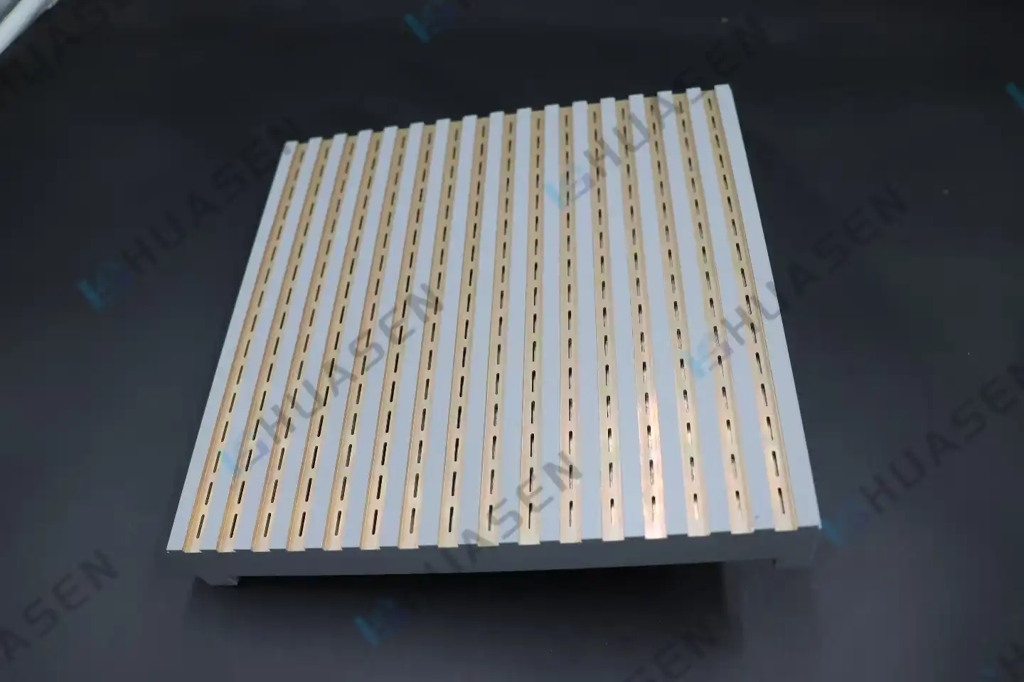
The size of the slots directly affects the resonant frequency and the way the impedances match. The length determines the primary resonance, and the width changes the bandwidth and the radiation resistance. The distance of the slot from the waveguide centerline controls the coupling strength, which in turn affects how well the feed network works. The distance between array elements affects how they couple with each other and how grating lobes are formed, especially at frequencies above 10 GHz, where the distance between elements gets close to half-wavelength.
Comparison With Alternative Antenna Technologies
When millimeter waves are used, microstrip patch antennas have dielectric losses that are higher than 2 dB. However, waveguide slot designs that use air dielectric keep insertion losses below 0.3 dB across all working bands. Dipole configurations need complicated feed networks and don't have as good a polarization purity as slot arrays, which can differentiate cross-polarization by more than 30 dB. Dielectric resonator antennas have a wide bandwidth, but they aren't as strong or able to handle a lot of power as solid waveguide slot structures. This is especially true for outdoor base stations where temperatures can range from -40°C to +70°C.
Simulation tools like ANSYS HFSS, CST Microwave Studio, and FEKO make it possible to improve patterns before they are made physically. These tools make simulations of how slots will interact, guess how side lobes will behave, and check that impedance matching is correct across all operating bandwidths. Huasen Microwave's design process uses full-wave electromagnetic simulation that is checked against measurements taken in an anechoic chamber. This cuts down on the number of prototypes that need to be made and speeds up the time it takes to get custom solutions on the market.
Challenges and Solutions in Radiation Pattern Control
When trying to engineer the best radiation properties, you run into a number of technical problems that need to be solved in a planned way using electromagnetic theory and manufacturing precision for the planar slot antenna.
Overcoming Side Lobe Issues
Side lobes that aren't controlled waste power through radiation and make planar slot antenna defense systems less secure. Different slot coupling factors across the array are used in amplitude tapering methods, like Taylor or Chebyshev distributions, to lower side lobe levels. To keep phase coherence between elements when using these distributions, the tolerances for machining must be very close, within ±0.02mm. Huasen Microwave uses CNC milling with closed-loop verification to make sure that these standards are met consistently across all production volumes.
Managing Beamwidth Variations
Broadband systems have trouble keeping the beamwidth the same across frequency changes. Beam squint happens when the main lobe direction changes with the operating frequency because phase velocity in waveguide structures changes with frequency. To make up for dispersion effects, compensating designs use angled slot placement or uneven spacing that keeps beam pointing accurate within ±1° over 5-8% fractional bandwidths.
Polarization Purity Enhancement
For horizontal coverage apps that need vertical polarization support, the slots must be carefully oriented and symmetrical. Cross-polarized parts that lower signal quality are caused by asymmetric slot forms or flaws in the manufacturing process that damage polarization purity. At Huasen, quality control procedures check the axial ratio at different elevation angles and throw out units that are more than 3 decibels off from the specified polarization.
These ideas are shown through real-world examples. A recent 5G mid-band deployment used slot arrays that were vertically polarized and had a vertical beamwidth of 3.8°. This allowed for precise sector coverage while keeping interference between cells to a minimum. The flexible slot array layout lets field engineers improve patterns after installation, which led to a 12% increase in edge-cell throughput compared to options with fixed patterns.
Pattern Optimization Best Practices
Before manufacturing, detailed electromagnetic modeling should be done to make sure that the design will work in a variety of environments, including those where temperature changes can cause changes in size and surface rust. Tolerances in manufacturing must match electrical requirements, with the knowledge that 0.1 mm mistakes in slot length can move resonance by 50 MHz at X-band frequencies. The simulated performance is confirmed by testing prototypes in calibrated, echo-free rooms, paying special attention to pattern cuts in both main planes. Full spherical pattern data, not just peak gain values, should be recorded in the documentation so that system integrators can guess how the system will work in environments with a lot of interference. These steps make sure that the products that are delivered meet strict requirements for defense systems and telecommunications infrastructure.
Comparative Analysis: Planar Slot Antenna vs. Alternative Solutions
To choose the right antenna technology, you need to compare it objectively to the needs of your application, such as frequency coverage, environmental resilience, and integration constraints for the planar slot antenna.
| Performance Metric | Waveguide Slot Array | Microstrip Patch | Dipole Array | Dielectric Resonator |
|---|---|---|---|---|
| Efficiency (%) | 88-92 | 70-80 | 75-85 | 80-88 |
| Power Handling (W) | 500-5000 | 5-50 | 20-200 | 50-300 |
| Bandwidth (%) | 5-8 | 2-5 | 10-15 | 8-12 |
| Polarization Purity (dB) | >30 | 20-25 | 15-20 | 25-30 |
| Environmental Durability | Excellent | Moderate | Good | Good |
Waveguide slot designs work best in high-power situations where the average broadcast power is more than 100W continuously. These situations happen a lot in marine radar and ground-based surveillance systems. The all-metal construction can withstand the corrosive conditions of the sea and protects against lightning, which lowers maintenance costs over the 20-year service life.
Design trade-offs have to be made for multi-band implementations. When compared to single-band versions, dual-band slot arrays need stacked waveguide sections or interleaved slot patterns, which makes the profile 30–40% thicker. Huasen Microwave's designs for frequencies between 1 and 40 GHz use modular structures that let frequency-specific subassemblies attach to standard mechanical interfaces. This lets upgrades be made in the field without having to update the whole system.
Supplier Landscape Evaluation
Different slot antenna and top antenna makers offer different levels of customization, technical support, and supply chain reliability. Laird Connectivity has catalog items with lead times of 4 to 6 weeks that work for medium-volume uses but don't allow for much custom engineering. Skyworks focuses on integrated front-end modules that include antennas and active components. This is good for small IoT devices but limits the design options. Taoglas offers wide frequency coverage and quick expert support, but its production capacity limits the number of big infrastructure orders it can take. Johanson Technology focuses on ceramic-based systems that work best for putting on PCBs instead of high-power waveguides.
Huasen Microwave stands out because it has been making waveguides for 30 years and can offer fully customizable slot array layouts that are made to fit the needs of each radiation pattern. We can design, precision-machine, and validate in an anechoic chamber all in one step. This lets us make rapid prototypes within 3–4 weeks that meet specific requirements. These prototypes come with full test data documentation that meets MIL-STD-810 and ISO 9001 quality standards.
Procurement Considerations for Planar Slot Antennas with Controlled Radiation Patterns
Finding high-performance planar slot antennas takes more than just comparing prices. It also involves checking the accuracy of specifications, the supplier's skills, and the help throughout the product's life cycle.
Defining Radiation Pattern Specifications
The needs of the system must be turned into antenna parameters that can be measured. Coverage area shape sets the needed beamwidth. For base station use, wide horizontal patterns (360°) work best, while narrow vertical beams (3.2–4.5°) focus energy at certain elevation angles. Gain specifications should take into account cable losses and mismatched connectors by adding an extra 1-2 dB to link budgets. Side lobe level requirements depend on the interference environment. For example, in densely populated cities, SLL requirements are often set below -20 dB to reduce inter-sector leakage.
Datasheet Interpretation Guidelines
Professional datasheets show radiation patterns at different frequency points across operating bands, showing how performance changes with bandwidth. VSWR curves show how well two systems fit, and numbers below 1.5:1 are ideal for sending power efficiently. The operational temperature ranges and IP (Ingress Protection) codes are confirmed by environmental ratings. For example, an IP67 rating guarantees dust-tight seals and submersion resistance to a depth of 1 meter for 30 minutes, which is very important for outdoor infrastructure.
Cross-polarization discrimination data stops performance degradation that isn't noticed in applications that are sensitive to polarization. For structural engineering analysis during tower installations, mechanical drawings must include details about how to mount the tower, how to distribute weight, and how much wind the tower can handle.
Customization Impact on Pricing and Lead Time
| Order Volume | Customization Level | Unit Price Range | Lead Time (Weeks) |
|---|---|---|---|
| 1-10 units | Standard catalog | $800-$1,500 | 2-3 |
| 10-50 units | Minor modifications | $600-$1,200 | 4-6 |
| 50-200 units | Full custom design | $450-$900 | 6-10 |
| 200+ units | Volume production | $350-$700 | 8-12 |
Tooling costs for prototypes are spread out over multiple production runs. Asking for validated test data with unique unit serial numbers adds 10 to 15 percent to the base price, but it gives the traceability that is needed for aerospace and defense approval processes. Huasen Microwave keeps parts in stock for common frequency bands. This cuts down on lead times for semi-custom configurations that combine standard waveguide sections with custom slot patterns.
Logistics and Supplier Assessment
For precise RF parts to be shipped internationally, they need to be packed in ESD-protective materials and vibration-dampening packing to keep mechanical damage from affecting their electrical performance. The warranty should cover problems with the way the product was made for at least 24 months, and it should cover performance loss below the specs listed in the document. The quality of post-sale support can be predicted by how quick a supplier is during the technical evaluation phase. For example, sellers who provide detailed simulation files and measurement reports show that they are engineering-savvy beyond their sales roles.
Checking a supplier's ability to make slot antenna things means looking at their quality certifications (ISO 9001, AS9100 for aerospace), equipment inventories (VNA capabilities up to 110 GHz, anechoic chamber dimensions), and engineer qualifications. Huasen Microwave has in-house calibration laboratories that meet national standards and RF engineers on staff with graduate degrees and more than 15 years of experience in the field.
Conclusion
Controlling the radiation pattern in planar slot antenna engineering gives important performance benefits in the defense, aerospace, and telecommunications industries by using precise electromagnetic design and manufacturing. Waveguide slot arrays are more efficient, better at handling power, and more durable in harsh environments than other technologies, especially in high-frequency applications that need to be very strong. Huasen Microwave offers customizable solutions from 1 to 40 GHz with controlled beamwidths and omnidirectional coverage to meet a wide range of system needs. These solutions are backed by 30 years of RF expertise and full testing capabilities. For procurement to go smoothly, specifications must be clearly defined, suppliers must be carefully evaluated, and lifecycle support must be planned to make sure that systems that are deployed meet strict performance and reliability standards.
FAQ
1. What factors most significantly influence radiation patterns in slot antennas?
The length, width, and offset position of a slot determine its resonant frequency and coupling strength, which in turn affect the pattern form and gain. The space between elements in an array affects how side lobes behave and how grating lobes are formed. The size of the waveguide and the design of the feeding network affect how the impedance matches and how the phases are spread out across the elements. To keep patterns consistent, manufacturing tolerances must be kept to within ±0.02 mm for the planar slot antenna. This is especially important at millimeter-wave frequencies, where physical accuracy has a direct effect on electrical performance.
2. How does radiation pattern control impact 5G network performance?
Precise vertical beamwidth control (3.2–4.5°) focuses energy within coverage areas, making the signal stronger at cell edges while lowering interference to cells next to them. Coverage gaps in azimuth are eliminated by omnidirectional horizontal patterns, which makes handoffs between sections smooth. Low side lobe levels reduce uplink noise reception, which raises signal-to-interference ratios by 3–5 dB and allows for higher modulation orders, which boost throughput. Pattern consistency over a 5-8% bandwidth makes sure that performance stays stable across all assigned spectrum blocks.
3. Can slot antennas be customized for specific directional requirements?
Huasen Microwave creates slot array shapes that can be fully customized to fit the needs of each application. Because the element spacing and coupling factors can be changed, the beam can be shaped from narrow pencil beams for point-to-point links to wide coverage patterns for base station use. To meet the specific needs of a system, custom polarization configurations like slant linear and circular polarization can be made. Iterative optimization is possible during customer development programs with prototypes that can be made in three to four weeks.
Partner With Huasen Microwave for Your Next Planar Slot Antenna Solution
How well a wireless system works depends on how accurate and reliable the antennas are. For more than 30 years, Huasen Microwave has been perfecting its waveguide slot array skills. It now makes Planar Slot Antenna solutions that cover 5-8% of the frequency range from 1 to 40 GHz and have vertical beamwidths that can be controlled between 3.2 and 4.5°. Our flexible slot array plans let you change the pattern to exactly match the needs of your system. They come with full testing data and MIL-STD environmental validation to back them up. RF engineers and procurement managers looking for a trusted Planar Slot Antenna manufacturer can benefit from our fast development, quick technical support, and on-time delivery. Email our engineering team at sales@huasenmicrowave.com to talk about your specific needs for a radiation pattern and get detailed specifications that are made just for your application.
References
1. Balanis, C. A. (2016). Antenna Theory: Analysis and Design (4th ed.). Wiley.
2. Elliott, R. S. (2003). Antenna Theory and Design (Revised ed.). IEEE Press / Wiley-Interscience.
3. Mailloux, R. J. (2017). Phased Array Antenna Handbook (3rd ed.). Artech House.
4. Pozar, D. M. (2011). Microwave Engineering (4th ed.). Wiley.
5. Stutzman, W. L., & Thiele, G. A. (2012). Antenna Theory and Design (3rd ed.). Wiley.
6. IEEE Standard 145-2013. (2013). IEEE Standard for Definitions of Terms for Antennas. Institute of Electrical and Electronics Engineers.
Send Inquiry