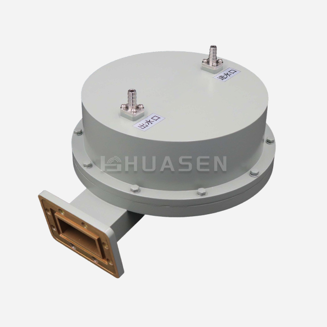
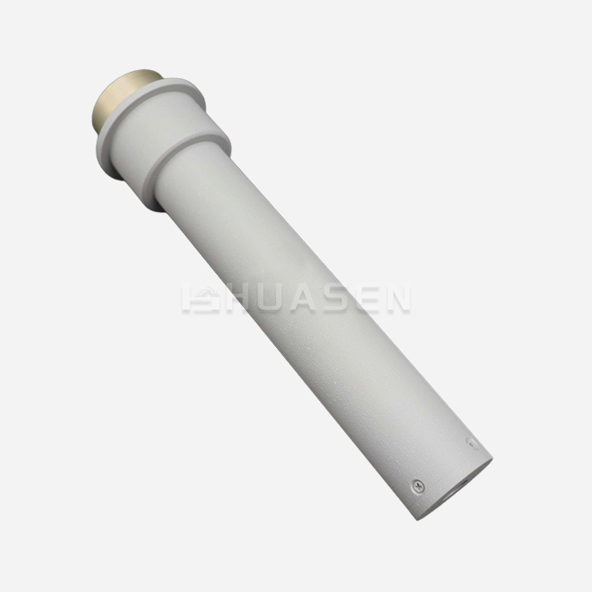
How does a waveguide power divider achieve microwave signal division?






2019-02-09 09:11:03
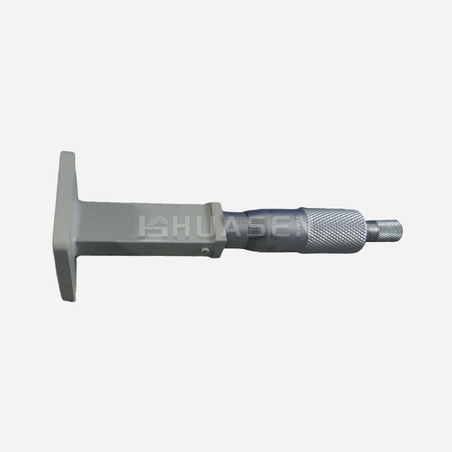
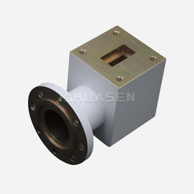
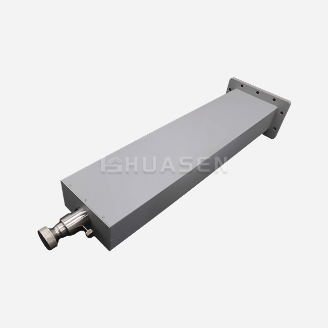
In microwave systems, a waveguide power divider is an important part that lets you split and distribute signals very accurately. These devices use electromagnetic principles to break up incoming microwave radiation into several output ports, each with its own phase and amplitude relationship. Engineers can make several splitting configurations, such as equal-split and unequal-split designs, by changing the waveguide's interior shape. The divider's structure typically incorporates carefully designed junctions, septa, or coupling slots that interact with the electromagnetic field to achieve the desired power distribution. Waveguide power dividers are great for high-frequency purposes in telecommunications, radar systems, and aerospace technology because they keep the signal strong and cut down on losses. For complicated microwave networks to work, they need to be able to split signals with high accuracy and speed. This helps current sensing and communication systems construct beam-forming arrays, mix signals, and work with more than one channel at a time.
How does a waveguide power divider split energy with controlled phase and amplitude?
The process of splitting energy in a waveguide power divider involves intricate electromagnetic interactions within the device's structure. To achieve controlled phase and amplitude division, several key mechanisms are employed:
Field Manipulation and Mode Coupling
Waveguide dividers utilize precise geometrical configurations to manipulate the electromagnetic field distribution. The gadget may stimulate certain waveguide modes and control their propagation by adding discontinuities like septa or coupling apertures. This mode coupling allows for the redistribution of energy between different output ports.
Impedance Matching
Maintaining proper impedance matching throughout the divider is crucial for minimizing reflections and ensuring efficient power transfer. Engineers make impedance transformers and matching sections to make the switch between the input and output ports as smooth as possible. This cuts down on signal loss and makes the system work better overall.
Phase Control Techniques
To achieve the desired phase relationships between output signals, waveguide dividers incorporate phase-shifting elements. These can include varying waveguide lengths, dielectric inserts, or specialized phase-shifting sections. Designers may make accurate phase changes across output ports by carefully modifying these parts. This is important for things like phased array antennas.
Amplitude Control Mechanisms
Controlling the amplitude of divided signals is accomplished through strategic power coupling and attenuation. This can involve adjusting the dimensions of coupling slots, implementing variable coupling structures, or incorporating attenuators within the divider. These techniques allow for the creation of both equal-split and custom ratio power dividers to meet specific system requirements.
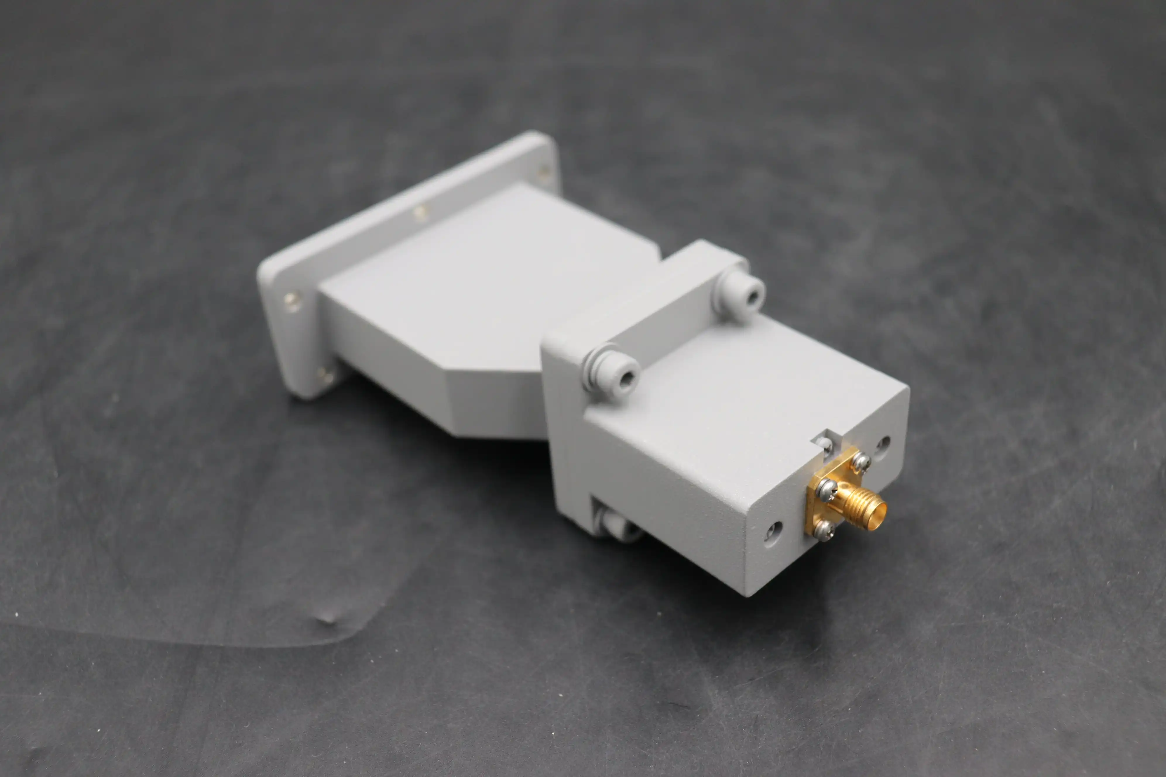
E-plane / H-plane / hybrid divider types — short summary
Waveguide power dividers are classified into different types based on their splitting plane orientation and design characteristics. Understanding these types is essential for selecting the appropriate divider for specific applications:
E-plane Dividers
E-plane dividers split the signal along the plane parallel to the electric field in the waveguide. These dividers are recognized for being small and work very well at keeping phase coherence between output ports. In applications that need very accurate phase control, including phased array antennas and radar systems, E-plane dividers are typically utilized.
H-plane Dividers
H-plane dividers split the signal along the plane parallel to the magnetic field. These dividers typically offer wider bandwidth capabilities compared to E-plane designs. H-plane dividers are frequently employed in applications where broad frequency coverage is essential, such as wideband communication systems and test equipment.
Hybrid Dividers
Hybrid dividers combine aspects of both E-plane and H-plane designs to achieve specific performance characteristics. These dividers can offer advantages such as improved isolation between output ports, enhanced power handling capabilities, or optimized splitting ratios. Hybrid designs are often used in complex systems that require a balance of multiple performance parameters.
Comparison and Selection Criteria
When choosing between E-plane, H-plane, or hybrid dividers, engineers consider factors such as:
- Frequency range and bandwidth requirements
- Power handling capabilities
- Phase and amplitude balance specifications
- Isolation between output ports
- Physical size constraints
- Thermal management considerations
The selection of the appropriate divider type depends on the specific needs of the application, balancing performance requirements with design constraints.
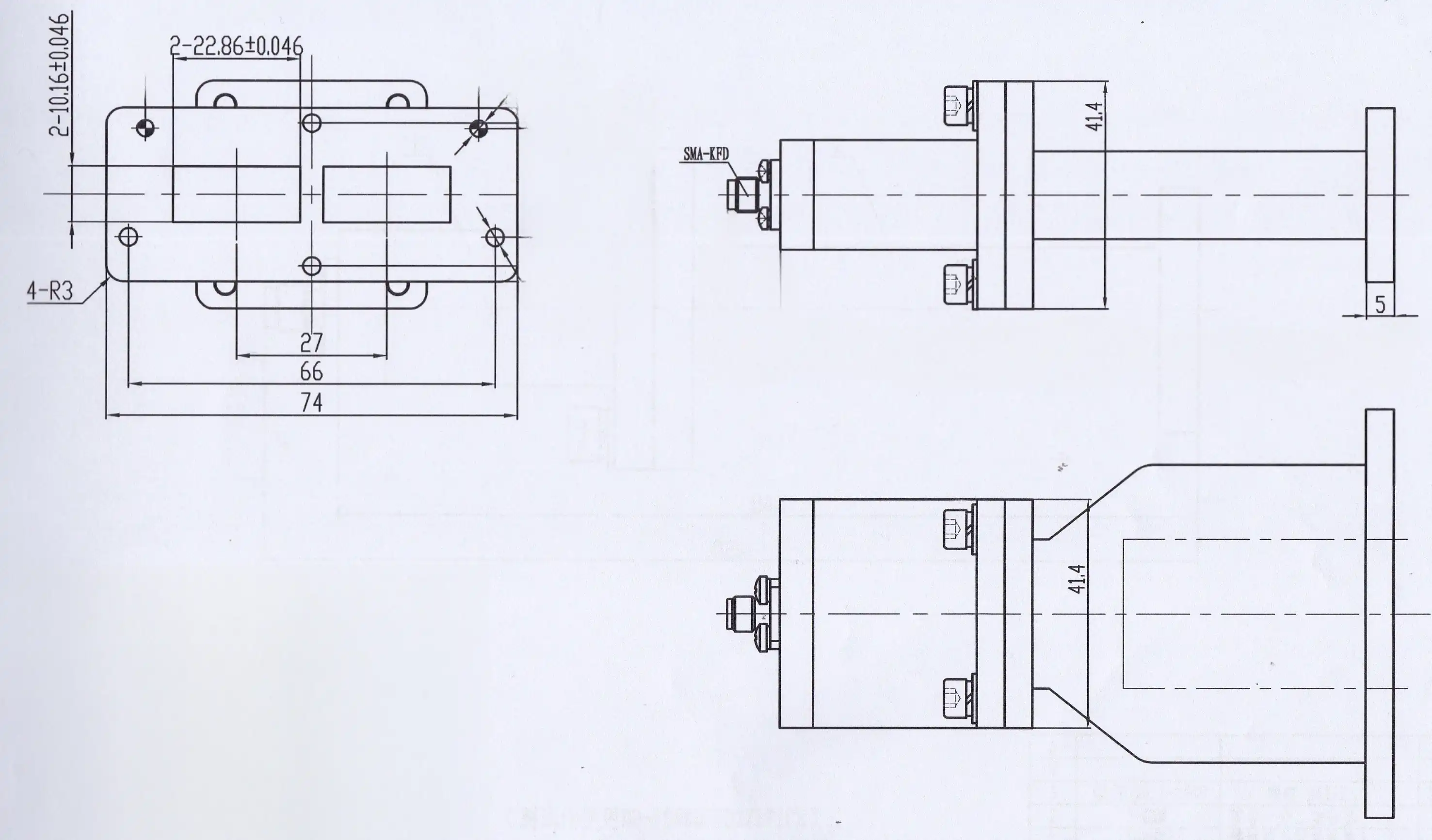
Common implementations: septum, T-junction, and slot/branch multiport dividers
Waveguide power dividers come in various implementations, each offering unique advantages for specific applications. Let's explore some of the most common types:
Septum Dividers
Septum dividers utilize a thin metal plate (septum) inserted into the waveguide to split the signal. Key features include:
- Excellent phase balance between output ports
- Compact design suitable for space-constrained applications
- Ability to achieve unequal power division by adjusting the septum position
- Typically used in E-plane configurations
Septum dividers are often employed in radar systems and phased array antennas where precise phase control is crucial.
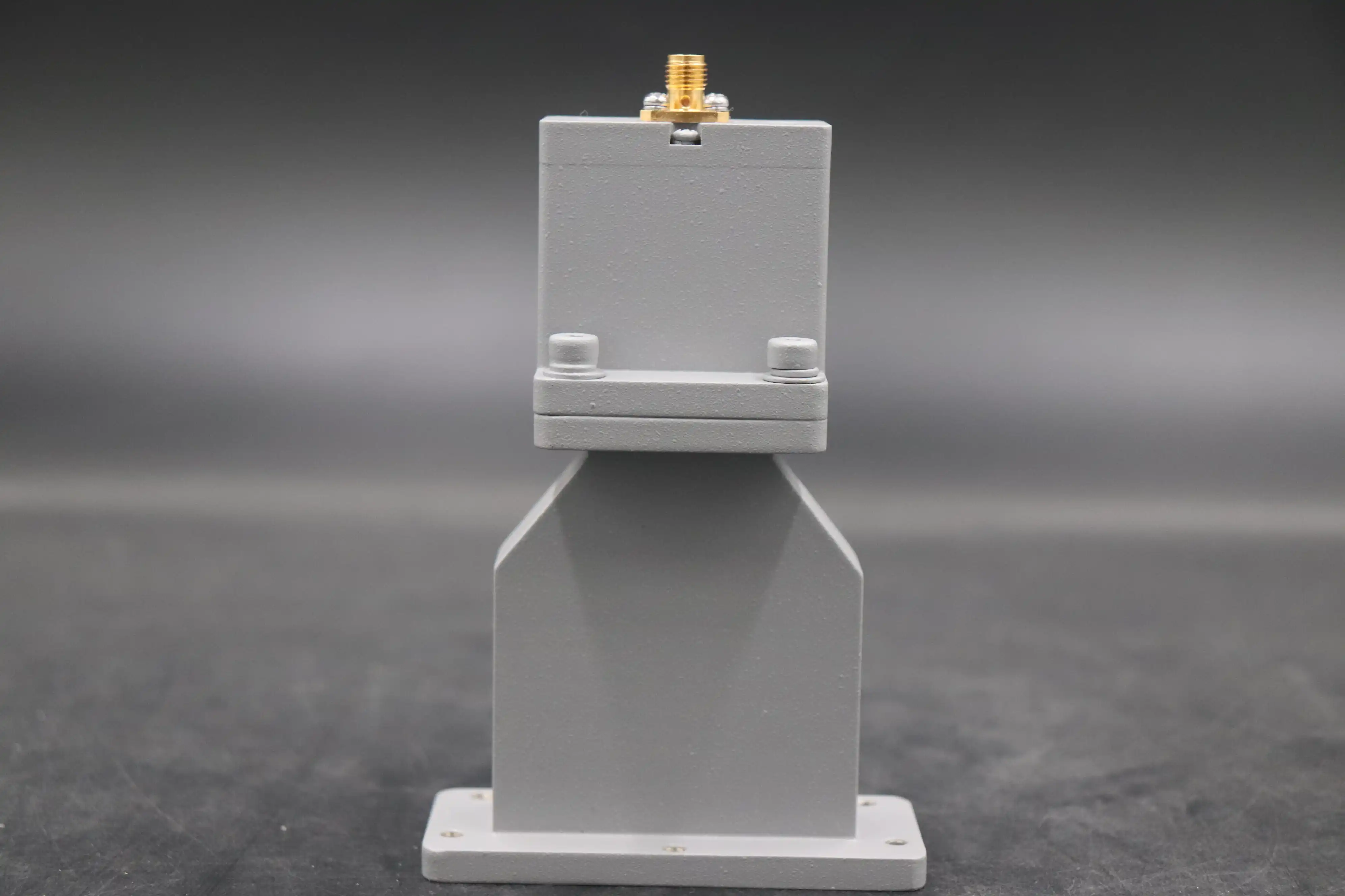
T-junction Dividers
T-junction dividers split the signal using a simple T-shaped waveguide intersection. Characteristics include:
- Straightforward design and ease of manufacture
- Good power handling capabilities
- Available in both E-plane and H-plane configurations
- Can be cascaded for multiple output ports
T-junction dividers are versatile and find applications in various microwave systems, from communication networks to test equipment.
Slot/Branch Multiport Dividers
These dividers use coupling slots or branching waveguides to split the signal into multiple outputs. Features include:
- Ability to create complex splitting networks with numerous output ports
- Flexible power distribution ratios
- Can be designed for high isolation between outputs
- Suitable for creating corporate feed networks in antenna arrays
Slot and branch dividers are essential in applications requiring multiple output channels, such as beam-forming networks and multi-element antenna systems.
Implementation Considerations
When implementing these divider types, engineers must consider:
- Impedance matching to minimize reflections and losses
- Bandwidth requirements and frequency response
- Power handling limitations, especially for high-power applications
- Manufacturing tolerances and their impact on performance
- Integration with other system components
Each implementation offers unique trade-offs between performance, size, and complexity. The choice depends on the specific requirements of the microwave system being designed.
Conclusion
Waveguide power dividers are essential parts of current microwave systems. For current telecommunications, radar, and aerospace uses, it's vitally important that they can differentiate signals very well. Engineers can adjust the way these devices are built to fulfill certain performance objectives by using different design methods, such as septum, T-junction, and multiport designs. Waveguide power dividers are becoming more and more important for making cutting-edge technology work as the need for high-frequency, high-power microwave solutions grows.
For those seeking high-performance waveguide power dividers tailored to their unique application needs, Huasen Microwave Technology Co., Ltd. stands ready to assist. Our team of skilled experts has been working with RF and microwave technologies for over 30 years. They can make custom dividers that fit even the most strict requirements. Our precision-engineered parts can assist in improving the performance of your system, whether you're building the next generation of 5G infrastructure, advanced radar systems, or satellite communication equipment. Call our technical support staff today to learn more about how our waveguide power dividers may improve your microwave applications and help your industry come up with new ideas.
FAQ
1. What frequency ranges do waveguide power dividers typically cover?
Waveguide power dividers can cover a wide range of frequencies, typically from 0.32 GHz to 112 GHz. The specific frequency range depends on the waveguide dimensions and design. Different waveguide sizes are used for different frequency bands, ensuring optimal performance across the microwave and millimeter-wave spectrum.
2. How does the power handling capability of waveguide power dividers compare to other types of power dividers?
Waveguide power dividers generally offer superior power handling capabilities compared to coaxial or stripline dividers. They can typically handle average powers of 200W or more, with peak powers reaching 2KW or higher. This makes them ideal for high-power applications in radar systems and industrial microwave equipment.
3. Can waveguide power dividers be customized for specific applications?
Yes, waveguide power dividers can be highly customized. Manufacturers can tailor aspects such as the power splitting ratios, connector types, and overall dimensions to meet specific application requirements. Custom designs can also incorporate features like integrated phase shifters or attenuators for more complex signal distribution needs.
4. What are the key performance parameters to consider when selecting a waveguide power divider?
When selecting a waveguide power divider, key parameters to consider include: - Frequency range and bandwidth - Insertion loss and amplitude balance - Phase balance between output ports - VSWR (Voltage Standing Wave Ratio) - Isolation between output ports - Power handling capacity - Size and weight constraints - Environmental specifications (temperature range, humidity resistance, etc.)
Elevate Your Microwave Systems with Precision-Engineered Waveguide Power Dividers | Huasen Microwave
Ready to enhance your microwave applications with high-performance waveguide power dividers? Huasen Microwave Technology Co., Ltd. offers a comprehensive range of standard and custom solutions to meet your specific needs. Our expert team is committed to delivering components that excel in power handling, precision, and reliability. Whether you're working on advanced telecommunications infrastructure, cutting-edge radar systems, or aerospace projects, we have the expertise to support your innovation.
Don't settle for off-the-shelf components that might compromise your system's performance. Contact us today at sales@huasenmicrowave.com to discuss your project requirements and discover how our waveguide power dividers can optimize your microwave system design. Let's collaborate to push the boundaries of what's possible in RF and microwave technology.
References
1. Johnson, R. C., & Jasik, H. (2018). Antenna Engineering Handbook. McGraw-Hill Education.
2. Pozar, D. M. (2011). Microwave Engineering. John Wiley & Sons.
3. Uher, J., Bornemann, J., & Rosenberg, U. (2013). Waveguide Components for Antenna Feed Systems: Theory and CAD. Artech House.
4. Collin, R. E. (2001). Foundations for Microwave Engineering. John Wiley & Sons.
5. Marcuvitz, N. (1951). Waveguide Handbook. IET.
6. Skolnik, M. I. (2008). Radar Handbook. McGraw-Hill Education.
Send Inquiry