Quadridged Horn Antenna Behavior in Extreme Frequency Environments






2026-07-13 17:04:30
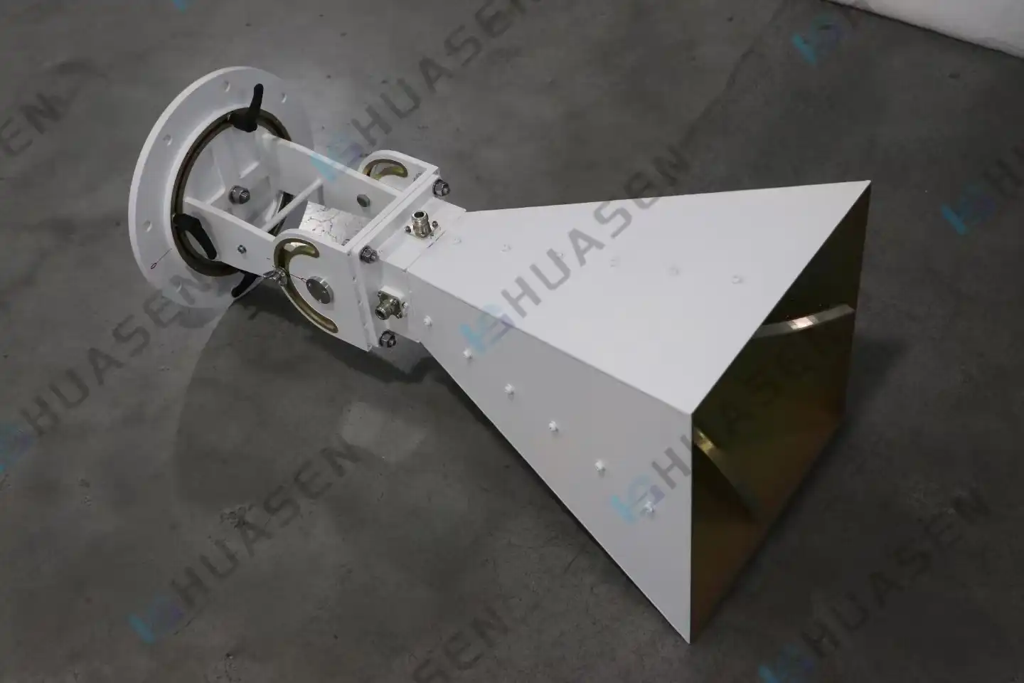
The Quadridged Horn Antenna is very stable and flexible when it comes to working across very wide frequency ranges, from sub-GHz ranges to 40 GHz and beyond. This unique aperture antenna has four equally placed metallic ridges inside a curved waveguide structure. This allows for consistent impedance matching and dual-polarization across many octave bandwidths. In places like EMC testing laboratories, radar calibration laboratories, and satellite communication ground stations where frequency extremes make regular antenna designs hard to use, engineers rely on these devices. Procurement teams that are in charge of setting up next-generation wireless infrastructure need to know how these antennas keep the signal strong in such harsh conditions.
Understanding Quadridged Horn Antennas in Extreme Frequency Conditions
Dual-polarized horn antennas are built in a way that gets around some of the major problems that come with single-ridge or standard pyramidal designs. Precise ridge shape is at the heart of this technology. From the throat to the aperture, four ridges stretch, creating controlled capacitive loading that widens the working bandwidth much more than standard horns can.
Structural Design Enabling Ultra-Wideband Performance
The curved ridge shape changes the waveguide's characteristic resistance slowly, which reduces reflections over a frequency range of 10:1 or more. This continuous impedance transformation is different from narrowband resonant antennas in that it lets a single unit replace many frequency-specific devices. We've seen this design principle work wonders when system integrators combine their test equipment inventories, cutting down on both capital costs and the time needed to calibrate the equipment.
The choice of material is also very important. Aluminum or copper bodies with high conductivity keep insertion loss low, and precise machining tolerances—often within micrometers at ridge tips—make sure that high-frequency behavior is reliable. The aperture sizes get smaller as the lowest operating frequency goes down. This means that structures need to be a lot bigger for a 1 GHz lower bound than for an 18 GHz design.
Radiation Patterns and Polarization Control
Each of the four ridges is linked to its own separate feed networks that support linear polarizations that are orthogonal to each other. This two-port design lets you receive both horizontal and vertical E-fields at the same time without having to mechanically rotate the device. Isolation between ports is usually higher than 25 dB, which stops crosstalk that could mess up vector measurements in antenna test ranges.
The patterns of radiation are moderately directed, and the gain goes from about 5 dBi at lower frequencies to 19 dBi at the top of the band. Beamwidth stays mostly the same, but there are small changes that depend on frequency because the electrical aperture size changes. When made correctly, cross-polarization discrimination (a key metric for measuring radar cross-section) stays below -20 dB for most of the operating spectrum.
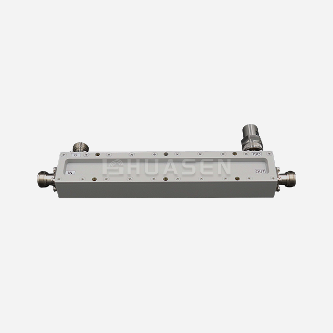
Outside parts are needed for the change from linear to circular polarization in a quad-ridged horn antenna. When you connect a broadband 90-degree hybrid coupler, it creates the phase offset needed for LHCP or RHCP generation. This makes the coupler more useful in satellite ground stations and for checking EMI protection according to CISPR standards.
Key Performance Factors and Optimization Strategies
Understanding how electrical parameters and physical limits affect each other is key to successful deployment in environments with very high frequencies. We look at specification from three points of view: the quality of the impedance matching, the amount of power it can handle, and how well it can handle the environment. Well-designed Quadridged Horn Antennas keep VSWR below 2.0:1 across their whole bandwidth, and high-end models get 1.5:1 or better in tuned sub-bands.
Critical Electrical Metrics
The Voltage Standing Wave Ratio (VSWR) measures how well two impedance matches work. This directly leads to less signal reflection and better transmission efficiency, which are very important factors when describing low-noise amplifiers or checking antenna factors to meet regulatory requirements.
| Parameter | Specification Range | Impact on System Performance |
|---|---|---|
| VSWR | 1.5:1 to 2.5:1 | Determines reflection loss; lower values improve measurement accuracy |
| Port Isolation | >25 dB (typical >30 dB) | Prevents crosstalk between polarizations; critical for dual-pol measurements |
| Gain (Frequency-Dependent) | 5-19 dBi | Higher gain concentrates radiated energy; scales with frequency |
| Continuous Power Handling | 50-500W | Limited by connector type and ridge gap; affects immunity test capabilities |
| Operating Temperature | -40°C to +70°C | Defines environmental suitability for outdoor/aerospace applications |
Gaining flatness over decades of bandwidth is hard to do in a quad-ridged horn antenna in its own way. While the wavelength changes by 10:1 or more, the size of the electrical aperture stays the same. This creates an inherent gain slope. Some methods for compensation are better flare angles and ridge-narrowing shapes that are created through electromagnetic simulations and checked in rooms with no sound.
Optimisation Through Design and Materials
To minimise frequency-dependent phase centre shift, you have to balance different electromagnetic forces. We discovered that smooth changes in both ridge height and horn flare rate lower dispersion effects that hurt the accuracy of time-domain pulses. This is very important for calibrating radar and testing ultra-wideband communications, since changes in group delay can distort signal waveforms.
Two things limit the amount of power that can be handled: the current capacity of the connectors and the air breakdown voltage at the ridge gaps. Because of the small space needed for high-frequency function, electric fields become concentrated, which could cause corona discharge. For high-power immunity testing situations with waves that go over 100W continuously, premium versions have smooth ridge edges and pressurised gas fills.
Environmental durability goes beyond what is required by electrical standards. When installations are outside, they have to deal with getting wet, changing temperatures, and mechanical vibrations. Conformal coatings keep the insides from rusting, and strong mounting hardware, which usually has six-axis adjustment mechanisms, keeps the alignment exact even when the wind blows or when ships and planes move the platforms.
Managing heat is very important in active electronically scanned arrays with many quad-ridged horn antenna elements working together in close quarters. Paths for heat to escape must stop temperature differences that change the dielectric properties or cause the metal to warp. We choose materials with matched thermal expansion coefficients so that they stay the same size from -40°C to +85°C, which is what MIL-STD-810 requires.
Comparative Insights: Quadridged Horn Antenna vs. Alternative Antenna Types
When making decisions about what to buy, it helps to know where Quadridged Horn Antenna technology shines compared to other options. Because of basic physics and manufacturing limitations, each type of antenna has its own set of pros and cons.
Performance Trade-Offs Across Technologies
Log-periodic arrays cover similar bandwidths, but they lose gain and add a lot of backlobe radiation. Their printed-circuit design makes them light enough to use on airborne platforms where space constraints limit options. However, the multiple resonant elements create complicated impedance patterns that make precise calibration difficult. We suggest log-periodics when size and weight are more important than gain needs, like when electronic warfare pods are placed on drones.
When built with enough cone size, biconical antennas can hit frequencies lower than 100 MHz, which is lower than horn designs. The omnidirectional pattern works well for broadcasting, but it doesn't have the directionality needed for point-to-point links or focused lighting in small antenna test ranges. When compared to ridge-guided structures, the ability to separate orthogonal polarisations also gets worse.
Patch and microstrip arrays can be made in small sizes that make them useful for integrated systems and phased arrays. But without complicated layered feeding networks, bandwidth rarely goes above 20–30%. More importantly, they have trouble handling power—normal patch elements get too hot around 1–5W, which means they can't be used for immune testing or high-power radar simulations that need hundreds of watts.
| Antenna Type | Bandwidth Ratio | Typical Gain | Polarization | Best Application |
|---|---|---|---|---|
| Quadridged Horn | 10:1 or greater | 5-19 dBi | Dual-linear/CP capable | EMC testing, wideband radar calibration, satellite ground stations |
| Log-Periodic | 10:1 | 4-10 dBi | Single linear | Direction finding, wideband monitoring, and UAV installations |
| Biconical | 10:1 | 2-5 dBi | Linear (omnidirectional) | Broadcast, radiated emissions testing, low-frequency EMI |
| Patch Array | 1.3:1 | 6-12 dBi | Single/dual (narrow band) | Embedded 5G/6G, compact phased arrays, cost-sensitive applications |
| Pyramidal Horn | 1.5:1 | 10-25 dBi | Single linear | Waveguide feeds, high-precision gain standards, and narrow frequency spans |
Standard pyramidal horns have better gain and pattern purity, but they only let you use them in a few frequency ranges. For a full 2-40 GHz test capability, you would need at least eight different horn antennas, and each one would need to be calibrated and stored separately. This is broken down into two or three units that cover overlapping bands with continuous performance in the quadridged architecture.
Application-Specific Selection Criteria
In commercial EMC labs, Quadridged Horn Antenna decisions are based on how well the chamber is used. It can take 12 to 16 hours for each device to go through test routines that include emission sweeps and immunity testing across multiple polarizations. Dual-polarization capability greatly shortens this time frame by removing the need for mechanically rotating antennas and rearranging cables between polarization states.
Satellite telemetry reception needs a high signal-to-noise ratio, which favors higher-gain solutions. Even though quad-ridged horns don't have a lot of directivity, their pattern stability is better than that of electronically steered options, which can experience phase shifter drift. This predictable RF behavior is helpful for maritime communication terminals that work in both tropical and arctic conditions.
Procurement Guide: Sourcing and Selecting Quadridged Horn Antennas
To get through the B2B sourcing process, you have to balance technical requirements with delivery schedules, budgets, and long-term support obligations. We organize buying into three steps: defining needs, evaluating suppliers, and analyzing lifecycle costs.
Specification Development
Setting working settings starts with figuring out the frequency range. "Broader is better" makes sense, but designs with very wide bands lose out on optimization. In that case, a 2-18 GHz unit designed for radar cross-section work might work better than a 1-40 GHz general-purpose antenna. By matching bandwidth to actual system needs, you can avoid paying too much for capacity that isn't being used.
The VSWR limits are set by the measuring error budgets. While standard pre-compliance EMC scans can handle 2.5:1, accredited laboratory work usually needs 1.8:1 or tighter to meet ISO 17025 traceability standards. We need full S-parameter datasets, not just normal curves, to check the performance of each unit before acceptance testing.
Choosing the right connector has an effect on both the electrical and mechanical integration. Precision 2.92 mm or K-connectors let you work up to 40 GHz, but they only let you use about 50 W of power. On the other hand, 7/16 DIN or N-type connectors can handle hundreds of watts but can't go above 18 GHz. Multiple connector choices are built into hybrid designs through internal changes. This adds cost and creates a chance for failure spots.
Supplier Assessment and Quality Assurance
Manufacturers you can trust give you individual calibration certificates that can be tracked back to national metrology institutes. These papers explain how to measure antenna factors, gain, and VSWR at certain frequencies using the Three-Antenna Method or Standard Site procedures in line with ANSI C63.5 rules. We carefully read calibration uncertainty claims; numbers greater than ±1 dB make us wonder about the powers of the measurement site.
Because mechanical errors are so small, production accuracy is very important. Even though ISO 9001 certification means that the process is being controlled, we still want to know how often manufacturers check the ridge gap dimensions while the product is being made. What statistical process control methods are used to run machining? Premium suppliers are different from commodity suppliers because they use laser scanning and coordinate measuring machines to check important geometries.
Lead times show how complicated the manufacturing process is and how mature the supply chain is. Catalogue items usually ship between 2 and 4 weeks, but it can take up to 12 weeks for custom frequency splits or special mounting brackets. Talking about expedited choices up front keeps the project from being held up when testing the prototype shows that it needs more quad-ridged horn antennas than thought.
Customization and After-Sales Support
Custom solutions solve installation problems that can't be solved by products from a catalog. We've asked for different aperture sizes for airplane fairings that are limited on space, coatings that are more resistant to rust on ships, and antennas that are protected by built-in radomes in bad weather. Manufacturers who offer 3D modeling, teamwork, and sample versions show that they care about their customers in more ways than just a business sense.
The level of technical help is clear during the pre-sales phase. Do the application engineers you work with understand how you plan to measure things? Can they tell me the best way to mount things and route cables so that pattern distortion is kept to a minimum? It is possible to make correct link budget estimates and characterize chamber quiet zones when you have access to detailed pattern cuts, not just main plane data.
Because these quad-ridged horn antennas are used in harsh environments, it's important to pay attention to the warranty terms and repair options. Damage from drops to ridge structures or water getting in through connector seals can slowly lower performance. We'd rather have suppliers keep calibration and repair services in the United States than require international shipments that cause downtime to last longer.
Conclusion
In order to work in places with very high or very low frequencies, antennas need to be able to keep their electrical stability over very wide ranges of frequencies while also being able to handle high levels of power, pressure, and temperature. This is possible with Quadridged Horn Antenna technology, which has precise ridge geometry, a strong mechanical design, and the ability to work with both positive and negative polarization, which makes complicated measurement workflows easier to handle. It's helpful for procurement teams to know the pros and cons of bandwidth, gain, and power handling, as these specs have a direct effect on test throughput, measurement uncertainty, and lifecycle costs. When choosing the right dual-polarized horn antenna for EMC labs, radar calibration ranges, or satellite ground networks, it's important to match the technical specs to the operational scenarios and work with suppliers who offer traceable calibration and quick engineering support.
FAQ
1. What frequency ranges do quadridged horn antennas typically cover?
The frequency range of modern designs is from 0.1 GHz to 40 GHz, with different models focusing on different sub-ranges. Ultrawideband versions, like the DPHA series, can cover many decades with a single unit, which means they can replace a number of narrowband horns. For frequencies below 1 GHz, apertures that are close to one meter are needed, but millimeter-wave designs can work well up to Ka-band.
2. How does dual-polarization capability benefit EMC testing workflows?
When horizontal and vertical fields are measured at the same time, Quadridged Horn Antennas don't have to be rotated, and wires don't have to be reconnected between polarization states. In most automotive or aerospace compliance programs, this cuts the time it takes to test for radiated emissions by 40 to 50 percent. When checking for immunity, fast polarization switching is also helpful because it finds equipment flaws more quickly than sequential single-pole scans.
3. Can these antennas generate circular polarization?
Dual-linear polarization is made by the antenna itself. To get circular polarization, you need to add a 90-degree hybrid coupler that moves one port's phase relative to the other port. Based on IEC 61000 standards, this setup makes LHCP or RHCP that can be used for satellite transmission or EMI tests. The coupler, not the antenna, determines how much power it can handle and how wide its bandwidth can be.
Partner with Huasen Microwave for Reliable RF Solutions
Since 1993, Huasen Microwave has been designing ultra-wideband dual-polarized horn antennas. They do this by combining precise manufacturing with strict quality control to make parts that are used around the world in defense, aerospace, and telecommunications. Our DPHA and DPOBHA series cover frequencies from 0.1 GHz to 40 GHz and have port isolation of more than 30 dB. They also come with traceable calibration and six-axis mounting systems that make sure measurements are always the same. Our applications team works together to create custom solutions that meet your frequency, power, and environmental needs, whether you're expanding 5G test labs, improving radar cross-section facilities, or setting up satellite ground terminals.
As a top Quadridged Horn Antenna manufacturer, we keep a large inventory on hand so that we can deliver quickly. We also offer custom designs that are made to fit your exact needs. Email our technical experts at sales@huasenmicrowave.com to talk about the details of your project, get calibration datasheets, or set up sample trials. We want to help you improve your RF skills by providing quick support and dependability that has been tested in the field.
References
1. Balanis, Constantine A. Antenna Theory: Analysis and Design. 4th ed. Wiley, 2016.
2. IEEE Standard 149-2021. IEEE Standard for Antenna Measurements. Institute of Electrical and Electronics Engineers, 2021.
3. Kerr, J. L. "Short Axial Length Broad-Band Horns." IEEE Transactions on Antennas and Propagation vol. 21, no. 5, 1973, pp. 710-714.
4. European Telecommunications Standards Institute. ETSI EN 300 386: Telecommunication Equipment – Electromagnetic Compatibility Requirements. ETSI, 2020.
5. Pozar, David M. Microwave Engineering. 4th ed. Wiley, 2011.
6. U.S. Department of Defense. MIL-STD-461G: Requirements for the Control of Electromagnetic Interference Characteristics of Subsystems and Equipment. 2015.
Send Inquiry