Power Amplifier Applications in Radar and Satellite Networks






2026-07-14 16:57:45
These days, the most important part of radar and satellite transmission devices is the power booster. Radio frequency (RF) signals that aren't very strong are turned into high-power signals that can reach targets thousands of miles away. These specialised devices are not at all like regular audio amplifiers. They work at radio frequencies from MHz to GHz and can handle complex modulation schemes while still meeting strict standards for efficiency and linearity. Power amplifiers give radars the small bursts of power they need to find their targets. In satellite launch stations, signals are boosted to get around the huge loss of signal quality that happens when data is sent through space.
Understanding Power Amplifiers in Radar and Satellite Systems
The main job of an RF power amplifier is to boost signal strength without distorting it in a way that would damage data security. Unlike audio amplifiers that are meant to play sound, these devices work in difficult electromagnetic settings where maintaining stable temperatures, removing harmonics, and fine-tuning gain are crucial to their success.
Basic Operation and Amplifier Classes
Power amplifiers used in high-frequency situations have different design principles depending on the class they are in. When it comes to precision radar systems, where target resolution depends on waveform fidelity, Class A power amplifiers are essential because they conduct continuously throughout the signal cycle and offer excellent linearity with minimal harmonic distortion. But their efficiency rarely goes above 30%, which makes a lot of heat, making it harder to control the temperature in satellite transponders.
Class AB designs are a good compromise because they let the current flow through most of the waveform while still allowing short cutoff periods. This solution gets the efficiency up to 70% while keeping the distortion levels low enough for most transmission satellites that use C-band and Ku-band frequencies. Modern phased array radars are using Class D switching architectures more and more. These get efficiency levels above 85% by using pulse-width modulation. Switching noise can be a problem, but advanced filtering methods can help in situations where speed is more important than spectral clarity.
Impedance Matching and Signal Integrity
The performance of a power amplifier in the real world depends on how well its impedance is matched throughout the RF chain. When impedances aren't aligned, standing waves are made. These waves lower the amount of power that can be transferred, raise the voltage standing wave ratio (VSWR), and can hurt semiconductor junctions when they are under a lot of power. Most commercial and military systems have standard characteristic impedances of 50 ohms, but some specialised radar applications use 75-ohm architectures.
| Parameter | Typical Radar Specification | Satellite Uplink Specification |
|---|---|---|
| Frequency Range | 2-18 GHz (X-band typical) | 5.925-6.425 GHz (C-band) / 14.0-14.5 GHz (Ku-band) |
| Output Power | 100W-10kW (pulsed) | 50W-500W (continuous) |
| Gain | 40-60 dB | 50-70 dB |
| Efficiency | 30-60% (Class AB/D) | 40-55% (Class AB typical) |
| Linearity (IMD3) | -25 to -35 dBc | -30 to -40 dBc |
When connecting equipment from different vendors, which may use different connector standards, the problem gets worse. The RF coaxial adapters from Huasen Microwave solve this problem by making it easy to switch between N-type, SMA-type, and 2.92 mm connections. These precision adapters keep a wide frequency range covered with little signal loss. This makes sure that changes in impedance don't mess up the carefully planned power amplifier stages. When it comes to radar front-ends, where every 0.1 dB of insertion loss directly means a shorter detection range, their low standing wave ratio is very useful.
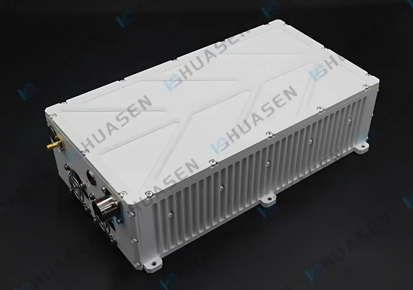
Key Applications of Power Amplifiers in Radar and Satellite Networks
From ground-based monitoring radar to geostationary satellite transponders, modern defence and communication systems rely on power amplifiers that are specially designed to meet their needs.
Radar Signal Generation and Transmission
Ground-based air monitoring radars are a good example of a tough setting where power amplifiers need to give bursts with kilowatt levels and rise times of microseconds. The power amplifier has to go from being idle to full power in a matter of nanoseconds, keep its frequency response flat across a wide range of immediate bandwidths, and handle the heat stress that comes from repeated pulses. Modern radar uses pulse compression methods that put extra stress on phase linearity. Any phase error that depends on amplitude lowers range precision and raises sidelobe levels, which makes weak targets near strong reflections harder to see.
When naval radar systems are used in maritime environments, they have to deal with corrosion from salt spray, temperature changes from tropical to arctic, and shock loads from firing weapons. Solid-state power amplifiers made with gallium nitride (GaN) semiconductor technology are more durable than older travelling wave tube power amplifiers. In well-designed systems, the average time between breakdowns is more than 100,000 hours.
Satellite Communication Uplink Amplification
At Ku-band frequencies, geostationary communication satellites create a free-space path loss of about 200 dB 35,786 kilometres above the equator. To get around this loss, earth station power amplifiers must send hundreds of watts to high-gain parabolic antennas. In contrast to radar applications, satellite uplinks work all the time, putting constant thermal stress on semiconductor junctions and passive cooling systems.
Modern satellite operators use higher-order modulation schemes like 16APSK and 32APSK to get more data into a limited amount of receiver bandwidth. However, these schemes need very good stability from the power amplifier. Third-order intermodulation distortion must stay below -30 dBc to keep adjacent channel interference from happening, which would be against ITU rules and hurt the quality of service for satellite operators nearby.
Emerging Applications in Phased Arrays and Software-Defined Systems
By electrically directing beams without moving any parts, phased array antennas change the way radar and satellite communications work. Each element in an array needs its own power amplifier, so there is a need for small, efficient devices that can work in tight spaces. As more and more power amplifiers are added, heat builds up in small areas, making thermal management even more important. To keep junction temperatures within safe working limits, new cooling methods are needed.
Software-defined satellites are the newest development in space communications. They have payload architectures that can be changed so that coverage patterns and frequency allocations can be changed to meet changing demand. Power amplifiers with a large instantaneous bandwidth and fast gain control are needed for these systems. This lets them dynamically assign resources in a way that makes the most money per kilogram of launched mass.
How to Choose the Right Power Amplifier for Radar and Satellite Applications?
When making a buy choice, you have to think about technology specs, the supply chain, and how to provide long-term help that goes beyond the original purchase price.
Defining Technical Requirements
Before looking at what suppliers have to offer, system engineers need to set clear performance standards. Link budget calculations figure out how much output power is needed by taking into account antenna gain, atmospheric losses, and the receiver's signal-to-noise ratio needs. In radar applications, the peak envelope power for pulsed operation is usually given, while in satellite uplinks, the average power over the carrier duty cycle is given.
Losses in the transmission chain must be taken into account in the gain specs. These losses can be caused by waveguide runs, circulators, and radome attenuation. When gain is too high, money is wasted on performance that isn't needed, and when gain is too low, upstream parts have to work at higher drive levels, which hurts continuity. Efficiency has a direct effect on running costs because it affects how much power is used and how much cooling is needed. For example, a 10% improvement in the efficiency of a 1 kW power amplifier cuts heat loss by 100 watts, which could mean that forced-air cooling is not needed.
| Connector Type | Frequency Range | Typical VSWR | Common Applications |
|---|---|---|---|
| N-Type | DC-18 GHz | <1.15:1 | Base station links, radar feeds |
| SMA | DC-26.5 GHz | <1.20:1 | Test equipment, satellite ground stations |
| 2.92mm (K) | DC-40 GHz | <1.25:1 | Millimetre-wave radar, 5G backhaul |
Evaluating Suppliers and Total Cost of Ownership
A brand's image is a good way to lower risk, especially for companies that don't have their own RF experts to check performance claims. Well-known companies spend money on testing their products to meet military standards like MIL-STD-810 for durability in harsh environments and MIL-STD-461 for electromagnetic compatibility. These certifications are really valuable; they show that you care about quality beyond just marketing words and are based on thousands of hours of engineering work.
Warranty coverage shows that the company that made the product trusts it to work well. In a lab, a standard one-year warranty is enough, but for practical systems, longer coverage is needed to protect against early breakdowns during the crucial early rollout phase. It's just as important that the supplier be able to provide field-replaceable modules, stock spare parts locally, and send technical experts to troubleshoot on-site.
Logistics costs must be included in the total cost of ownership calculations. This is especially true for foreign purchases, where customs processing, shipping insurance, and import taxes add a lot to the billing price. Companies with more than one location can save money by sticking to a few families of RF power amplifier products. This cuts down on the need for spare parts and training for maintenance teams.
Optimising Performance and Reliability in Power Amplifiers for Radar and Satellite Systems
Achieving the required performance in the lab is only the beginning. For long-term operation in real-world settings, you need to pay attention to thermal management, protection circuits, and regular maintenance.
Thermal Management and Signal Distortion Solutions
It is normal for semiconductor performance to get worse as junction temperature rises. Output power goes down, efficiency goes down, and distortion goes up. Keeping junction temperatures below 150°C is necessary for safe operation, but it's hard to get heat out of power amplifier units that are closely packed together using normal cooling methods. For installations on the ground that don't have to worry about weight, conduction cooling through metal base plates works well. But for platforms in the air, they need lightweight heat pipes or liquid cooling loops.
Power amplifier nonlinearity shows up as spectral regrowth, which increases the signal's bandwidth and causes confusion in frequencies that are close by. Digital predistortion techniques stop this from happening by purposely distorting the input signal in the opposite direction. This makes the power amplifier's nonlinearities go away, leaving only linear output. Modern predistortion algorithms are always changing to account for changes in temperature and worn-out parts, so they keep their distortion performance over years of use.
Circuit Design Advances and Protection Mechanisms
New developments in the Class AB design use envelope tracking to change the drain voltage flexibly based on the signal intensity. This method stays very effective even when the power level changes. This is especially helpful for satellite communications, where traffic loads change throughout the day. When the output is at its highest, efficiency is at its highest. Even when the output is lowered by 6 dB, efficiency still stays at 40%, compared to 25% for traditional fixed-voltage designs.
Protecting power amplifiers from faults that could otherwise cause them to fail catastrophically is what protection circuits do. Output mismatch detectors pick up on reflected power and cut the drive right away if VSWR goes over safe limits. This keeps voltage from dropping in output matching networks. Temperature monitors built into the semiconductor die stop the heating process before the junction temperatures get too high and damage it. In microseconds, over-current limiters respond to arcing or short circuits, which is faster than external circuit breakers.
Deployments in the real world show how useful these safety steps are. In the North Atlantic, salt fog builds up around a coastal surveillance radar station, breaking down antenna feedline insulation over time. Over months of use, VSWR slowly rises. The RF power amplifier's safety circuits keep it from breaking and let repair staff know about the problem, so there is no unplanned downtime during storm season, when radar availability is most important.
Conclusion
Power amplifiers serve as critical enablers across radar and satellite networks, demanding careful selection based on frequency range, output power, linearity, and environmental durability. Understanding power amplifier classes, impedance matching requirements, and thermal management strategies allows procurement teams to evaluate supplier claims against operational requirements. The shift toward phased array architectures and software-defined systems introduces new demands for compact, efficient designs with adaptive capabilities. Successful procurement balances technical specifications with supply chain reliability, warranty coverage, and total cost of ownership. Organisations prioritising these factors deploy systems that deliver consistent performance throughout operational lifespans.
FAQ
1. What distinguishes RF power amplifiers from audio amplifiers in radar applications?
RF power amplifiers operate at radio frequencies from MHz to GHz ranges, handling electromagnetic waves rather than acoustic signals. These devices require specialised impedance matching, employ different semiconductor technologies (GaN and GaAs versus silicon), and must manage harmonic distortion across wide bandwidths. Radar Power Amplifiers generate high-power pulses with microsecond rise times—performance characteristics irrelevant to audio applications.
2. Why does Class AB technology benefit satellite communication uplinks?
Class AB power amplifiers balance efficiency and linearity requirements inherent in satellite communications. They achieve 50-70% power efficiency while maintaining the low distortion necessary for modern modulation schemes like 16APSK. This compromise reduces thermal management complexity compared to Class A designs while avoiding the switching noise challenges of Class D architectures in spectrum-constrained satellite bands.
3. What impedance matching considerations matter most during procurement?
Verify that power amplifier input/output impedances match system characteristic impedance (typically 50 ohms) to minimise VSWR and maximize power transfer. Confirm connector compatibility with existing infrastructure—mismatched connectors introduce discontinuities that degrade performance. Request VSWR specifications across the operating frequency range, as broadband power amplifiers may exhibit impedance variations at band edges. Huasen Microwave's precision adapters solve multi-connector environments by enabling seamless transitions between N-type, SMA, and 2.92mm standards with minimal signal degradation.
Partner with Huasen Microwave for Reliable Power Amplifier Solutions
Procurement professionals and system engineers seeking dependable components for radar and satellite networks will find comprehensive support at Huasen Microwave. As an established Power Amplifier supplier with over three decades of RF expertise, we deliver customised solutions addressing frequency coverage, power handling, and environmental durability requirements specific to your application. Our technical team assists with design integration, provides detailed test data, and maintains inventory for rapid delivery schedules. Contact us at sales@huasenmicrowave.com to discuss your project specifications, request performance documentation, or arrange a sample evaluation. We stand ready to support your mission-critical communications infrastructure with the reliability your operations demand.
References
1. Cripps, S. C. (2006). RF Power Amplifiers for Wireless Communications (2nd ed.). Artech House Publishers.
2. Grebennikov, A., Sokal, N. O., & Franco, M. J. (2012). Switchmode RF and Microwave Power Amplifiers (2nd ed.). Academic Press.
3. Pozar, D. M. (2011). Microwave Engineering (4th ed.). John Wiley & Sons.
4. Skolnik, M. I. (2008). Radar Handbook (3rd ed.). McGraw-Hill Education.
5. Maral, G., & Bousquet, M. (2009). Satellite Communications Systems: Systems, Techniques and Technology (5th ed.). John Wiley & Sons.
6. Kenington, P. B. (2000). High-Linearity RF Amplifier Design. Artech House Publishers.
Send Inquiry