Why Choose a Coaxial Directional Coupler for RF Networks?






2026-07-14 16:57:43
It is important to use the right signal tracking tool when planning or keeping RF networks for things like 5G base stations and aircraft radar systems. A coaxial directional coupler gives you the highest level of accuracy by sampling electromagnetic power moving in a specific direction without getting in the way of your main signal line. This passive device, unlike basic splitters, separates waves that come in and waves that come back. This lets you measure VSWR in real time, level power in amplifier loops, and control feedback, all while keeping low insertion loss and high directivity. This feature fixes important problems in the industry, like keeping signals strong, finding impedance mismatches, and making sure transmitters work the same way in harsh conditions.
Understanding Coaxial Directional Couplers: Theory and Functionality
Core Construction and Operating Principles
Directional couplers work by using electromagnetic coupling inside a precisely machined coaxial housing. These housings are usually made of aluminum or brass and are plated with silver or gold to reduce skin effect losses. The device has four ports: an input port, a through port (main line), a linked port, and an isolated port. As energy moves along the main line, it causes a proportional signal at the coupled port. On the other hand, reverse signals are blocked at the isolated port, which can be measured by directivity.
Transmission line theory is what the electromagnetic principle is based on. Phase-dependent interactions are made by coupled lines running parallel to each other inside the shielding structure. When set up correctly, forward waves combine in a good way at the coupled port, while reflected waves cancel each other out through destructive interference. Because it can separate signals, the device is essential for antenna matching networks and spectrum research.
Key Performance Parameters Explained
You can pick the best gadget if you know the specs. What does the coupling factor (dB) measure? It tells you how much power is sent to the coupled port. The usual range is from 10dB to 50dB. Directivity, which shows how well they separate forward signals from mirrored signals, can reach 20dB to 30dB for good couplers. It is less than 0.5 dB when coupling loss is taken into account, and it measures how much power is lost in the main line. If the VSWR is less than 1.25:1, there are almost no echoes at any port. This keeps the signal pure.
It can cover frequencies from 0.03 GHz to 40 GHz, depending on the design. This makes it useful for many things, from millimeter-wave radar to satellite communications. There are two types of situations: continuous wave (CW) and peak pulse. Power handling scores show the difference between the two. This is very important for high-power receivers because how well they handle heat determines how well they work.
How They Differ From Alternative Coupler Types?
When the frequency and power levels are higher, waveguide couplers work best, but they need to be bigger and more precisely aligned mechanically. If you want to put small parts on printed circuit boards, you can use stripline designs, but they don't work well with power or in hard conditions. There is a lot of bandwidth with resistive couplers, but there is also a lot of insertion loss and less directivity. If you need to install systems in the field that need 50-ohm standard connections like SMA, N-type, or 2.92 mm, the coaxial design is the best option because it works well with all of these types of connections and is compatible with all frequencies and sizes.
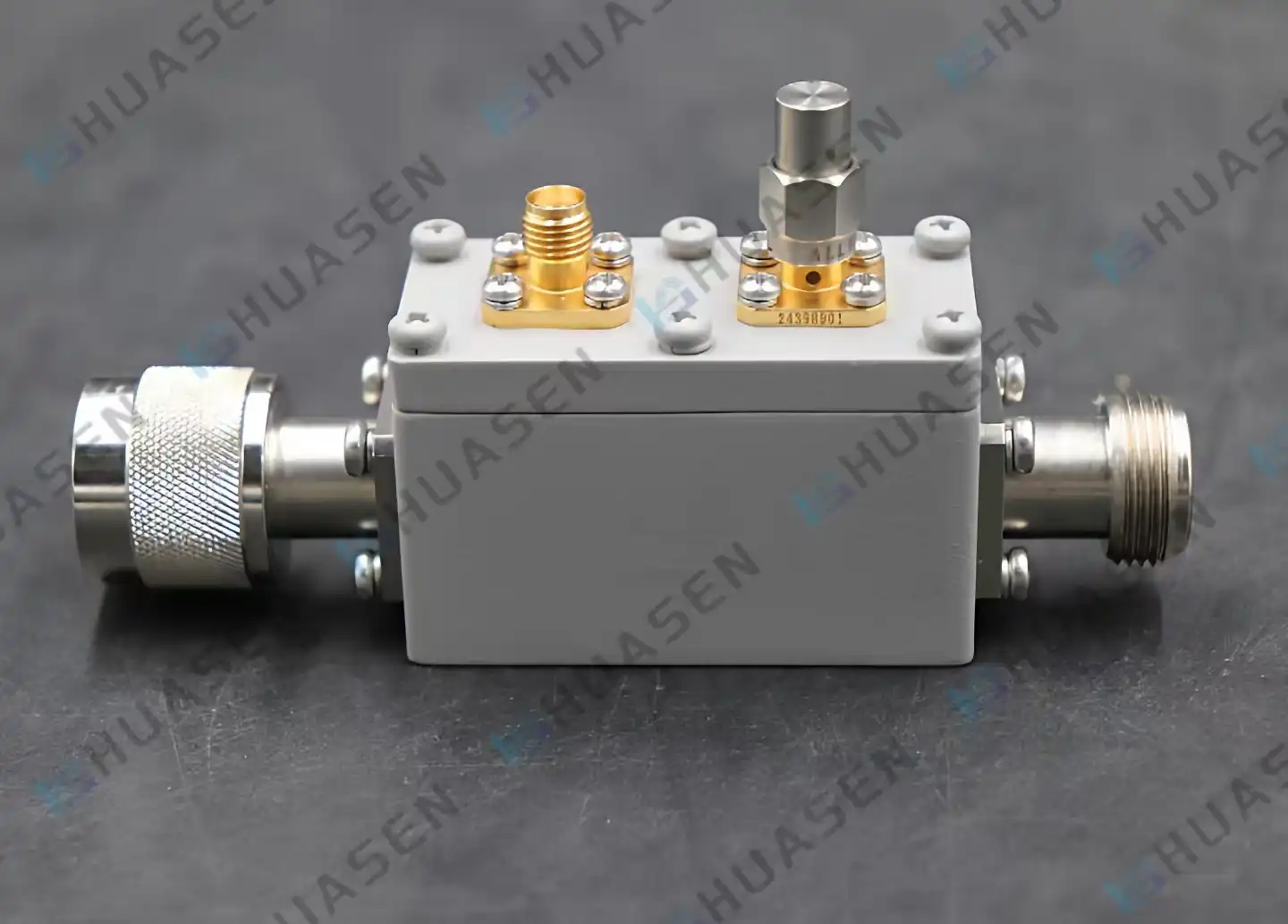
Why Coaxial Directional Couplers Are Ideal for RF Networks?
Superior Signal Integrity in High-Frequency Environments
Modern telecommunications need parts that keep the quality of the signal even at wide frequency ranges. Coaxial directional couplers keep the coupling flatness and low VSWR constant across their rated frequency range. This stops amplitude ripple that hurts the accuracy of modulation in 5G New Radio (NR) systems. The coaxial shape naturally blocks out outside interference, which is a big plus compared to open stripline setups in places where electromagnetic noise is a problem.
Advanced dielectric materials, like PTFE or air dielectrics, keep things stable at high and low temperatures, like those found in outdoor base stations or aircraft platforms. This stability means that the system will work the same way whether it's used for maritime communications in the Arctic or radar installations in the desert. This meets the needs of system integrators for adaptability in different environments.
Robust Power Handling for Demanding Applications
Base station amps and radar emitters make kilowatts of RF power, which means they need parts that can handle harsh circumstances. High-Power Coaxial Directional Couplers, like the CHPC series that can handle 500W of power, have housings that are thermally optimized and dielectrics that can handle high voltages. Arcing and thermal runaway are problems that can happen and put mission-critical defense or communication systems at risk. These designs stop them.
When testing high-power amplifiers, labs need couplers that can handle peak pulse conditions without breaking down. A correctly defined unit allows for constant tracking during burn-in testing, which speeds up the time it takes for equipment makers to get their products on the market and makes sure they meet MIL-STD-810 environmental standards.
Material Excellence and Design Innovation
Precision manufacturing sets professional-grade couplers apart from cheaper alternatives. CNC-machined housings have tight specs that keep the characteristic impedance level, which has a direct effect on directivity and return loss. In naval and coastal settings, where salt fog speeds up connection degradation, gold-plated connectors prevent rust. This makes them last longer, which lowers the total cost of ownership.
Fully sealed cases meet IP67 ratings for entry protection, keeping internal parts of outdoor spread antenna systems safe from dust and water. Passive intermodulation (PIM) is stopped by this encapsulation as well. PIM is when nonlinear junctions send out unwanted signals that mess up sensitive receivers. Low-PIM performance, which is usually defined as -160dBc or better, is very important for LTE and 5G infrastructure used by carriers.
| Parameter | Standard Type (CC) | High Power Type (CHPC) | Bidirectional Type (CDC) |
|---|---|---|---|
| Average Power Handling | 100W | 500W | 150W |
| Frequency Range | 0.5–18 GHz | 0.8–6 GHz | 0.03–40 GHz |
| Coupling Range | 10–50 dB | 10–30 dB | 10–40 dB |
| Directivity | ≥20 dB | ≥18 dB | ≥22 dB |
| Primary Application | Signal monitoring | High-power transmission | Bidirectional signal analysis |
Verified Performance Through Industry Standards
Compliance documentation gives buyers confidence. Manufacturers with a good reputation put out detailed datasheets that include recorded S-parameters, power derating curves, and results from outdoor tests. By comparing specs to application needs, like making sure the directivity is correct at the highest frequency, you can avoid expensive field failures.
Third-party approvals, such as ISO 9001 for factory quality and RoHS compliance for materials, show that the supply chain is mature. System integrators who make complete solutions like tracking and group consistency because it lets them qualify once and use the solution in production without having to do it again.
Comparing Coaxial Directional Couplers With Other Coupler Types
Functional and Operational Trade-Offs
Waveguide couplers are more common than coaxial connections above 26GHz because coaxial connectors have more losses and trouble with mode transfer. Tens of kilowatts of power can flow through their thin metal structure, but they need big mounting clamps and pressure windows, which isn't good for electronics that don't have a lot of space. With coaxial options, the system is many orders of magnitude smaller, but it still works well for many Ka-band tasks.
Stripline couplers make it easy to put together microwave integrated circuits (MICs). While their flat shape lets power escape, it also lets outside shocks hit the tracks. When the system architecture allows discrete components, coaxial couplers work better in places where there is a lot of shaking and shaking, like in unmanned aerial vehicles or on ships' radar.
It takes lossy networks instead of paired lines to reach bandwidths that last tens of years. There is a 1–2 dB rise in insertion loss and a fall in directivity with this bandwidth. This makes measurements less accurate in vector network analyser applications. Engineers use coaxial coupled-line systems when they need to get accurate readings of return loss, and the directivity is more than 20dB.
Matching Coupler Type to Application Requirements
Before you pick link numbers, you need to know what measures will be needed later on. When you check the output of an emitter without putting too much stress on the safety circuits, a 10dB coupler can be used. It redirects 10% of the forward power. If you want to take power away from passive parts and feed it to active ones, you can use a tighter connection (6 dB or 3 dB).
The type and size of the connection are based on the frequency band. When they work below 6GHz, couplers can handle N-Type connections and less strict mechanical limits. This makes it easier to install in the field. Above 26 GHz millimeter-wave units use precise 2.92 mm or K-connections, torque tools, and alignment clamps to keep the connectors from breaking, which would make the electricity work less well.
Bidirectional couplers (CDC series) are needed in antenna tuning systems to track VSWR in real time. These couplers measure both forward and reflected signals at the same time. Because it can do two things at once, it gets rid of the need for parts that are already being used. This frees up rack space and makes it easier to connect things in production lines and RF test benches.
| Coupler Type | Frequency Range | Power Handling | Typical Directivity | Installation Complexity | Cost Factor |
|---|---|---|---|---|---|
| Coaxial | 0.03–40 GHz | 100W–500W CW | 20–30 dB | Low (standard connectors) | Moderate |
| Waveguide | 18–110 GHz | 10–100 kW CW | 25–40 dB | High (flange alignment) | High |
| Stripline | 0.5–26 GHz | 1–50W CW | 15–25 dB | Very Low (PCB mount) | Low |
| Resistive | 0.01–50 GHz | 10–100W CW | 10–20 dB | Low | Moderate |
Procurement Considerations for B2B Clients
Evaluating Suppliers and Manufacturing Capabilities
Established Coaxial Directional Coupler manufacturers maintain extensive parametric databases, enabling rapid quoting for custom frequency splits or connector combinations. Suppliers like Huasen Microwave, with three decades of RF component experience, offer engineering support to optimize coupling values for specific system architectures—a service particularly valuable when transitioning laboratory prototypes to production.
Custom production meets the specific needs of each project, such as using non-standard frequency bands for radar signals that aren't available on the market, military-spec plugs for defence contracts, or higher temperature values for downhole data. Check the vendor's certifications that confirm process control and supply chain audits. This will cut down on the time needed to qualify for AS9100-based aerospace programs.
Pricing Structures and Lead Time Optimization
The price of a component shows how complicated it is beyond the raw materials. Tightly coupled designs (3 dB) need more precise production than loosely coupled units (40 dB), which changes the cost per unit. When procurement managers negotiate framework agreements for recurring base station deployments instead of individual orders, economies of scale can be unlocked.
Lead times change for each type of goods. Items from the catalogue usually ship within a few weeks, but custom designs take an extra 6–8 weeks because they need to be tested on a prototype. When makers share project timelines early on, they can give technical resources and long-lead materials like specialised links. This keeps schedule slips from happening during system integration.
Datasheet Verification and Technical Documentation
A careful look at the datasheet makes sure that the specifications match the needs of the application. Check that the connection is flat across the whole frequency range. Power readings become inaccurate when there is too much fluctuation. If you are launching outside, check the placement loss at different temperature levels. Look at the mechanical drawings to find mounting hole patterns that work with racks or enclosures that are already in use.
Ask for test results for important factors like measured S-parameters across temperature, power derating curves that show the safest CW levels, and PIM test reports for telecom uses. Suppliers with a good reputation give out calibration papers that can be traced back to national standards. This meets the needs of quality checks and contracts.
Best Practices for Using Coaxial Directional Couplers in RF Networks
Installation Techniques for Optimal Performance
Using the right amount of torque keeps connectors from breaking and keeps the electricity flowing. Return loss is worsened when center conductors are crushed or dielectric beads are cracked by over-tightening. When you under-tighten, you leave tiny holes that can cause PIM or let water in. Use torque wrenches that are measured and set to the manufacturer's recommended values. For SMA connectors, this is usually 12 inch-pounds, and for N-type connectors, it's 18 inch-pounds.
Cable routing reduces stress on the machine. Instead of relying on the connector threads, support the coupler's weight on its own. This keeps fatigue failures from happening in places with a lot of vibration. Keep the bend radius of connected wires as small as possible to keep the phase stable. This is very important when measuring the phase distributions of antenna arrays.
Calibration and Troubleshooting Protocols
Regular calibration makes up for differences in how often connectors work and how old the cable is. Set up baseline measurements with traceable power meters and compare them to regular checks. Deviations of more than 0.5 dB should lead to an investigation. Between connections, clean the connectors with rubbing alcohol and lint-free swabs to get rid of any dirt or dust that could cause insertion loss.
Systematic isolation is the first step in troubleshooting. To be sure of failure, swap suspect couplers with known-good ones. A vector network analyser can be used to check all four ports for damage. Degradation in directivity is often a sign of contamination on the isolated port. Cleaning and removal can fix the problem without replacing the part.
Environmental Protection and Storage Recommendations
When not in use, store couplers with dust caps on them to keep particles from building up on the connecting sides. Keep the humidity in storage areas below 60% RH to keep connector shells from rusting. Temperature switching between storage and release settings needs to happen slowly because sudden changes cause condensation to form inside sealed housings, which damages the dielectric qualities.
These practices extend thecoaxial directional coupler component's lifespan in harsh industrial conditions. Proper handling, combined with environmental awareness, protects your investment while maintaining measurement integrity across years of field operation. System integrators implementing these protocols reduce unplanned maintenance and improve uptime for revenue-generating infrastructure.
Conclusion
Selecting a coaxial directional coupler optimizes RF network performance through precise signal sampling, robust power handling, and environmental resilience. The technology's inherent advantages—low insertion loss, high directivity, and connector standardization—address critical needs across telecommunications, aerospace, and defense sectors. Understanding key parameters like coupling factor and directivity, comparing architectural trade-offs against waveguide and stripline alternatives, and following installation best practices ensure maximum return on investment. Engaging with experienced manufacturers who offer custom design capabilities and comprehensive technical support streamlines procurement, reduces qualification time, and delivers reliable components meeting stringent industry standards.
FAQ
1. What frequency ranges do coaxial directional couplers cover?
Modern designs operate from 30 MHz to 40 GHz. Standard units typically serve sub-6GHz bands common in cellular and Wi-Fi applications, while specialized designs address millimeter-wave radar frequencies. Frequency selection depends on your system's operating band—verify coupling flatness across your full spectrum to maintain measurement accuracy.
2. How do I choose between 10dB and 30dB coupling?
Tighter coupling (10dB) extracts more power for measurement but loads the main signal path more heavily. Loose coupling (30 dB) minimizes main path disruption, ideal for monitoring without affecting transmission. Match coupling to your test equipment sensitivity and acceptable signal loss—spectrum analyzers with low noise floors tolerate looser coupling.
3. Can couplers be customized for specific applications?
Absolutely. Manufacturers accommodate custom frequency splits, non-standard connectors (SMA-K, N-K, 2.92mm), power ratings, and mechanical mounting configurations. Provide detailed specifications, including frequency range, coupling tolerance, power levels, and environmental conditions. Prototype validation typically adds 6–8 weeks but ensures an exact fit for proprietary system architectures.
Procurement and Technical Support Solutions
Huasen Microwave brings over 30 years of RF component manufacturing expertise to your signal monitoring challenges. Our Coaxial Directional Coupler portfolio spans 0.03GHz to 40GHz with coupling options from 10dB to 50dB, supporting both standard (CC) and high-power (CHPC) requirements. As a trusted Coaxial Directional Coupler manufacturer, we offer fully sealed designs meeting IP67 standards and custom configurations tailored to your frequency, power, and connector specifications. Whether you're deploying 5G infrastructure, aerospace telemetry, or laboratory test systems, our engineering team provides datasheet verification, sample evaluation, and responsive post-delivery support. Contact sales@huasenmicrowave.com to discuss your project requirements and receive detailed quotations aligned with your delivery schedules.
References
1. Pozar, David M. Microwave Engineering, 4th Edition. Wiley, 2011.
2. Bahl, Inder J. Lumped Elements for RF and Microwave Circuits. Artech House, 2003.
3. IEEE Standard 291-1991. IEEE Standard Methods for Measuring Electromagnetic Field Strength of Sinusoidal Continuous Waves.
4. Rizzi, Peter A. Microwave Engineering: Passive Circuits. Prentice Hall, 1988.
5. Collin, Robert E. Foundations for Microwave Engineering, 2nd Edition. Wiley-IEEE Press, 2001.
6. Carr, Joseph J. Microwave and Wireless Communications Technology. Newnes, 1997.
Send Inquiry