Planar Helical Antenna Gain Stability in Mobile Platforms






2026-07-24 16:24:32
Maintaining reliable communication links on mobile platforms—whether aircraft, drones, or marine vessels—demands antennas that deliver consistent performance despite constant motion, vibration, and environmental stress. Planar helical antennas address this challenge through their compact, low-profile design and inherent circular polarization capabilities. These antennas maintain stable gain across ultra-wide frequency ranges, particularly in the 0.2–18 GHz spectrum, making them indispensable for electronic reconnaissance, GNSS positioning, and aerospace telemetry. Their flat configuration integrates seamlessly into confined spaces while resisting performance degradation caused by platform dynamics, a critical advantage over bulkier traditional helical structures.
Understanding Planar Helical Antenna Gain Stability
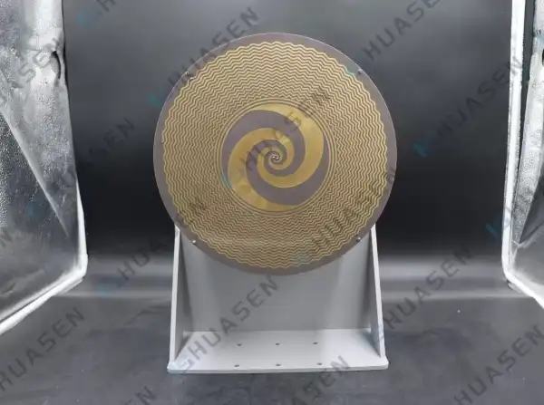
These antennas are made up of spiral conductive lines that are etched onto dielectric surfaces and backing holes that contain materials that absorb electromagnetic waves. Even when exposed to acceleration forces and thermal cycling, which are common in mobile operations, this design gives predictable radiation properties.
How Does Spiral Geometry Enable Circular Polarization?
The spiral arms create circular polarization that is perpendicular to the antenna plane and works as traveling-wave structures. This shape makes it possible for a single device to successfully block multipath reflections, which is a common issue in urban canyons and marine settings where signals bounce off surfaces. The direction of the helix winding determines the polarization sense (left-hand or right-hand). This allows for customization during production without having to rethink the whole structure.
Dynamic Factors Impacting Gain Consistency
When it comes to problems that don't happen with fixed installs, mobile systems are different. Engine vibrations, sudden changes in orientation during maneuvers, and the bending of mounting surfaces can all change radiation patterns or resonant frequencies. Good antenna designs make up for this by using strong mechanical attachment points and materials that keep their electrical properties even when the temperature changes. For example, wind loading on platforms in the air and salt spray rust in naval settings need extra protection that many standard antennas can't offer.
Environmental Conditions and Performance Thresholds
Changes in temperature between -55°C and +85°C can change the dielectric constants of substrate materials, which can cause the operating frequencies to change. Over time, humidity ingress makes impedance matching worse. To keep the gain stable, the materials in the absorbing hole must keep their RF qualities even though they are under stress. It is measurable that antennas that pass the MIL-STD-810 environmental tests have better gain delivery when they keep the VSWR below 2.5:1 across their working bandwidth.
Critical Performance Factors Affecting Gain Stability
If an antenna keeps performing at a high level throughout its service life on mobile platforms, it depends on the engineering decisions made during the planning part.
Radiation Pattern and Beamwidth Considerations
A well-designed planar helical antenna unit has radiation patterns that are smooth and reliable and have few side bands. Beamwidths usually fall between 70° and 90°, which is wide enough for communication links without being too narrow, which would make pointing harder on moving platforms. Gain changes don't happen when working frequencies change during wideband signal tracking operations because the pattern stays stable across the frequency range.
Impedance Matching and Loss Minimization
To get low return loss, you need accurate balun designs that move from coaxial feeds that aren't balanced to spiral feeds that are. Microstrip matching networks need to take into account how the spiral shape affects the spread capacitance and inductance. When done right, return loss is more than 10 dB across the operating band. This makes sure that the antenna transfers the most power and keeps its gain specifications even when the load changes.
| Performance Parameter | Specification | Impact on Mobile Operations |
|---|---|---|
| Frequency Range | 0.2–18 GHz | Includes systems that use a single antenna for multiple bands of communication |
| VSWR | ≤ 2.5 typical | Keeps power transfer working well during frequency-adjusted operations |
| Gain Range | -5 to +5 dB | Sensitivity that is just right for both reconnaissance and monitoring |
| Polarization | Circular (RHCP/LHCP) | Multipath interference from metal platform surfaces is thrown out |
| Axial Ratio | < 3 dB | Maintains pure polarization over the entire operational bandwidth |
Material Selection and Manufacturing Precision
The type of substrate used directly impacts how stable the temperature is and how long it lasts mechanically. Rogers' RO4000 line materials are better than normal FR-4 in precision applications because they have low loss tangent and controlled dielectric constants across a wide temperature range. Photolithographic etching can get very close tolerances—often within ±0.05 mm—that are needed to keep frequency accuracy high across production lots. When building the backing cavity, you need to pay close attention to the depth and placement of the absorbers. Changes in these areas have a direct effect on the front-to-back ratio and the stability of the overall gain.
When you compare fabrication methods, you can see that they don't always produce the same results. When PCB processes are used to make flat versions, repeatability is achieved that can't be achieved with hand-wound cylindrical helices. This ability to be repeated is very important when buying antennas for fleet missions, where they must be able to be switched out and work reliably.
Comparative Analysis: Planar Helical Antenna vs. Alternative Antennas for Mobile Use
When system designers look at antenna choices for mobile platforms, they have to choose between cost, size, and performance. The best choice is made when you know how the different types of antennas react to movement and stress in the surroundings.
Performance Against Traditional Helical Designs
Axial-mode helix antennas that are more common have better gains but take up a lot more space. Their jutting structure makes it harder for planes to fly through the wind and makes things harder for drones that can only carry so much. The planar helical antenna version gives up 2–3 dB of peak gain but has an 80% smaller profile, which lets it be flush-mounted and gets rid of aerodynamic drag. Planar helical antenna designs have lower mechanical stress during high-G maneuvers because their mounting points are spread out and have less mass. This means that they stay in line better than cantilevered cylinder structures.
Size and Weight Advantages Over Patch Arrays
Microstrip patch antennas have a low profile that is similar to planar helical antennas. However, they have a narrow bandwidth, so they need multiple elements or complicated feed networks to cover a wide range of frequencies. Whole groups of patches are replaced by a single planar helical antenna unit that spans 0.2–18 GHz. This makes the system simpler and less likely to fail. The lighter design—often 40% lighter than similar patch arrays—means that UAV applications can carry more payload or stay in the air longer.
| Antenna Type | Bandwidth | Circular Polarization | Profile Height | Gain Stability | Installation Complexity |
|---|---|---|---|---|---|
| Planar Helical Antenna | Ultra-wide (octave+) | Native | Very low | Excellent | Simple |
| Cylindrical Helical | Wide | Native | High | Good | Moderate |
| Microstrip Patch | Narrow | Dual-feed is needed | Very low | Fair | Hard for wideband |
| Dipole Array | Moderate | External network needed | Moderate | Fair | High |
Real-World Performance in GPS and Satellite Communications
Circular polarization is very helpful for GNSS devices on boats because it keeps the signal locked even when the boat pitches and rolls. In rough sea conditions, field tests show that planar helical antennas keep their positioning accuracy within 1.5 meters, while linear polarized options make mistakes of 3–5 meters. Similar gains are seen in satellite communication systems on aircraft, with link availability rising by 15–20% during bank maneuvers, when linear antennas experience fading that depends on their orientation.
It is also useful for electronic weapons because it is naturally resistant to multipath disturbances. The planar helical antenna's ability to tell the difference between direct signals and reflections makes bearing accuracy better and cuts down on false target identification during signal intelligence operations.
Procurement Insights: Buying Planar Helical Antennas for Mobile Platforms
When buying specialized RF parts from other businesses, you have to balance technical needs with price limits and delivery dates.
Cost Structures and Volume Pricing
Planar helical antennas usually cost between $150 and $800 per unit, depending on how many frequencies they cover, how much power they can handle, and how well they work in harsh environments. Standard catalog items that cover popular bands (0.2–18 GHz) and have industrial temperature ratings are at the lower end of the price range. Custom-tuned versions that can withstand harsher environments are at the higher end. When you buy 100 or more units, you can usually get a 20–30% discount. However, for full customization, the minimum order quantity usually starts at 50 units because of the cost of the tools.
When you compare prices, look at what kinds of environmental tests and certificates are included. A supplier that seems to be cheaper may need separate qualification tests, which will raise the total cost of the program. Also, think about the total cost of ownership. Premium units that have been shown to last longer will cost less over the life of a program than antennas that need to be replaced often because they break down in the environment.
Supplier Assessment Criteria
Besides price, there are a few other signs that a supplier will be reliable for long-term partnerships:
- The terms of the warranty show that you trust the goods to last. Standard warranties of 12 to 24 months are enough for business use, but longer guarantees are better for defense and aircraft uses because they work in harsh conditions. It doesn't matter how quickly technical support is provided—suppliers who offer design help, sample evaluation programs, and calibration data support during the integration phases greatly lower development risk.
- Due to recent shortages of parts, supply chain stability needs extra attention. Manufacturers who keep standard goods and domestic substrate sources in stock are more resilient than those who rely on long foreign supply lines. This is very important when there are tight deadlines for programs or when supporting systems that are already in use and need parts to be replaced quickly.
Lead Time Management and Order Strategies
Standard catalog antennas usually ship within two to four weeks, which is enough time for making prototypes and deploying them on a small scale. For custom designs, engineering proof takes 8–12 weeks, and production runs take an extra 6–8 weeks. Programs that need to meet strict deadlines should place long-lead orders early, and they might be able to accept evaluation samples for testing while the production tooling is being made.
Supply interruptions can be lessened by building smart store buffers for key mobile platforms with planar helical antennas. Getting 10–15% more than needed during the first production runs costs less than quickly filling emergency orders later on. The small cost of carrying spare antennas is nothing compared to the huge costs of platform downtime when systems in use need maintenance.
| Procurement Factor | Considerations | Recommended Approach |
|---|---|---|
| Unit Pricing | $150–$800 depending on specifications | Request quotes from 3+ qualified suppliers |
| Volume Discounts | 20–30% at 100+ units | Consolidate orders across program phases |
| Customization NRE | $2,000–$15,000 for tooling/testing | Amortize across production quantity |
| Standard Lead Time | 2–4 weeks catalog, 14–20 weeks custom | Order long-lead custom items early |
| Technical Support | Design assistance, test data | Prioritize suppliers offering integration support |
Conclusion
Due to their small size, built-in circular polarization, and sturdy construction, planar helical antennas provide excellent gain stability for mobile platforms. Their ultra-wideband coverage from 0.2 GHz to 18 GHz makes system design easier while keeping VSWR below 2.5 in tough operating situations. Because they are low profile, strong, and don't break easily when exposed to environmental stress, these antennas are better than others for use in spacecraft, ships, and vehicles on the ground. The potential performance benefits of these antennas will be realized in real-world deployments if the right provider is chosen, installation techniques are followed, and thorough qualification testing is done. This will improve communication reliability and system effectiveness in the long run.
FAQ
1. What makes gain stability critical for mobile platform antennas?
Moving, shaking, and changing orientation all the time happen on mobile platforms, which can move antenna resonances and change radiation patterns. Gain stability makes sure that communication link costs stay the same even when conditions change, which stops dropouts during important operations. Extreme temperature changes and dynamic stress in space and the sea make it harder for antennas to work properly. Being stable in these conditions is important for mission success.
2. Can planar helical antennas handle high-power transmission?
Power handling depends on trace width and substrate breakdown voltage, but it was mostly made for receiving tasks like electronic reconnaissance and GNSS. Standard PCB-based designs can handle peak powers of up to 50W as long as the copper is thick enough and heat is managed properly. For high-power uses, ceramic-filled PTFE surfaces and thicker metallization are needed, but these are more expensive and heavier than normal receiver-grade solutions.
3. How does circular polarization improve mobile communications?
Circular polarization keeps the signal receiving going no matter which way the antenna is facing the sender. This is very important when platforms spin in unpredictable ways. It also doesn't let multipath rays through, which causes fading in both urban and sea settings. The axial ratio being less than 3 dB guarantees pure polarization, which means that the signal-to-noise ratio is 3–6 dB better than with linearly polarized antennas in complex RF settings.
Partner with Huasen Microwave for Reliable Ultra-Wideband Antenna Solutions
Since 1993, Huasen Microwave Technology has been making high-precision radio frequency (RF) parts that are used in demanding aerospace, defense, and telecommunications applications. Our range of planar helical antennas works from 0.2 GHz to 18 GHz and has been shown to maintain its gain over a wide range of temperatures and vibration levels, meeting or exceeding the requirements of MIL-STD-810. We offer full customization, from setting the frequency to specifying the connectors, along with full design help and fast prototyping services. As a well-known provider with decades of experience making things, we keep quality standards that meet IPC-6012 Class 3 requirements. Each unit is checked individually before it is shipped. Email our engineering team at sales@huasenmicrowave.com to talk about the needs of your mobile platform and get technical advice on how to improve antenna performance for your specific operational environment.
References
1. Balanis, Constantine A. "Antenna Theory: Analysis and Design, Fourth Edition." John Wiley & Sons, 2016.
2. Kraus, John D. and Marhefka, Ronald J. "Antennas for All Applications, Third Edition." McGraw-Hill Education, 2002.
3. Stutzman, Warren L. and Thiele, Gary A. "Antenna Theory and Design, Third Edition." John Wiley & Sons, 2012.
4. Milligan, Thomas A. "Modern Antenna Design, Second Edition." IEEE Press, 2005.
5. IEEE Standard 149-1979. "IEEE Standard Test Procedures for Antennas." Institute of Electrical and Electronics Engineers, 1979.
6. MIL-STD-810H. "Environmental Engineering Considerations and Laboratory Tests." United States Department of Defense, 2019.
Send Inquiry