Comparing Ridge, Tapered and Waveguide Transition Structures






2026-07-27 10:02:25
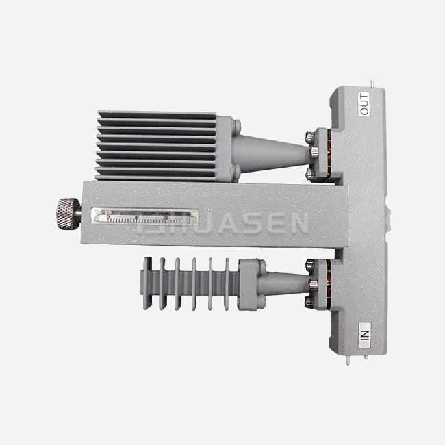
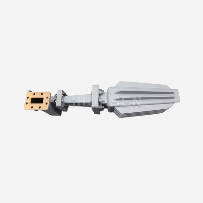
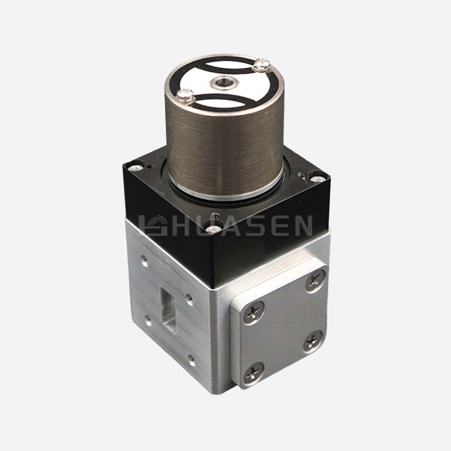
When selecting high-frequency RF components for critical telecommunications or radar applications, the choice between ridge, tapered, and standard waveguide transition structures can significantly impact system performance and long-term operational costs. A waveguide transition serves as an impedance-matching bridge that couples RF energy between dissimilar transmission line geometries—such as connecting a WR-112 rectangular waveguide to a WR-90 section or interfacing coaxial feeds with waveguide antenna systems. These passive components minimize signal reflection and preserve mode purity, directly influencing parameters like VSWR, insertion loss, and power handling capacity. Understanding the structural and electrical differences among ridge, tapered, and conventional transition designs enables procurement professionals to match component specifications with application demands, whether optimizing satellite uplink chains, integrating compact airborne radar modules, or establishing precision calibration setups in RF testing laboratories.
Understanding the Basics of Waveguide Transition Structures
Waveguide transitions work like impedance transformers, lining up the characteristic impedance between the source and the load so that signals can travel efficiently through different waveguide cross-sections or transmission media. At microwave and millimeter-wave frequencies, abrupt changes in shape cause reflections that lower the efficiency of the system and can hurt high-power amplifiers. When transitions are properly designed, they use tapered profiles or stepped internal structures, which are often based on Chebyshev or binomial matching principles, to change impedance gradually and keep VSWR low across the operational bandwidth.
Core Operating Principles and Key Parameters
There are three basic electrical factors that determine how well a transition design works: insertion loss, return loss, and bandwidth. Insertion loss measures how much the signal is weakened as it passes through the component. It usually falls between 0.1 dB and 0.3 dB, depending on the length and quality of the surface finish. VSWR, or return loss, shows how much power is reflected back toward the source. For industrial-grade units, VSWR numbers below 1.25:1 are normal, while for metrology-grade transitions, they should be below 1.10:1. The frequency range that these performance metrics stay within is determined by the bandwidth, which is very different for tapered and stepped designs.
Common Transition Types and Industrial Applications
Modern waveguide transition design is based on three main architecture methods. Ridge-loaded transitions use vanes or ridges inside to lower the cutoff frequency. This lets them cover a wider range of frequencies in a smaller space. To get very low reflection over a wide frequency range, tapered transitions use slow changes in dimensions, such as linear, exponential, or optimized curves. They need longer physical lengths, though. Standard stepped transitions use quarter-wave transformer sections set up in multi-stage networks. This makes the transitions smaller, but the bandwidth is less. These designs are very useful in satellite ground stations where high-power amplifiers connect to antenna feed assemblies, in aircraft fire-control radars that have to work in tight spaces, and in vector network analyzer calibration setups that need to be very accurate with their measurements.
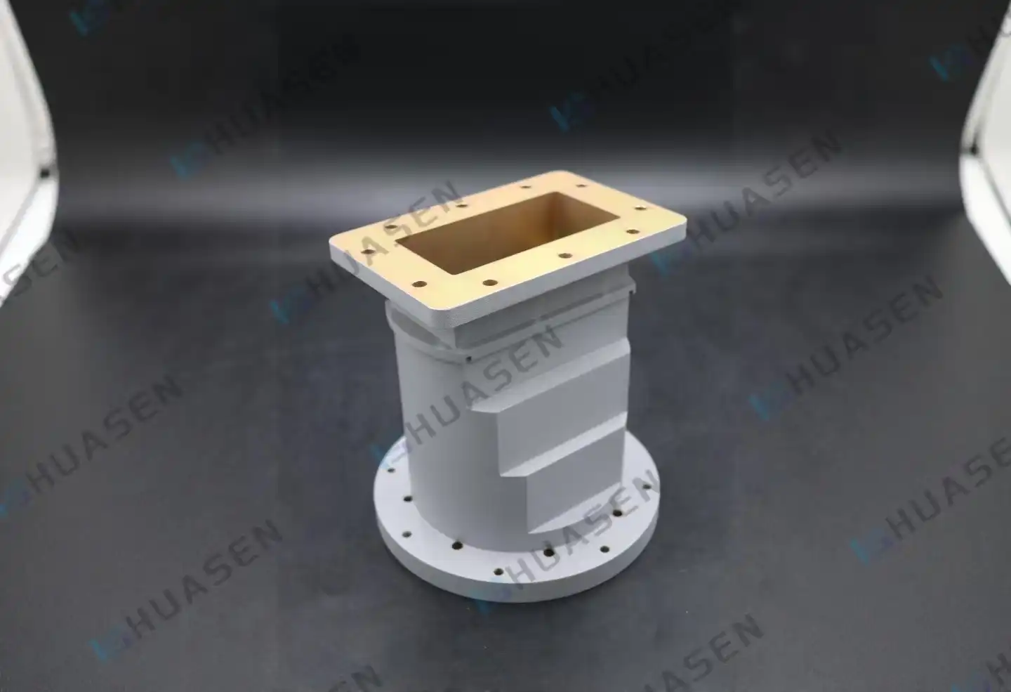
Comparative Analysis of Ridge, Tapered, and Standard Waveguide Transition Designs
To choose the best transition architecture, you need to know how each design method balances mechanical limits with electrical performance. The next part of the study compares the three main groups' structural features, RF measures, and environmental resistance.
Structural Design Characteristics and Geometry
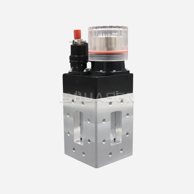
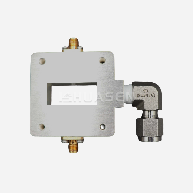
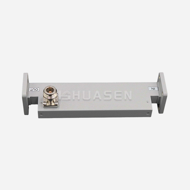
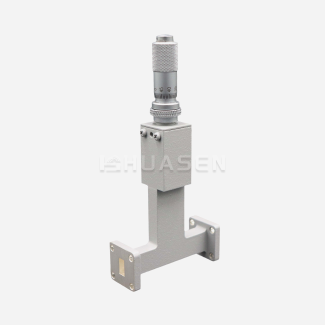
Ridge transitions change the internal waveguide cross-section by adding metallic ridges or vanes along the wide walls. This lowers the cutoff frequency and lets the part work over multi-octave bandwidths while taking up less space. This shape is useful for installations with limited space, such as communication systems on drones or small front ends for base stations. Profile optimization methods figure out the rate of taper to keep reflections to a minimum. Tapered transitions keep the changes in size between the input and output flanges smooth and continuous. These units usually have a length of several bands, which means they can be used for placements on the ground if there is enough room. In order to achieve impedance matching through multi-section networks, standard waveguide-to-waveguide transitions depend on sharp step changes determined as quarter-wavelength transformers at discrete frequencies. Even though this stepped approach is small, it naturally has less operational bandwidth than tapered alternatives.
Performance Metrics: Insertion Loss and Efficiency
When you look at insertion loss across frequency bands, you can really tell the difference in performance. The following table shows typical specs for X-band transitions (8.2-12.4 GHz) that can handle moderate power levels:
| Transition Type | Typical Length | Insertion Loss | VSWR | Bandwidth | Power Handling |
|---|---|---|---|---|---|
| Ridge-Loaded | 40-60 mm | 0.15-0.25 dB | 1.20:1 | >40% | 5-20 kW peak |
| Linear Tapered | 80-120 mm | 0.08-0.15 dB | 1.15:1 | >50% | 10-50 kW peak |
| Stepped (3-section) | 30-45 mm | 0.25-0.35 dB | 1.25:1 | 20-30% | 5-15 kW peak |
Ridge designs combine moderate insertion loss with small size, which is why they are best for mobile and airborne platforms where weight and volume are important factors in buying choices. Tapered configurations offer better electrical performance with low loss and excellent VSWR. This is why they are used in high-power radar transmitters and satellite earth stations where signal integrity is more important than size. Stepped transitions take up the least amount of space and work well in situations where space is tight, but bandwidth is still plenty, like point-to-point microwave links that use limited frequency ranges.
Thermal Behavior and Mechanical Robustness
Extreme temperature changes, vibrations, and corrosive atmospheres can have a direct effect on the long-term dependability of defense and communications systems that are used outside. A greater choice of material is very important. For aircraft use, aluminum alloy (6061-T6) is a great way to reduce weight, and it is usually coated with chromate or plated with silver to stop rusting. Oxygen-free hard copper (OFHC) is the best electrical conductor and is often used in research settings and fixed ground installations where temperature stability is more important than mass. Waveguide transition ridge transitions have a more complicated internal shape, which could lead to stress concentration points when the temperature changes from -55°C to +85°C. Designs that are tapered and have smooth curves spread heat expansion evenly, which lowers mechanical stress. Stepped transitions can lead to performance loss at the joints between sections if differential thermal expansion lowers the contact pressure. This is especially likely in units that were badly made and didn't use the right brazing or electroforming methods. Environmental stress screening should be required in the procurement requirements. For marine radar sites, this should include salt spray testing according to ASTM B117, and for military platforms, it should include shock and vibration qualification according to MIL-STD-810.
Selecting the Right Waveguide Transition for Your Microwave System
To make good buying choices, you need to weigh technical needs against budget facts and supply chain concerns. First, system-level requirements are set, and then each waveguide transition type is judged on how well it meets specific operational needs.
Evaluating Efficiency, Cost, and Delivery Considerations
Metrics for efficiency include more than just insertion loss numbers; they also take into account the whole system's effect. In a 20-stage repeater chain, a shift with 0.3 dB insertion loss adds up to 6 dB of total loss, which could mean adding an extra amplifier stage that costs thousands of dollars and lowers the noise figure. In large-scale deployments, this analysis often supports charging more for low-loss tapered designs. Off-the-shelf stepped transitions for popular bands (X, Ku, and Ka) cost $200 to $600 per unit and have wait times of two to four weeks. Custom tapered designs for specific frequency ranges may cost $1,500 to $4,000 and have fabrication processes of eight to twelve weeks. Ridge changes usually cost between $600 and $1,500, and they can be customized to a modest degree. People who work in procurement should ask sellers for specific loss budgets and compare the total system cost instead of just the unit price. When planning a project, delivery times are very important. Having relationships with several qualified suppliers lowers the risk of relying on just one, and it also gives you more power when bidding.
Waveguide Transitions versus Alternative Interconnect Solutions
Different technologies come with different trade-offs that should be thought about during the system planning stages. Coaxial-to-waveguide adapters let you connect test equipment or modular sections in a variety of ways, but because they use coaxial cables, they can only handle peak power levels in the kilowatt range, while all-waveguide lines can handle megawatts. Microstrip-to-Waveguide Transitions help integrate flat circuits in millimeter-wave applications, but they have more loss and a smaller bandwidth than a straight waveguide connection. Power needs, frequency coverage, physical limitations, and the need for standardization of the interface should all be taken into account in the decision matrix. For example, the front end of a 5G massive MIMO base station might use ridge transitions between the power amplifier array and the antenna feed network, putting small size and wide bandwidth at the top of the list to allow for dynamic spectrum allocation. On the other hand, a satellite ground terminal that works at set C-band frequencies would benefit from a precision-tapered transition that minimizes insertion loss and lets the high-power amplifier output stage handle as much power as possible.
Customized versus Standard Off-the-Shelf Solutions
Standard catalogue goods are available right away and have been shown to be reliable. They are also compatible with UG-style or CPR flanges and have a lot of field usage data to back them up. These units work well for making prototypes, doing small runs of production, and using them in ways that work with common frequency bands. When a system needs non-standard frequency ranges, special flange designs, built-in filtering functions, or high environmental grades, custom engineering is needed. The first step in customizing something is usually figuring out the electrical needs (like frequency range, VSWR limits, and power handling), the mechanical ones (like mounting interfaces, envelope dimensions, and mass targets), and the environmental ones (like operating temperature range, sealing requirements, and coating specifications). Reputable makers offer design help, such as electromagnetic simulation results, thermal analysis, and review of sample units before committing to large-scale production. This way of working together lowers the risk of buying a waveguide transitionand makes sure that supplied parts meet the needs for system integration without having to go through expensive redesign cycles.
Conclusion
When you look at the performance differences between ridge, tapered, and standard waveguide transition structures, they have a direct effect on how microwave and RF systems are built. Ridge-loaded designs offer high bandwidth in small sizes, making them ideal for mobile and airborne uses where room is limited. Tapered transitions offer better electrical performance with low insertion loss and high VSWR, which is why they are used in high-power ground installations and precise measurement systems. Stepped transitions have the smallest size and work well enough electrically for uses with limited bandwidth. To do good procurement, you need to look at the overall system impact instead of just the specifications of each part. You need to think about how transition losses build up along signal chains and affect the staging needs of amplifiers. Working with makers that offer full technical support, such as design help and thorough qualification data, lowers the risk of integration and makes sure that the supplied parts meet practical needs. As radio frequency (RF) systems continue to change toward higher frequencies and higher power densities, procurement teams can use new transition technologies to make future system upgrades more effective by staying up to date on new technologies.
FAQ
1. What frequency ranges suit each waveguide transition type?
Ridge transitions work well over a wide range of frequency ranges, usually between 6 and 18 GHz for C/X-band uses or between 18 and 40 GHz for Ka-band. This makes them perfect for broad radar and electronic warfare systems. Tapered designs work with all waveguide working ranges and have bandwidth ratios of more than 1.5:1. They can be used for everything from L-band satellite communications (1-2 GHz) to W-band test systems (75-110 GHz). Stepped transitions usually work with smaller chunks of 20–30% fractional bandwidth, which are good for fixed-frequency radar and point-to-point microwave lines.
2. How does the insertion loss difference impact system performance?
In systems with more than one stage, the difference in performance between ridge and tapered transitions gets bigger. If you multiply a 0.2 dB improvement in tapered design insertion loss by 15 transition points in a phased array feed network, you get a 3 dB total improvement. This is the same as doubling the transmitter's power or extending the communication range by 40%. This calculation shows that charging more for low-loss parts is reasonable in large-scale deployments where overall costs are more important.
3. Can custom waveguide transitions ship on expedited schedules?
Standard customizations, like different types of flanges or different lengths on existing designs, usually ship within 4 to 6 weeks from qualified suppliers who keep production going. Timelines are extended to 10–14 weeks for complex custom engineering that needs new electromagnetic models and tooling manufacturing. Sharing project plans during the initial quote stages lets providers book production slots and find ways to speed up the process by working extra hours or doing steps at the same time.
Partner with Huasen Microwave for Premium Waveguide Transition Solutions.
Huasen Microwave Technology offers precisely designed ridge, tapered, and standard waveguide transitions, backed by 30 years of experience making these kinds of parts. Our vertically integrated production facility oversees every step of the manufacturing process, from choosing the OFHC copper billet to performing the final VNA testing. This makes sure that electrical performance standards like <1.15:1 VSWR and <0.15 dB insertion loss are always met across all production batches. We help tough telecommunications, aerospace, and defense projects by customizing products across frequency ranges from L-band to W-band, handling power levels from lab-grade milliwatts to multi-kilowatt radar transmitters, and making sure they meet MIL-STD-810 requirements for shock, vibration, and thermal cycling.
Our engineering team works with procurement professionals and system builders to make sure that the transition specs are the best they can be for each application. They do this by analyzing electromagnetic simulations, modelling thermal conditions, and testing samples before committing to a personalized action. As a well-known waveguide transition manufacturer, we keep in touch with you quickly and clearly throughout the lifecycle of a project. We also provide waveguide transition documentation, such as S-parameter files, mechanical CAD models, and qualification test reports, that makes the integration process easier for you. Get in touch with our experts at sales@huasenmicrowave.com to talk about your project's needs, get personalized suggestions for parts, and get access to cheap pricing models that are made for both small prototypes and large production runs. Let us show you how precise waveguide transition options can improve the performance of your RF system while still meeting tight deadlines and spending limits.
References
1. Pozar, David M. Microwave Engineering, 4th Edition. Hoboken: John Wiley & Sons, 2012.
2. Balanis, Constantine A. Advanced Engineering Electromagnetics. New York: Wiley, 2012.
3. Collin, Robert E. Foundations for Microwave Engineering, 2nd Edition. New York: IEEE Press, 2001.
4. Saad, Theodore S. The Microwave Engineer's Handbook and Buyer's Guide. Norwood: Artech House, 2013.
5. Matthaei, George L., Leo Young, and E.M.T. Jones. Microwave Filters, Impedance-Matching Networks, and Coupling Structures. Norwood: Artech House, 1980.
6. IEEE Standard 1785-2016. IEEE Standard for Rectangular Metallic Waveguides and Their Interfaces for Frequencies of 110 GHz and Above. New York: Institute of Electrical and Electronics Engineers, 2016.
Send Inquiry