Coax Cable vs Fiber Optic Cable: Key Differences Explained






2026-07-17 16:00:52
People who work with radar, telecommunications, and RF tests need to choose between coaxial cable and fibre optic cable, which is a very important infrastructure choice. A copper wire and several layers of insulation make up a coax cable bundle. RF signals from DC to 60 GHz can be sent very well through them, which is why they are needed to connect base stations, test equipment, and radar systems. Light bursts are used by fibre optic lines to send data through layers of glass. They have the most bandwidth, which means they can send digital messages over long distances. The buying teams can pick the best system for their needs once they know the technical and real differences between these two.
Understanding Coax and Fibre Optic Cables: Basics and Applications
Internal Structure of Coaxial Cables
In coax cables, there is a copper conductor in the middle that is surrounded by dielectric insulation. On the outside, there is a protective jacket and a metal shield that is braided. This set-up in a circle keeps the resistance the same, which is usually 50 Ohm for RF use and 75 Ohm for video transmission. It also keeps data safe from interference from radio waves. It is possible for coax cable assemblies to handle high-frequency signals with little phase shift because of how they are built. This is especially true when low-loss dielectrics like PTFE or FEP are used. As high as 40 GHz, coax lines can keep VSWR levels below 1.5, which is why they are used in places where signals need to be sent properly, such as 5G base station front haul or vector network analyser test kits.
How Do Fibre Optic Cables Transmit Data?
Fibre optic lines are made up of bands of very clean glass or plastic. Lasers or LEDs use them to send light messages. There is a layer around the core thread that has a lower refractive index. The light stays inside the core because of the total internal reflection that occurs. This means that data can be sent over thousands of kilometres at speeds of more than 100 Gbps without having to use repeaters. Fibre is useful for telecommunications backup networks, underwater communication links, and data centre interconnects because it can bundle multiple bands into a single strand (called dense wavelength division multiplexing) and doesn't get messed up by radio frequency interference.
Primary Industrial Applications
Radio waves (RF) are used in places with a lot of them so that the quality of the signals at microwave and millimetre-wave frequencies can't be harmed. To connect radio heads that are far away to antennas, base station builders use special coax cable links with 2.92 mm or N-type connections. If these wires are going to be used outside, they need to be weatherproof and meet IP67 standards. MIL-DTL-17 standards say that aerospace radar systems need coax cables that are phase-stable, semi-rigid, and can handle vibration. People in the lab use low-insertion loss (≤ 6.5 dB at 40 GHz) flexible coax cable assemblies to calibrate spectrum analysers and signal generators.
Fibre optic lines are best when speed and distance are more important than how well they work with radio waves. Satellite ground stations use fibre links to send IF signals from antenna feeds that have been digitised to processing centres. For ships' transmission systems, armoured fibre lines that don't rust in salt water are used. When fibre backhaul signals are sent, point-to-multipoint wireless bridging systems change them into radio frequency (RF) for last-mile distribution. This tech takes the best parts of both and uses them together.
Comparative Analysis: Technical Features and Performance
Frequency Range and Bandwidth Capabilities
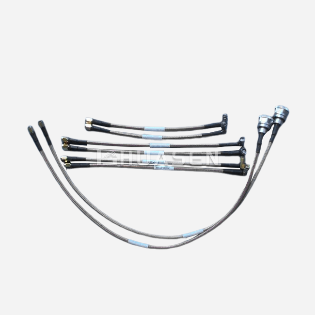
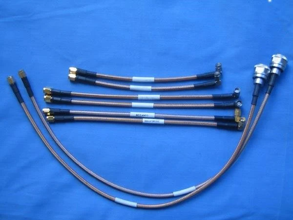
From DC to millimetre waves, coax lines can handle them all. Up to 18 GHz, standard coax cable kits with SMA ends work fine. The frequency can be raised to 40 GHz with precise 2.92 mm connections. When using a phased array antenna system, it is very important that the electrical length errors don't go over picoseconds. This is what phase-matched coax wire sets do. The performance specs for high-quality coax cable assemblies are shown in the table below:
| Parameter | Specification | Application Impact |
|---|---|---|
| Frequency Range | DC to 60 GHz | Supports 5G FR2, Ka-band satellite, millimeter-wave radar |
| Insertion Loss | ≤ 6.5 dB @ 40 GHz | Minimizes signal degradation in long runs |
| VSWR | ≤ 1.5 @ 40 GHz | Ensures efficient power transfer, reduces reflections |
| Connector Types | SMA, N, 2.92, 2.4, K, DIN 7-16, QMA | Enables compatibility with test equipment and antenna interfaces |
| Dielectric Material | PTFE, FEP | Provides thermal stability from -55°C to +200°C |
Compared to other types of lines, fibre optic cables have almost endless capacity. Single-mode fibres can carry data across the entire C-band and L-band optical range (1530-1625 nm). DWDM technology lets a single fibre strand multiplex more than 80 channels at 100 Gbps each. Coax cables can't even come close to this. For RF applications, however, fibre needs to be changed from optical to electrical, which makes radar and base station systems more complicated.
Signal Attenuation and Loss Characteristics
The attenuation of a coaxial wire goes up with frequency and cable length. It is common for an LMR-400 coax cable setup to lose about 6.7 dB per 100 feet at 2.4 GHz and 22 dB at 10 GHz. Attenuation is 30–40% less in low-loss stable-phase coax cable assemblies than in standard types. These include those with silver-plated copper wires and expanded PTFE dielectrics. Total insertion loss budgets need to be worked out by system designers. This is especially important in multi-stage RF chains where cumulative loss lowers the signal-to-noise ratio.
Fibre optic cables lose very little signal over long distances. For single-mode fibre at 1550 nm, the loss is usually only 0.2 to 0.5 dB per kilometre. There is less loss in a 10-kilometre fibre run than in a 10-metre run of 40 GHz high-frequency coax cable. Because of this, fibre is the only real option for long-distance phone calls and sensor networks that are far away. Connectorised fibre systems add 0.3 to 0.5 dB of loss per pair, but fusion splices lower that loss to less than 0.1 dB.
Environmental Durability and Robustness
UV-resistant jackets, armoured braiding, and hermetically sealed connectors are all parts of coax cable assemblies that are made for harsh environments. High-temperature torsion-resistant coax cable types can handle being bent, heated, and cooled many times without losing their performance. This is very important for aerospace applications where cables are subjected to G-forces and extreme temperatures. Waterproof systems with potting solutions inside get IP68 ratings, which means they can be submerged in water or used as outdoor base stations.
Fibre optic cables don't let any electromagnetic interference happen, so they can't be damaged by lightning hits, radio waves, or motor noise, which can happen with coax cable installs. For underground pipes, toughened fibre assemblies with Kevlar strength members and stainless steel armouring keep them safe from rodent damage and crushing forces. Ground loop problems can't happen in distributed antenna systems that span multiple buildings because there are no solid wires.
Practical Considerations for Installation and Usage
Connector Types and Termination Methods
Threaded RF connectors that are matched to certain frequency ranges and power levels are used in coax cable assemblies. SMA links are common in lab test leads and can handle frequencies up to 18 GHz. Base station wires mostly use N-type plugs, which are rated to 11 GHz and can handle 500 watts of power. For millimetre-wave uses, the 2.92 mm link increases bandwidth to 40 GHz and works with both K and SMA connections. To keep the resistance constant, the termination must be done precisely by pinching or soldering. Connectors that aren't connected properly cause VSWR spikes that reflect power and change signals.
Depending on the use and quantity, fibre optic lines can have LC, SC, or MTP/MPO connections. When they are terminated, single-mode fibres need to be perfectly lined up (within 1 micron). This is usually done with factory fusion splicing or field-installable mechanical splices. With pre-terminated fibre systems, you don't have to clean the fibres in the field, which cuts down on installation time and makes sure that the return loss stays below -50 dB. But fibre connectors can still get dirty; even a small piece of dust can scatter light and hurt link performance, so they need to be cleaned very carefully.
System Compatibility and Integration Challenges
When the resistance and connection types are the same, old RF systems that were built around coax cable infrastructure can work with newer coax cable units without any problems. When you replace test cables or upgrade base station antennas, you just swap them out without converting the signal. Phase-matched coax cable sets make it possible to retrofit array antennas in situations where more than one signal path needs to reach receivers at the same time.
To add fibre optics to RF systems, you need media converters or radio-over-fibre units that mix RF data with optical carriers. Fibre is used in distributed antenna systems to send signals from a central hub to antenna nodes that are far away. At these nodes, optical signals are changed back to radio frequency (RF) by transceivers that are nearby. In big systems, this mixed design cuts down on wire weight and loss, but each node costs more and uses more power.
Cost Analysis Across Procurement and Lifecycle
The comparison table below outlines total cost factors for B2B procurement teams evaluating bulk purchases:
| Cost Factor | Coax Cable | Fiber Optic Cable |
|---|---|---|
| Per-Meter Material Cost | Moderate (copper-based) | Low to High (depends on single/multimode) |
| Connector/Termination Cost | $15-$150 per end (precision RF) | $5-$50 per end (fusion splice) |
| Installation Complexity | Moderate (requires RF training) | High (requires fusion splicer, OTDR) |
| Testing Equipment | VNA, VSWR meter ($5,000-$50,000) | OTDR, power meter ($3,000-$30,000) |
| Maintenance | Connector cleaning, cable replacement | Cleaning, occasional re-termination |
| Scalability | Limited by attenuation at a distance | Excellent for long runs and high bandwidth |
Depending on the length, frequency, and space needed, a custom coax cable assembly with phase-matching and special connectors can cost anywhere from $200 to $2,000. The price per unit goes down when teams buy in bulk, but they need to make sure the seller meets quality standards like ISO 9001 and RoHS. They should also ask for VNA sweep test data to show that the electrical performance is good across the frequency range.
It costs less per kilometre to build fibre optic lines, but it costs more upfront to buy the tools and train the people who will put them in. Since fibre doesn't cost much to send over long distances, many lines can be set up. This lowers the total cost of ownership for long-haul lines. Fibre backhaul and coax cable delivery, on the other hand, are better for both cell phone networks and television centres because they use less money.
Decision-Making Framework: How to Choose Between Coax and Fibre Optic?
Evaluating Bandwidth and Distance Requirements
When systems need high-frequency RF communication with precise resistance control, procurement workers should put coax cables at the top of their list. Base station fronthaul links shorter than 100 metres, radar array feeds, and test instrument connections work best with low-loss coax cable arrangements that keep the phase stable. Systems that need bands above 30 GHz, like Ka-band satellite uplinks or millimetre-wave 5G nodes, need special coax cables with 2.92 mm or K connections to keep the signal from getting too weak.
When transmission distances go over a few hundred metres or when total data rates go over 10 Gbps, fibre optic cables are a must. Backhaul networks connect cell sites to core networks, underwater lines cross seas, and data centre interconnects all rely on fibre's huge speed and very little loss over distance. Fibre is good for projects that need to work in places where electromagnetic radiation is likely to happen, like power substations or industrial plants.
Assessing Environmental and Mechanical Constraints
Ruggedised designs are needed for applications that put cables in harsh conditions like weather, temperature changes, or physical stress. High-temperature torsion-resistant coax cable systems can handle being bent over and over again in aeroplane radomes or spinning antenna platforms. When buried or strung between utility poles, armoured fibre lines with crush-resistant jackets can handle it. System integrators have to make sure that the cable meets the needs of the operation. This includes checking the cable's IP grade, its ability to work in temperatures ranging from -55°C to +200°C, and its compliance with military standards (MIL-STD-810) for defence uses.
Supplier Reliability and Customisation Capabilities
When you buy coax cable from a reputable company, you can get it cut to length, in sets that are perfectly matched for antenna arrays, and with connectors that work with older devices. Assemblies from a good source come with a VNA test result that shows the insertion loss, VSWR, and phase departure as correct. Follow IPC/WHMA-A-620 Class 3 rules and get certifications like ISO 9001 to make sure that high-stakes deployments are always safe.
Fibre optic sellers should be good at fusion splicing and sell Coax cable units that are already ended and have measures for return loss and insertion loss that they can guarantee. For procurement teams, it's best to work with suppliers who have a lot of different types of fibres in stock, as well as those who can quickly fill special orders. Long-term relationships with suppliers that can offer technical support, such as help with on-site installation and calibration, lower the risks of a project and speed up the time it takes to deploy.
Conclusion
Selecting between coax cable and fibre optic cable hinges on application-specific requirements encompassing frequency range, transmission distance, environmental conditions, and system architecture. Coaxial cable assemblies remain the optimal choice for RF signal distribution at microwave and millimetre-wave frequencies, offering precise impedance control and compatibility with legacy infrastructure. Fibre optic cables excel in long-distance, high-bandwidth digital transmission where electromagnetic immunity is paramount. Hybrid solutions combining fibre backhaul with Coax cable distribution frequently deliver the best balance of performance and cost-effectiveness. Partnering with experienced suppliers who provide customisation, comprehensive testing, and responsive support ensures procurement decisions translate into operational success.
FAQ
1. What frequency ranges do coax cables support compared to fibre optics?
Coaxial cable assemblies operate from DC through millimetre-wave frequencies up to 110 GHz, depending on connector types and dielectric materials. Standard SMA connectors handle signals to 18 GHz, while precision 2.92mm connectors extend bandwidth to 40 GHz. Fibre optic cables do not transmit RF signals directly; instead, they carry modulated light in the 850 nm, 1310 nm, or 1550 nm wavelength bands. When used in radio-over-fibre systems, fibres can transport RF signals as modulated optical carriers, effectively becoming transparent to RF frequencies but requiring optical-to-electrical conversion at endpoints.
2. How does cable length affect signal loss?
Coaxial cable attenuation scales linearly with length and increases exponentially with frequency. A 10-metre run of LMR-400 Coax Cable loses approximately 0.67 dB at 2.4 GHz but 2.2 dB at 10 GHz. System designers must calculate total loss budgets carefully, often upgrading to larger-diameter cables (LMR-600) or low-loss, stable-phase assemblies for runs exceeding 30 metres at high frequencies. Fibre optic cables exhibit minimal loss—typically 0.2-0.5 dB per kilometre—making length almost negligible for single-mode fibres. A 10-kilometre fibre link introduces less loss than a 50-metre high-frequency coaxial cable run, explaining fibre's dominance in long-distance telecommunications.
3. Can coax cables be used outdoors or in harsh environments?
High-quality coax cable assemblies designed for outdoor deployment incorporate UV-resistant jackets (typically polyethylene or PVC compounds), corrosion-resistant connectors (nickel or stainless steel plating), and internal moisture barriers. IP67-rated assemblies withstand temporary immersion, while IP68-rated versions survive continuous submersion. Temperature ratings span -55°C to +200°C depending on dielectric materials (PTFE for high-temperature applications). Base station operators routinely deploy weather-sealed Coaxial cable jumpers connecting antennas to remote radio heads, with properly installed assemblies maintaining performance for 10+ years in coastal or industrial environments when connectors receive periodic inspection and cleaning.
Partner with Huasen Microwave for Your RF Connectivity Solutions
Huasen Microwave Technology Co., Ltd. brings over three decades of RF engineering excellence to your mission-critical projects. As a specialized Coax Cable assemblies manufacturer, we deliver custom-engineered solutions spanning DC to 60 GHz with guaranteed electrical performance—insertion loss ≤ 6.5 dB and VSWR ≤ 1.5 at 40 GHz. Our product portfolio includes phase-matched sets for phased array systems, IP68-rated assemblies for maritime applications, and MIL-STD-qualified cables for aerospace platforms. Contact our engineering team at sales@huasenmicrowave.com to discuss your specific connector requirements, environmental constraints, and delivery timelines. We provide VNA test data with every order, ensuring your procurement investment delivers measurable reliability and performance advantages in the field.
References
1. Johnson, R. T. (2021). RF Transmission Line Systems: Design and Performance Analysis. Boston: Artech House Publishers.
2. Miller, S. E. & Chynoweth, A. G. (2019). Optical Fiber Telecommunications: Technology and Standards. San Diego: Academic Press.
3. Institute of Electrical and Electronics Engineers (2020). IEEE Standard 287-2020: Precision Coaxial Connectors for RF and Microwave Applications. New York: IEEE Standards Association.
4. Telecommunications Industry Association (2022). TIA-568.3-D: Optical Fiber Cabling Components Standard. Arlington: TIA Publications.
5. Brown, J. & Woodward, O. M. (2018). Microwave Transmission Systems: Cable Infrastructure for 5G and Beyond. Hoboken: John Wiley & Sons.
6. National Institute of Standards and Technology (2023). NIST Technical Note 1372: Characterization of Coaxial Cable Assemblies at Millimeter-Wave Frequencies. Washington: U.S. Department of Commerce.
Send Inquiry