Why Is Proper Antenna Mounting Critical for Signal Quality?






2026-07-12 22:36:12
The efficiency of signal transfer and system dependability are directly correlated with antenna mounting. When installation isn't done correctly, RF performance falls significantly—reflection losses rise due to mechanical instability, radiation patterns deviate from the intended azimuths, and VSWR drops as connections become loose during vibration or temperature cycles. The right antenna mounting guards against environmental pressures, maintains polarisation accuracy, and provides mechanical stability. In mission-critical applications like 5G base stations, satellite uplinks, and radar systems, even small mounting mistakes can cause connections to drop, coverage to narrow, and noise levels to rise, all of which hurt network ROI.
Understanding the Impact of Antenna Mounting on Signal Quality
How Does Incorrect Installation Degrade RF Performance?
At the actual link, signal loss starts. If the mounting gear for directional antennas doesn't keep alignment errors within ±2 degrees, the beam direction moves away from the best coverage areas. This misalignment leads to noticeable drops in signal strength, usually between 3 and 6 dB in microwave backhaul lines. This means that transceivers have to use more power or deal with higher bit error rates. Loose bolts make problems worse by causing tiny moves that change the impedance at the socket joint. This causes packet loss that is hard for network diagnostics to pinpoint.
Environmental factors make construction problems worse. When weatherproofing isn't good enough, water can get into coaxial links and create conductive paths that raise return loss above the 1.5:1 VSWR limits that are okay. When aluminium antenna housings touch steel frames without isolation seals, corrosion happens. This creates galvanic cells that weaken the ground plane over 18 to 36 months. Over time, these chemical processes slowly move resonant frequencies outside of what is expected. This makes the useful bandwidth smaller in sites that serve both LTE and 5G at the same time.
Critical Variables Affecting Signal Integrity
Figuring out the height of a mount requires more accuracy than just looking at the line of sight. For Fresnel zone clearing, 60% of the first zone must stay clear of obstacles. This means that the height needs to be changed, which is something that standard set brackets can't do. This problem can be solved with variable-height parts that have measured adjustment ranges. This is especially useful in point-to-point wireless bridges where the uneven landscape causes near-field reflections. Adjustable mounting systems from Huasen Microwaves have graduated elevation scales that let you make 0.5-degree changes across ±15-degree tilt ranges. These systems meet the exact needs of 6G trial deployments and mmWave installs.
The grounding method is what separates professional setups from ones that aren't working right. For lightning safety and static discharge to work, direct DC grounding lines from the mounting structure to building ground systems must have less than 5 ohms of resistance. When installations don't have specialised grounding straps, floating potentials cause noise currents to flow into sensitive receiver front ends. This raises noise levels by 1-2 dB and limits radar detection range. TIA-607-C-compliant grounding kits built into mounting systems get rid of these problems and meet insurance and government requirements.
Real-World Case Analysis and Remediation
After the initial rollout, a regional telecoms company saw 18% call drop rates across twelve rural macro sites. An investigation showed that normal pipe-mount gear let the azimuth drift by 4 degrees in crosswinds of 35 mph for a long time. When designing mounting systems with vibration-damping rubber isolators and dual-axis locking mechanisms were used instead of fixed clamps, mechanical deviation was cut to less than 0.3 degrees. Within 72 hours, call quality measures got better, showing that purchasing mounting infrastructure should be treated with the same care as buying active RF components.
Maritime VSAT antenna mounting setups are hard because the attachment gear goes through more than 10,000 stress reversals every year because of pitch and roll cycles. A business shipping company found that 40% of consumer-grade stainless steel parts failed early because of fatigue cracking. If you switch to marine-grade 316 stainless steel mounting kits with nylon-insert lock nuts and anti-seize lubrication, the service life goes beyond five years and stays below 1.3:1 VSWR from -40°C to +70°C. This case shows how the choice of materials and the design of machines can have a direct effect on the overall costs of doing business in difficult settings.
Best Practices and Safety Guidelines for Antenna Mounting
Selecting Appropriate Hardware and Tools
Calculating the load is the first step in choosing a mounting plate. Minimum material grades and cross-sectional shapes are set by the wind survival speed requirements, which for telecom equipment are usually 150 mph according to TIA-222-H standards. High-tensile strength steel mounting kits that have been hot-dip galvanised to meet ASTM A123 standards protect against corrosion for 30 years and can support estimated areas of up to 25 square feet per antenna. Alternatives made of aluminium can save you 40 to 50 percent of the weight of a steel tower, but you need to be very careful about the load limits and thermal expansion factors that are different.
Installation tools need to be more than just screws. Calibrated torque tools stop both under-tightening, which lets the bolts slip, and over-tightening, which causes stress to build up in the holes of the bolts. Grade 8.8 hardware that is usually used for professional setups needs between 70 and 90 ft-lbs of torque, which can't be regularly achieved without measuring tools. Spirit levels and inclinometers make sure that things are lined up vertically and horizontally to a level of accuracy that small smartphone apps can't match. This is especially true for workers who work at heights where perspective can make it hard to see clearly.
Compliance with Electrical and Structural Safety Standards
Electrical safety rules say that radio elements, support structures, and building ground systems must be bonded together. Copper or tinned copper-bonded straps that are the right size according to NEC Article 810—at least #10 AWG for antennas and bigger for places that are likely to be hit by lightning—make equipotential planes that stop differential voltages during transient events. Isolation kits with EPDM rubber seals stop galvanic corrosion routes while keeping DC continuity through parallel bonding wires. This improves both electrical safety and mechanical life at the same time.
Safe structural evaluations take into account moving loads that aren't taken into account in steady calculations. In northern climates, ice buildup raises the effective estimated area by 200 to 300 per cent, creating moment loads that are higher than the design limits of mounting hardware that is too small. Finite element analysis and actual tests are used to verify the safety factors of professional antenna mounting assemblies, which are at least 2.5. 1. Documentation packages with load charts and assembly instructions let structural engineers check that towers can handle the weight without having to do damaging tests or stop service.
Environmental Considerations for Various Installation Scenarios
For installs on roofs, you need mounts that don't go through the roof and spread the weight across several structural parts. Ballasted sections weighing 150 to 400 pounds keep the roof membrane from penetrating, but they need to be checked for their deck load capacity, which is usually between 40 and 60 PSF for business buildings. Penetrating mounts that use lag screws into roof beams offer better wind resistance, but they need to be waterproofed by a professional using butyl tape and mastic solutions that stay flexible from -30°C to +80°C. Vibration-damping pads help both methods because they stop noise from the structure from getting into the places below that are filled.
Mobile systems on cars, boats, and planes experience accelerations that bases (antenna mounting brackets) that stay in one place never do. Shock mounts with springs take the impact of rough terrain or waves, keeping sensitive feed networks and phase centres safe from alignment changes. Low-profile aerodynamic mounting clamps lower drag coefficients below 0.4, which is important for long-haul trucks with fleet telematics devices that want to use less gas. These special parts are put through MIL-STD-810 shaking tests to make sure they work properly under conditions that are like using them for 100,000 miles in just 48 hours.
Choosing the Right Antenna Mounting Solution for Your Business Needs
Comparative Analysis of Mounting Configuration Options
Mast-mounted versions allow for 360-degree azimuth change and easier wiring, but they add more wind loading because the lever arm is farther away from the connection points. Pole mounts let you connect directly to vertical structures with little room between them. This makes them perfect for installing sector antennas in crowded cities where horizontal clearances are limited. Wall mounts are great for point-to-point links that need to be perfectly aligned with faraway sites because they use the outside of buildings as stable reference lines that are less likely to shake than independent towers.
There are two types of roof-mount assemblies: those that penetrate and those that do not. Penetrating designs get better wind ratings—often 20–30% higher survival speeds—by connecting directly to structural parts. This is why the waterproofing is so complicated for important infrastructure. Non-penetrating options are good for short-term installs, leased spaces, or historic buildings where making lasting changes is limited by rules. Ballast-stabilised units with overlapping weight plates can be rearranged without the need for special tools. This makes them useful for quick deployment situations that happen a lot in disaster recovery and event communications.
Material Properties and Environmental Suitability
Steel mounting systems are the most common type of infrastructure for telecoms because they are strong, don't cost much, and are easy to get. When you do hot-dip galvanisation, you make zinc coats that protect the base metal even if it gets scratched. This is different from electroplated finishes, which fail horribly once they get damaged. For locations near the coast, extra polymer topcoats protect against chloride-filled fog, which increases the time between repair intervals from 15 to 25 years or more without any structural damage.
Alternatives made of aluminium are used in situations that care about weight and where tower loading estimates limit the total mass. Marine-grade 5052 and 6061 metals don't need to be galvanised because their self-passivating oxide layers protect them from rust in the air. But aluminium has a lower modulus of elasticity, which means that bigger cross-sections are needed to get the same level of stiffness. This can sometimes cancel out the weight savings. When steel is used for the main structure and aluminium is used for the accessories, the benefits of both materials are maximised, and galvanic corrosion is kept under control through dielectric separation.
Specialised Solutions from Industry-Leading Manufacturers
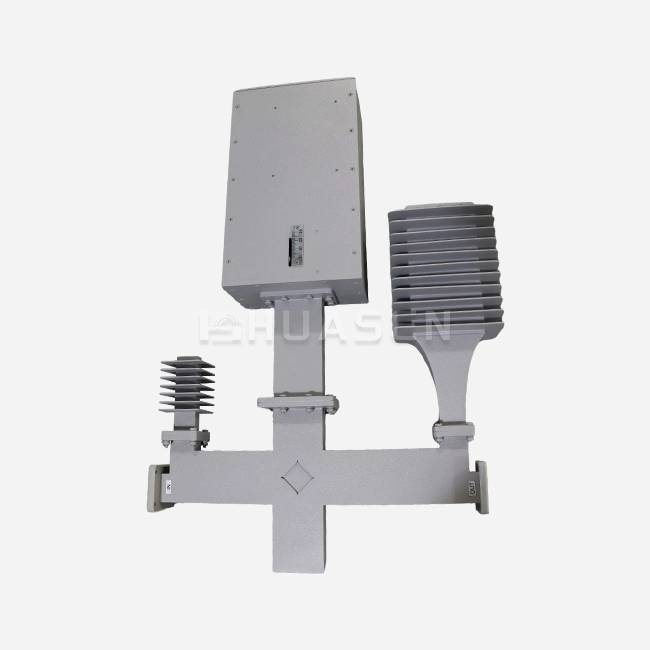
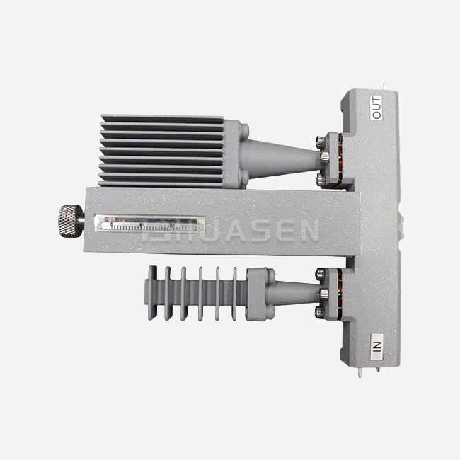
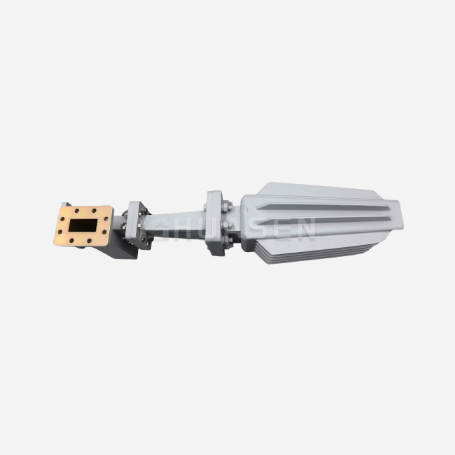
Huasen Microwave's mounting kits meet the exact needs of microwave labs and millimetre-wave systems, where mechanical errors have a direct effect on the accuracy of measurements. Our L-type and I-type brackets can hold antennas ranging in size from small patch arrays to 1.2-metre parabolic dishes. They can handle loads of up to 150 kg, which we know for sure by testing them destructively. Polarisation adjustment mechanisms let field techs improve cross-polarisation discrimination without taking the antenna off. This cuts the time needed for site visits by 40% compared to fixed-mount options. Customisation options include frequency-specific designs with waveguide connections and pressurisation fittings for microwave backup systems that work over long distances and operate at frequencies between 6 and 42 GHz.
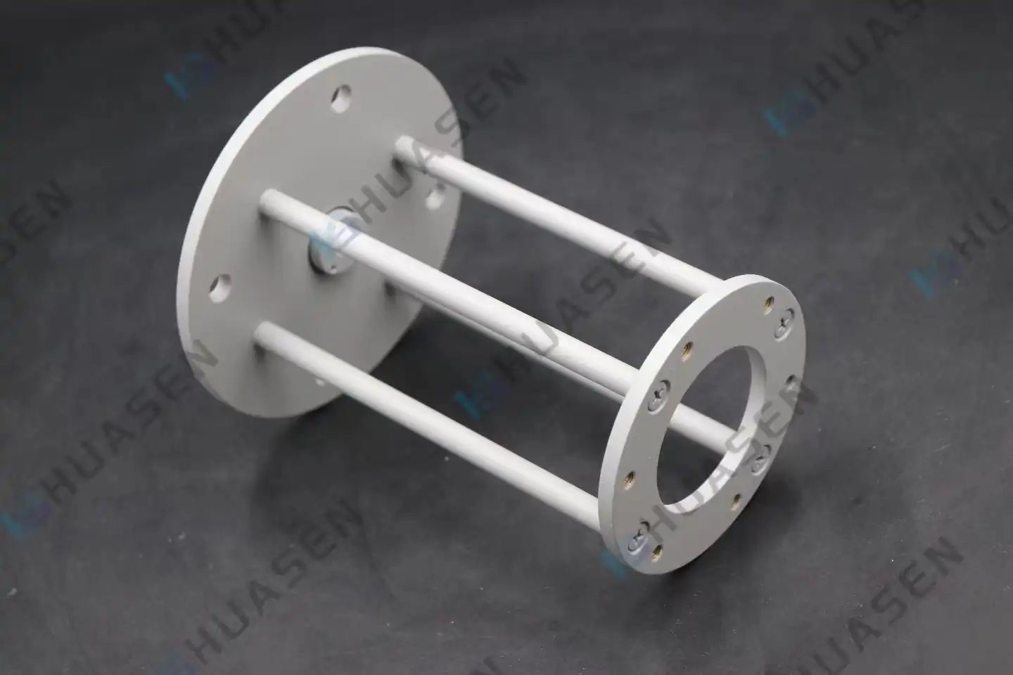
Professional fixing systems (antenna mounting brackets) are different from regular hardware because they have features for adjusting the height. With graduated scales marked in 1-degree steps and detent points every 5 degrees, optical surveying tools can be used to confirm the same position over and over. Locking mechanisms with two-sided locking plates spread compression forces evenly over 180 degrees of contact area. This keeps the parts from slipping under shock loads of up to 10G peak acceleration. When using a phased array, these design elements are very important because beam steering depends on the mechanical direction being exact to within 0.5 degrees across the operating temperature range.
Conclusion
The strength of the signal depends on how well the antennas are connected mechanically. Adjustable, long-lasting, and environmentally friendly mounting parts offer clear performance benefits, including lower VSWR, more stable radiation patterns, and longer service life. When buying things, putting certified materials, structural compliance, and expert help from suppliers at the top of the list can lower the total cost of ownership by lowering the need for upkeep and increasing system uptime. Companies that put in place 5G infrastructure, satellite terminals, or mission-critical communication links can gain a competitive edge by choosing professional-grade mounting options that keep RF performance high even in harsh operating conditions and over many years of service.
FAQ
1. What mounting structure type suits high-frequency millimetre-wave antennas?
Millimetre-wave systems that work above 24 GHz need very rigid mounting parts that keep mechanical movement below 0.1 mm so that beam alignment tolerances are met. Micro-movements that weaken signals in 5G and backhaul links can be stopped by I-type frames with strengthened gussets and precision-machined interfaces. Elevation devices that can be adjusted must have high-resolution detents that allow for field optimisation without adding play to the closing hardware. Huasen Microwave's small to medium-format units are designed to work with small antenna shapes and have load ratings high enough for radome-enclosed designs that can get ice buildup.
2. How does mounting height affect coverage patterns in base station deployments?
Through Fresnel zone clearing and downtilt optimisation, the coverage radius is directly affected by the antenna height. On flat ground, a line-of-sight range grows by about 13 km for every 10 metres of elevation gain. However, too much height leaves breaks in coverage in the near area. Adjustable mounting parts allow optimisation after installation, which takes into account differences in the terrain found during RF drive tests. Intermodulation performance is also affected by the distance between sector antennas. At cellular frequencies, a minimum distance of 0.75 metres is recommended to stop passive intermodulation products that lower receiver sensitivity.
Partner with Huasen Microwave for Superior Antenna Mounting Solutions
For RF operations to go well, the mounting assemblies need to meet the level of technical complexity and dependability needed by your system. Huasen Microwave has been making precise mounting solutions for telecom companies, military firms, and research institutions all over the world since 1993. Our L-type and I-type versions can be used for a wide range of tasks, from mmWave tests in the lab to installing base stations outside. They both have polarisation and elevation controls that can be changed. Customisation options help with special problems like high wind loads, extreme temperatures, and specific interaction needs. Our expert team can help you with application planning, load calculations, and fast sampling, whether you need small prototypes or large amounts for production. Contact sales@huasenmicrowave.com to talk about the details of your project and see what it's like to work with a company that specialises in Antenna Mounting.
References
1. Telecommunications Industry Association. (2018). TIA-222-H: Structural Standard for Antenna Supporting Structures and Antennas. Arlington, VA: TIA Publications.
2. Balanis, Constantine A. (2016). Antenna Theory: Analysis and Design, Fourth Edition. Hoboken, NJ: John Wiley & Sons.
3. Hall, Gerald J., and Stutzman, Warren L. (2020). Practical Antenna Handbook, Sixth Edition. New York: McGraw-Hill Education.
4. Institute of Electrical and Electronics Engineers. (2019). IEEE Standard for Safety Levels with Respect to Human Exposure to Radio Frequency Electromagnetic Fields, 3 kHz to 300 GHz. IEEE C95.1-2019.
5. National Electrical Manufacturers Association. (2017). NEMA TS 2: Traffic Controller Assemblies with NTCIP Requirements. Rosslyn, VA: NEMA Standards Publication.
6. Volakis, John L. (Ed.). (2007). Antenna Engineering Handbook, Fourth Edition. New York: McGraw-Hill Professional.
Send Inquiry