Single Channel Coaxial Rotary Joint: DC to 18 GHz Guide






2026-07-13 17:05:06
There's a secret problem that comes up when your radar antenna or satellite dish keeps tracking moving targets across the sky: how do you keep RF signals going without breaking cables? The Single Channel Coaxial Rotary Joint is the answer. It is a precision-engineered part that can rotate indefinitely around an axis while keeping the signal strong from DC to 18 GHz. This device gets rid of the need to wrap cables in dynamic systems, so transmissions can go on without interruption for mission-critical uses in defense, aircraft, and telecommunications. Working with RF systems for a long time, I've seen how this seemingly simple part can fix complicated engineering issues that would have otherwise put whole communication networks at risk.
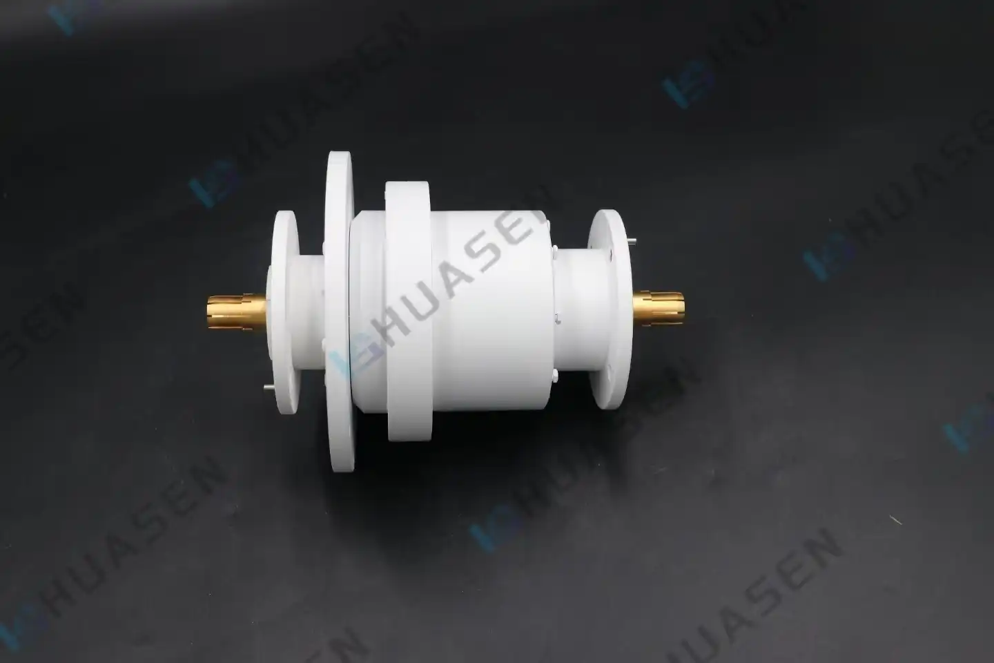
Understanding Single Channel Coaxial Rotary Joints
What Defines a Coaxial Rotary Joint?
A single-channel coaxial rotary joint is a very accurate, electrical-inactive part that sends radio frequency data between structures that are still and structures that are moving. This part works on transverse electromagnetic mode principles, which is different from normal slip rings that handle power or low-frequency data. It keeps its unique resistance, which is usually 50 Ω or 75 Ω, over a wide range of frequencies. The joint solves the major problem of cable fatigue in rotating assemblies, allowing them to keep rotating without the physical connections breaking down over time.
Core Operating Principles
It sends messages by having well-thought-out touch points that keep the electricity moving even when the gadget is turned off. Precision-machined center conductors are surrounded by shield elements on the outside and kept apart by special dielectrics inside the structure. As the rotor moves away from the stator, these materials keep the impedance matching the same. This part is great for broad uses since it can handle frequencies from DC to 18 GHz. Single-device options make it easy to set up a system and keep track of all of its parts.
Key Technical Specifications That Matter
When you test these joints, how well they work is directly affected by a number of things. Insertion loss is a way to measure how much data is lost through a device. All bands where the machine is used should have less than 0.2 dB of loss. The VSWR value tells you how well the resistance matches the voltage. If the value is less than 1.30:1, the signal will be returned as little as possible. When the signal needs to be protected, phase changes during spin, which are sometimes called "wow," must stay within ±1° to ±5°. Some models can handle 5,000 RPM, the amount of power that is needed, and the machine's size so that it can fit in places with limited room. Are all examples of mechanical specs?
Table 1: Technical Performance Parameters
| Parameter | Typical Value | Performance Impact |
|---|---|---|
| Frequency Range | DC to 18 GHz | Determines bandwidth compatibility |
| Insertion Loss | < 0.2 dB | Affects signal strength preservation |
| VSWR | < 1.30:1 | Influences reflection and efficiency |
| Phase Wow | ±1° to ±5° | Critical for coherent signal systems |
| Rotation Speed | Up to 5,000 RPM | Defines operational dynamics |
| Operating Temperature | -55°C to +85°C | Environmental adaptability range |
Single Versus Multi-Channel Variants
Different types of spinning joints can handle more than one type of data at the same time, but single-channel systems are better in many ways. It's easy to make them; they weigh less (often less than 30 grams), and spinning them takes less force. The small size makes it useful in places where there isn't much room to put it, like on UAV motion systems or small radar pedestals. It's trickier to set up multi-channel options because the wires need to be set up in a circle and spaced out far enough (usually more than 50dB) so that the channels can't talk to each other.
Applications and Benefits in B2B Industries
Radar Systems Integration
Radars used for weather surveillance and air traffic control depend on these joints to link fixed transmitters with antenna arrays that are always turning. The part works with high-power pulse signals and keeps the phase uniformity that is needed for accurate target recognition. I've seen systems where these parts work nonstop for years, sending peak power at the kilowatt level without any degradation. Being able to keep phase relationships fixed during spinning immediately leads to better radar clarity and the ability to tell targets apart.
SATCOM On-The-Move Terminals
These coaxial rotary joints are used in antenna pedestals for vehicle-mounted and maritime satellite communication systems. The antenna has to keep adjusting to track the satellites as the platforms move, which means that Ka, Ku, or X-band signals must always be sent. In this case, the rotating joint is where the stable receiver meets the moving antenna unit. This setup makes sure that voice calls, data links, and video streaming stay active no matter which way the vehicle is facing or how the ship is moving. Maritime workers really like the housing that doesn't rust and can handle sea spray and humidity.
Defense and Electronic Warfare
Components used in military applications must meet strict MIL-STD-810 weather requirements. These joints are used by electronic countermeasure systems on rotating turrets to send out jamming signals or listen in on communications over a wide range of frequencies. Wideband coverage from DC to 18 GHz lets a single device handle multiple working frequencies, which makes the system simpler. Beryllium copper contacts plated with gold-on-gold ensure low contact resistance even after millions of spinning cycles. This is very important for equipment that is used in rural areas, where servicing is hard to get to.
Cable Management in Remote Operations
These joints are built into cable management reels for deep-sea ROVs and oil exploration logging systems. The joint sends high-definition video and telemetry data from underwater equipment to control stations on the surface as the cable is put in or taken out. Sealing grades of IP65 or IP67 keep wetness and other contaminants from getting into internal parts. This app shows how choosing the right parts can directly affect how well an operation works—downtime for changing cables abroad costs a lot of money every hour.
In these fields, the real benefits include longer equipment life because cable flex fatigue is eliminated, shorter maintenance times compared to standard slip ring setups, and better signal quality preservation. One radar installer I talked to said that after moving to better quality coaxial rotary joints, there were 40% fewer calls for service in the field. This shows a clear return on investment (ROI) through higher dependability.
Comparing Coaxial Rotary Joints with Alternative Solutions
Slip Ring Limitations
Traditional slip rings are great at moving power and low-frequency data, but they don't work well for RF tasks above a few hundred megahertz. Their multi-contact brush designs have breaks in the resistance that cause microwave frequencies to cause signal echoes and loss. Slip rings can handle higher current loads, but coaxial rotary joints keep their 50Ω resistance, which is important for sending RF signals. It's easy to make a decision: slip rings are good for distributing power and low-speed data, while coaxial joints are better for keeping high-frequency signals stable.
Waveguide Rotary Joint Comparison
When millimeter waves are used, which are generally higher than 18 GHz, waveguide rotating joints do their job. The range that helical systems can handle is not this high. Square, rectangular, or round waveguides don't use coaxial conductors to send electromagnetic waves; instead, they use hollow metal channels. Waveguides can handle more power and go up to 110 GHz, but they have to be bigger and harder to line up mechanically. Since it works with frequencies in its range, the single-channel coaxial rotary joint DC-to-18 GHz wire is smaller and less expensive, making it the best choice for most internet systems.
Fiber Optic Rotary Alternatives
Fiber optic rotary joints, or FORJs, let two spinning surfaces send optical data to each other. They can handle electromagnetic radiation and have a huge amount of storage space. But at both ends, they need to be changed from electrical to optical. This adds to the complexity and cost of the system. Latency from conversion methods might not be okay in radar or RF tests. The coaxial rotary joints keep the phase relationships between the signals, which is important for coherent systems. They let RF signals pass through without being changed. Fiber has faster speeds, but coaxial choices are often chosen because they are easy to set up and have fewer parts.
Table 2: Rotary Joint Technology Comparison
| Technology | Frequency Range | Power Handling | Key Advantage | Primary Limitation |
|---|---|---|---|---|
| Coaxial Rotary Joint | DC to 110 GHz | Moderate to High | Wideband, compact | Frequency ceiling |
| Waveguide Joint | 18 GHz to 110 GHz | Very High | Extreme power | Larger size |
| Slip Ring | DC to 500 MHz | Very High Current | Multi-signal | Poor RF performance |
| Fiber Optic Joint | N/A (Optical) | Low (Signal Only) | EMI immunity | Requires conversion |
Selection and Procurement Guidelines for Buyers
Defining Your Technical Requirements
Successful procurement starts with a precise specification of operational parameters. Document your frequency range needs—does your system operate across the full DC to 18 GHz spectrum or a narrower band? Identify power handling requirements, both average and peak levels, especially for pulsed radar applications. Environmental conditions matter: outdoor installations need weatherproof enclosures rated IP65 or higher, while airborne systems require lightweight materials and vibration resistance per MIL-STD-810G standards.
Evaluating Supplier Capabilities
Established manufacturers like Pasternack, Moog, and Cobham offer proven track records in defense and aerospace markets. Their products typically include comprehensive test data showing measured insertion loss, VSWR, and phase performance across specified frequency ranges. Smaller specialized firms such as RotorTech or Mercotac may provide competitive pricing and faster customization turnaround. I recommend requesting sample units with calibration certificates for critical applications, allowing verification of specifications in your actual system environment before committing to volume purchases.
Customization Versus Off-the-Shelf
Standard catalog products suit many general applications, offering shorter lead times—often two to four weeks—and lower unit costs. Custom configurations become necessary when mounting interfaces require special flanges, frequency ranges need optimization beyond standard bands, or extreme environmental conditions demand unique sealing approaches. Custom development typically extends lead times to eight to twelve weeks and requires minimum order quantities. Balance your specific needs against budget constraints and project timelines when choosing between approaches.
Total Cost of Ownership Considerations
Unit price represents only part of the procurement equation. Calculate lifecycle costs, including installation labor, anticipated maintenance intervals, and replacement frequency. A lower-cost joint requiring annual replacement may exceed the total cost of a premium unit lasting five years. Factor in downtime costs for your application—a failed joint in a remote radar installation might cost more in service dispatch fees than the component itself. Suppliers offering extended warranties and responsive technical support add value beyond the purchase price.
Certification and Compliance Verification
Military and aerospace single-channel coaxial rotary joint applications often mandate compliance with specific standards. MIL-STD-348 covers waveguide and coaxial connector interfaces, while RoHS certification ensures restricted substance compliance for European markets. Request documentation proving conformance to relevant standards before finalizing orders. Some integrators I've worked with maintain approved vendor lists requiring third-party quality certifications like ISO 9001 or AS9100 for aerospace suppliers. Verify your organization's procurement requirements early to avoid delays.
Conclusion
Single-channel coaxial rotary joints operating from DC to 18 GHz represent essential components in modern RF systems requiring continuous rotation without cable entanglement. Their ability to maintain signal integrity through precise impedance matching, low insertion loss, and stable phase performance makes them indispensable in radar, satellite communications, and defense applications. By understanding technical specifications, comparing alternative technologies, and following proper selection guidelines, procurement teams secure components that optimize system reliability while controlling lifecycle costs. Regular maintenance, preserving contact quality and mechanical alignment, ensures these devices deliver years of uninterrupted service, justifying their role as critical infrastructure in demanding operational environments.
FAQ
1. What frequency ranges do these rotary joints support?
Single-channel coaxial rotary joints cover various frequency ranges depending on the connector types. SMA interfaces typically operate from DC to 18 GHz, while 2.92 mm connectors extend to 40 GHz, and 2.4 mm versions reach 50 GHz. The DC to 18 GHz range suits most broadband communication, radar, and electronic warfare applications, offering practical bandwidth for multi-frequency systems within compact form factors.
2. How do these differ from slip rings?
Slip rings transfer power and low-frequency signals through multiple brush contacts, suitable for applications below several hundred megahertz. Coaxial rotary joints maintain a constant 50Ω or 75Ω impedance through precision-machined coaxial structures, enabling microwave frequency transmission with minimal loss. Choose slip rings for power distribution; select coaxial joints for RF signal integrity.
3. What lead times should buyers expect?
Standard catalog units ship within two to four weeks from established suppliers. Custom configurations requiring specialized mounting flanges, unique frequency optimization, or extreme environmental sealing extend lead times to eight to twelve weeks. Rush orders may carry premium charges, so plan procurement around project timelines to avoid expediting costs.
4. Can these joints be customized for specific applications?
Most manufacturers offer customization of connector types, mounting interfaces, frequency ranges, and environmental sealing levels. Custom development typically requires minimum order quantities ranging from 10 to 100 units, depending on complexity. Provide detailed specifications, including mechanical drawings, frequency requirements, power handling needs, and environmental conditions, when requesting custom quotes to ensure accurate proposals.
Partner with Huasen Microwave for Superior Coaxial Rotary Joint Solutions
Huasen Microwave brings over three decades of RF engineering excellence to your rotating system challenges. As a specialized Coaxial Rotary Joint manufacturer since 1993, we deliver precision-engineered components meeting stringent performance standards for DC to 18 GHz applications. Our ISO-certified production facilities combine advanced machining capabilities with rigorous testing protocols, ensuring every unit meets specified insertion loss, VSWR, and phase stability requirements. We understand that aerospace, defense, and telecommunications projects demand more than catalog specifications—they require responsive technical support, flexible customization, and reliable supply chains. Our engineering team collaborates with your design requirements, offering sample validation, detailed test data, and application-specific optimization. Whether you need standard SMA-interface units for radar integration or custom maritime-rated assemblies for SATCOM terminals, we provide solutions backed by comprehensive documentation and competitive lead times. Contact our specialists at sales@huasenmicrowave.com to discuss your specific requirements, request technical datasheets, or obtain volume pricing for your next project. Discover how partnering with an experienced supplier transforms component procurement into a strategic advantage for your mission-critical systems.
References
1. Institute of Electrical and Electronics Engineers (IEEE), "Standard for Coaxial Connectors and Rotary Joints in Microwave Applications," IEEE Std 287-2007, Revised 2017.
2. Pozar, David M., "Microwave Engineering, Fourth Edition," John Wiley & Sons, 2012, Chapter 7: Impedance Matching and Tuning.
3. Military Standard, "MIL-STD-348A: Interface Standards for Coaxial and Waveguide Connections," United States Department of Defense, 2010.
4. Chatterjee, Rakhesh, "Advanced Microwave and Millimeter Wave Technologies: Semiconductor Devices, Circuits and Systems," InTech Publishing, 2010.
5. Smith, Carl A., "Rotary Joint Design for High-Frequency Radar Applications," Microwave Journal, Vol. 61, Issue 4, April 2018, pp. 78-92.
6. Balanis, Constantine A., "Antenna Theory: Analysis and Design, Fourth Edition," John Wiley & Sons, 2016, Section 12.8: Rotary Joint Considerations in Tracking Systems.
Send Inquiry