Signal Integrity in Multi Bend Waveguide






2026-07-28 10:40:38
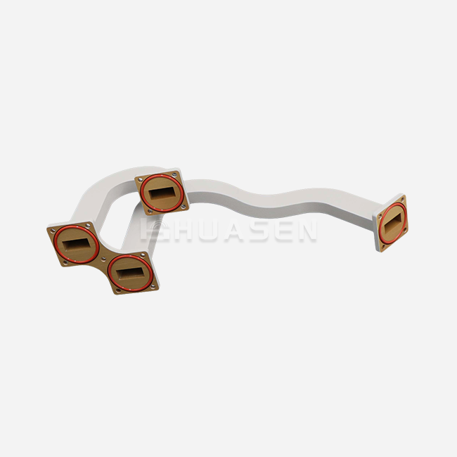
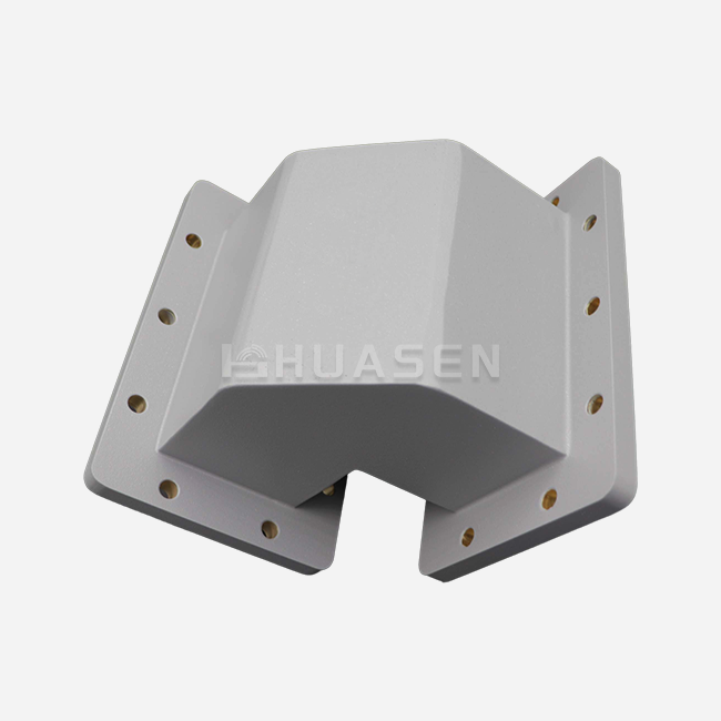
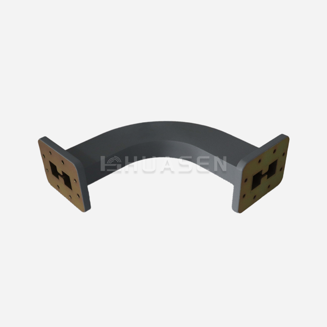
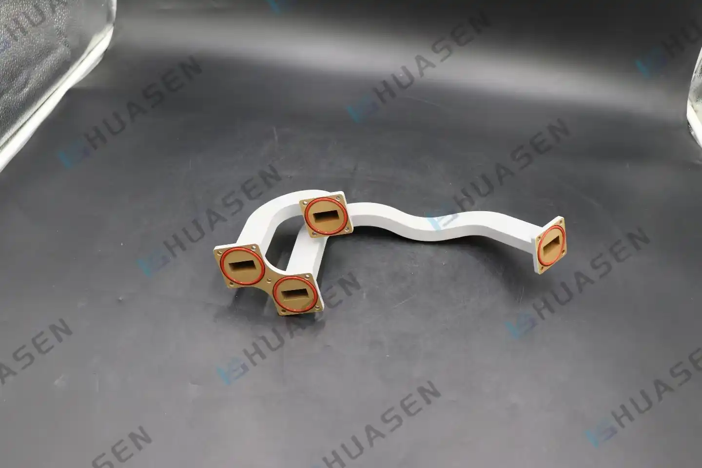
Signal integrity in multi-bend waveguide assemblies directly determines the reliability of high-frequency transmission in constrained RF systems. When electromagnetic waves navigate through complex bending geometries—combining E-plane and H-plane turns within a single rigid structure—maintaining low VSWR and minimal insertion loss becomes paramount. Unlike straight sections or flexible alternatives, these precision-engineered components eliminate multiple flange interfaces, reducing impedance mismatches and RF leakage while enabling seamless routeing through tight spaces in radar chassis, satellite payloads, and 5G base station architectures.
Understanding Signal Integrity Challenges in Multi-Bend Waveguides
Signal integrity is the most important factor in determining whether your microwave system sends correct data or experiences unpredictable decline. In multi-bend waveguides, where waves have to go through multiple changes in direction within a single assembly, the stakes are much higher than in straight gearbox paths.
Bend-Induced Losses and Mode Distortion
When an electromagnetic wave hits a bend, some of its energy either changes into higher-order modes or is lost as heat because the pairing isn't perfect. This effect is made worse by sharp turns, which create hot spots in certain areas that waste power and cause phase instability. When the bend radius drops below certain levels, the main TE10 mode (which is normal in rectangular multi-bend waveguides) can change into the TE20 or TE01 modes. Your VSWR readings will go up too high because these unwanted modes either weaken quickly or reflect back towards the source.
Reflection and Impedance Mismatch
Impedance discontinuities are naturally caused by abrupt geometric changes. If the characteristic impedance changes even slightly at a bend contact, some of the wave that comes in will bounce instead of going forward. This problem is made worse by multiple multi-bend waveguide bends because they cause constructive interference, which happens when signals that are mirrored line up in phase and greatly increase the standing wave ratios. When buying parts for 5G millimetre-wave fronthaul or Ka-band SATCOM systems, procurement teams can't stand this kind of uncertainty, because mirrored power not only wastes money on links but also has the potential to damage upstream amplifiers.
Material Attenuation Across Frequency Bands
The conductor material and its surface treatment significantly influence loss tangent behaviour. At X-band frequencies, oxygen-free copper plated with silver has better conductivity. But as you go up to W-band (75–110 GHz), even microscopic surface roughness from manufacturing processes becomes a major source of loss. Temperature coefficients are also important. For example, aluminium alloys are lighter than brass or copper, but their resistivity rises more quickly with heat, which could make performance less stable during high-power pulse transmission.
Analysing Multi-Bend Waveguide Design Principles to Enhance Signal Integrity
To get the best signal quality, engineers have to make decisions that balance electromagnetic theory with the facts of mechanics. Because design parameters interact in nonlinear ways, simulations must be done carefully before fabrication can begin.
Bend Radius Optimisation and Geometric Constraints
The waveguide cross-section of the multi-bend waveguide is directly related to the smallest bend radius that can be used. The WR-90 guide (X-band, 8.2–12.4 GHz) can handle smaller distances than the WR-28 guide (Ka-band, 26.5–40 GHz) because the wavelengths are smaller. Best practices in the industry say that to keep modal purity above 95%, bend angles should be at least 1.5 times the wider internal dimension. The engineering team at Huasen Microwave regularly improves these parameters by using electromagnetic modelling to change arm lengths and bending angles to fit the placement space of customers without affecting the electrical performance.
| Waveguide Standard | Frequency Range (GHz) | Recommended Min. Bend Radius (mm) | Typical Insertion Loss per Bend (dB) |
|---|---|---|---|
| WR-90 | 8.2–12.4 | 35 | 0.08–0.12 |
| WR-62 | 12.4–18.0 | 25 | 0.10–0.15 |
| WR-28 | 26.5–40.0 | 12 | 0.15–0.25 |
| WR-15 | 50.0–75.0 | 6 | 0.25–0.40 |
These numbers are what you can expect as a starting point. What happens depends on the quality of the finishing and how well the tolerances are followed.
Material Selection Balancing Conductivity and Mechanical Stability
When choosing the right base metal, you have to weigh the pros and cons of electrical performance, weight, thermal expansion, and cost. OFHC copper has the lowest resistive losses, but it also makes things heavier, which is not ideal for radar gimbals in the air or storage bays on spaceships. Even though aluminum 6061 is lighter, it needs stronger walls to match its rigidity, which could make the outside measurements bigger than what is allowed. Brass is in the middle because it can be machined easily to make complex shapes and still conducts electricity well when it is silver-plated. Surface treatments are just as important as the coating itself. Electroless nickel plating protects against corrosion for marine communications, while gold plating keeps the metal from rusting in humid, warm conditions or high-altitude places where condensation cycles happen.
Simulation Tools for Virtual Validation
Modern electromagnetic modeling tools, such as ANSYS HFSS, CST Microwave Studio, and COMSOL's RF Module, let you look at three-dimensional bend structures in full wave before you spend money on a prototype. In radar and electronic countermeasures, where millisecond rise times put a lot of stress on impedance matching, finite-difference time-domain (FDTD) methods are very important for capturing rapid behavior during pulse transmission. Beam Propagation Methods (BPM) are a good way to model almost-optical situations in millimeter-wave lines. They can predict phase front distortion through cascaded bends. So that independent testing can be done against MIL-STD-1347 or similar standards, procurement engineers should ask vendors to send simulation reports along with physical samples.
Advanced Fabrication Methods Enhancing Multi Bend Waveguide Performance
Precision manufacturing directly leads to signal integrity that can be predicted. Even small changes from the design specifications, like a 0.05 mm difference in wall thickness or a 0.2-degree misalignment, can cause resonant frequencies to shift and VSWR to rise.
CNC Bending and Electroforming Techniques
Mandrel bending machines that are managed by computers bend rectangular Multi Bend Waveguide tubes without changing the key internal cross-section. Huasen Microwave uses special fixtures that keep the dimensions accurate to within 0.03 mm even when the parts are bent many times. This is proven by inspecting them with a coordinate measuring machine (CMM) in line with ISO 9001 rules. Electroforming, a method in which metal deposits onto a precision mandrel, makes it possible to create complicated shapes that aren't possible with traditional machining. This is especially true for sub-WR-10 millimeter-wave guides, where making them by hand isn't practical. The one-piece design gets rid of internal joints, which are a common cause of passive intermodulation (PIM) distortion in high-power base station feeds.
Lithography and Additive Manufacturing for Emerging Bands
As the industry moves toward 6G frequencies (100–300 GHz), it becomes physically impossible to use traditional machines. Deep reactive-ion etching (DRIE) and micromachining on silicon make waveguide channels that are very precise, down to the micron level. These channels can be used in combined photonics hybrid systems. Selective laser melting (SLM) of aluminum or copper powders in metal 3D printing lets designers create bio-inspired bend geometries that nature naturally makes for low reflection. Surface roughness from additive processes currently limits Q-factors. However, post-processing steps such as chemical polishing and cold spray coating are slowly closing the performance gap between these assemblies and conventionally machined ones.
Tolerance Control and Yield Optimization
Tight tolerances cost more because they lead to more scrap and longer machining cycles. By loosening up on non-critical dimensions and tightening up on electrically sensitive parts, strategic tolerance distribution strikes a balance between cost and performance. As part of Huasen Microwave's quality control procedures, internal surfaces are inspected with a borescope, pressurized systems are tested for leaks up to 30 PSI, and a full two-port Vector Network Analyzer (VNA) characterizes the system from DC to 67 GHz. Every shipment comes with documented test data that makes it easy to track for aircraft projects that need to meet AS9100 standards.
| Specification Parameter | Standard Tolerance | Precision Tolerance | Impact on Performance |
|---|---|---|---|
| Flange flatness (μm) | ±25 | ±10 | Return loss, power handling |
| Internal dimension accuracy (mm) | ±0.08 | ±0.03 | Cut-off frequency, modal purity |
| Bend angle accuracy (degrees) | ±1.0 | ±0.2 | Phase match, VSWR |
| Surface roughness Ra (μm) | 1.6 | 0.4 | Insertion loss, PIM |
For phased array radar systems, where phase mistakes build up over hundreds of waveguide channels and lower the accuracy of beam guiding, tighter tolerances are a must.
Practical Guide to Procuring Multi-Bend Waveguides for Optimal Signal Integrity
To do procurement right, you need to look at more than just the datasheets. You also need to look at the skills of the seller, their customization processes, and their post-delivery support structures that keep project timelines safe.
Evaluating Suppliers Based on Technical and Commercial Criteria
Even though a brand's image is important, sometimes younger manufacturers with more up-to-date tools do better than older suppliers who are limited by old CNC tools. Ask for proof of recent MIL-STD or RTCA DO-160 certifications to show that quality control systems are more than just ISO 9001. Manufacturing capacity, which is shown in terms of units per month and the number of projects that can be worked on at the same time, tells you if a supplier can handle your growing business without affecting wait times. Customization services set commodity sellers apart from engineering partners. For example, being able to co-design bends from your CAD step files, model changes in performance, and make many prototypes quickly speeds up the development process.
| Vendor Capability | Tier-1 Multi Bend Waveguide Supplier | General RF Component Distributor |
|---|---|---|
| Custom geometry from CAD files | Full support | Limited/outsourced |
| In-house VNA testing to 67 GHz | Standard practice | External lab (delays) |
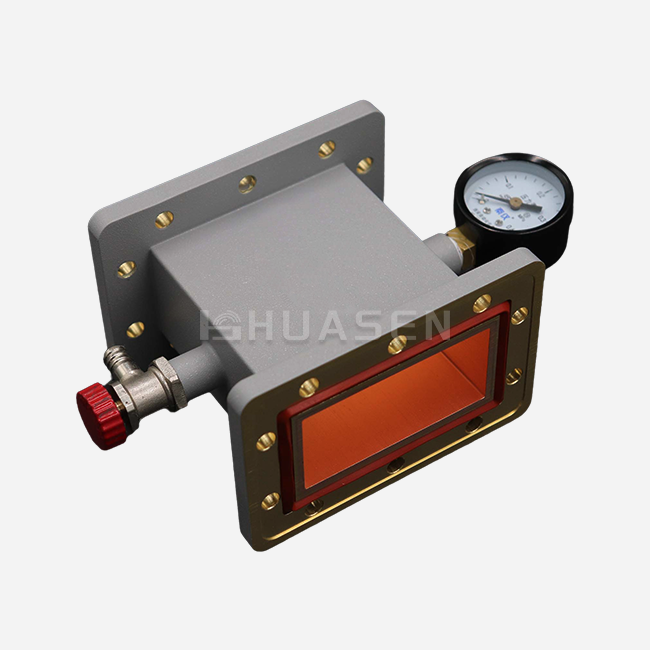
| Pressurization and leak certification | Integrated process | Not offered |
| Average custom lead time (weeks) | 4–6 | 8–12 |
Tier-1 suppliers like Huasen Microwave keep vertical integration, which means they do all of the bending, finishing, and testing under one roof. This keeps cooperation delays to a minimum.
Pricing Structures and Volume Discounts
The unit costs for custom multi-bend waveguide assemblies include one-time engineering (NRE) fees that are spread out over the number of orders. As tooling fixtures are used more than once, the price of a prototype WR-62 dual-bend assembly might go from $850 per unit at quantity one to $320 per unit at quantity fifty. Tiered pricing is unlocked by making a volume commitment. For example, yearly deals for 200 or more units often get 15–25% savings and priority booking during times of high demand. These terms of payment are not all the same. For example, military projects with long qualification cycles gain from milestone billing tied to first article inspections (FAI), while commercial 5G deployments prefer net-30 terms after delivery.
Managing Lead Times and Global Supply Chains
Catalogue bends usually ship in two weeks, but custom shapes can take anywhere from four to eight weeks, based on the plating lines and test backlog. Timelines can be cut down to three weeks with expedited services, which cost an extra 30–50% and prioritize machine access and weekend shifts. After 2020, supply chain robustness became more important. Dual-sourcing strategies reduce the risks of using a single supplier, but strict incoming inspection procedures are needed to keep things consistent across suppliers. Customers can pre-position inventory for phased deployments with Huasen Microwave's stocking plans. This helps with cash flow and makes sure that just-in-time access for integration benchmarks is maintained.
Conclusion
For mission-critical RF systems like 5G infrastructure, satellite networks, and defense radar platforms, signal integrity in multi-bend waveguide assemblies is still a must. When procurement workers understand how bend geometry, material properties, and manufacturing quality affect each other, they can choose parts that meet the needs of both electrical performance and mechanical installation. Rigid multi-bend waveguide designs get rid of the cascading losses and phase instability that come with flexible options. They also combine what would normally need many flanged sections into streamlined, reliable units. As frequency bands move toward millimeter waves and terahertz ranges, it becomes important to work with providers who put money into advanced modeling, precise manufacturing, and thorough testing in order to keep system performance competitive.
FAQ
1. What causes signal loss in multi-bend waveguide structures?
Signal loss is mostly caused by three things: resistive heating in the circuit walls (I² losses), mode conversion at bends where the main TE10 mode changes into higher-order modes, and radiation leaks through joints that aren't perfectly sealed or that aren't the right size. The amount of loss is greatly affected by the bend radius. Radii less than 1.5 times the waveguide width cause loss to rise exponentially. Conductivity of the material and the finish on the surface are also very important. For example, silver plating lowers loss by 15–20% compared to raw aluminum at X-band frequencies.
2. How do I specify bend angles and arm lengths for custom applications?
Giving your provider a 3D STEP or IGES CAD file will make sure that they understand the space constraints correctly. Include the angles of the flanges, the bolt hole shapes that must meet MIL-DTL-3922 or EIA standards, and any requirements for sealing against the environment. Give the operating frequency range, the highest VSWR that is allowed, and the power handling needs. Before making tooling fixtures, Huasen Microwave's engineering team looks over these inputs, suggests the best bend radii, and gives back simulation-based performance predictions.
3. Can multi-bend waveguides handle high-power pulse transmission?
Yes, if it's designed right. Waveguide size, pressurization, and bend quality all affect how much power they can handle. A WR-90 guide that is pressurized to 15 PSI with dry nitrogen can safely send 50 kW of peak power at X-band, as long as the bend radius is greater than the minimum and there are no sharp breaks that cause voltage concentration points. For arc detection to work, the inside surface usually needs to be smoother than 0.8 μm Ra. This can be done by electropolishing or diamond turning after the part has been made.
Explore Huasen Microwave's Customizable Multi-Bend Waveguide Solutions.
Huasen Microwave is ready to turn your tricky RF routing problems into dependable, top-notch multi-bend waveguide systems. Since 1993, our team has been working in microwave engineering and specializes in creating multi-bend waveguide configurations that are exactly right for your power needs, frequency bands, and space limitations. We allow for easy changes to be made to bending angles, arm lengths, interface specifications, and even sealing solutions for multi-bend waveguides for high-power uses. Our vertically integrated production makes sure that the quality stays the same from the first modeling to the final VNA testing, whether you need WR-90 assemblies for 5G base stations or precise WR-28 bends for satellite packages. Email our applications engineers at sales@huasenmicrowave.com to talk about the needs of your project, ask for sample parts, or get detailed quotes. As a reliable multi-bend waveguide maker, we offer products that are certified by MIL-STD, RoHS, and aerospace organizations. We also keep our wait times low for both prototypes and full production runs.
References
1. Marcuvitz, Nathan. Waveguide Handbook. IET Electromagnetic Waves Series, 1986.
2. Pozar, David M. Microwave Engineering, 4th Edition. Wiley, 2011.
3. Collin, Robert E. Field Theory of Guided Waves, 2nd Edition. IEEE Press, 1991.
4. Saad, Theodore S. Microwave Engineers' Handbook, Volume 1: Components and Mechanisms. Artech House, 1971.
5. Montgomery, C. G., Dicke, Robert H., and Purcell, Edward M. Principles of Microwave Circuits. MIT Radiation Laboratory Series Vol. 8, 1948.
6. Lewin, Leonard. Advanced Theory of Waveguides. Iliffe & Sons, 1951.
Send Inquiry