What Are the Key Specifications of a Waveguide Short Plate?






2026-07-28 10:40:32
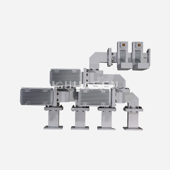
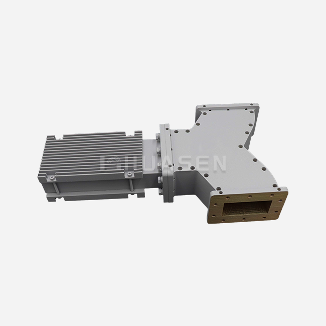
A waveguide short plate is a precision-engineered termination component designed to reflect electromagnetic energy within RF and microwave transmission systems. Key specifications include operating frequency range (0.32 GHz to 112 GHz), VSWR performance (≥60 for fixed types, ≥50 for sliding variants), material composition (aluminum with anodized finish for lower frequencies, copper with silver or gold plating for higher frequencies), structure type (fixed, sliding, or bias configurations), flange compatibility (FDP/FBP/FUGP), and mechanical tolerances. These specifications directly impact system calibration accuracy, power handling capacity, and long-term reliability in demanding industrial environments.
Understanding Waveguide Short Plates: Function and Application
What Is a Waveguide Short Plate, and How Does It Work?
A waveguide short plate functions as a precise metal block put at the end of a waveguide transmission line. It creates a reflection coefficient that is very close to 1. Instead of absorbing electromagnetic energy like matching loads do, these termination devices set up a reference plane where voltage is zero and current is maximum. Because of this basic behavior, they are required to set known resistance states during the testing of network analyzers.
The physical mechanism is made up of highly conducting metal surfaces that are placed perpendicular to the direction of wave propagation. These surfaces are usually made of copper or aluminum with special platings. When electromagnetic waves hit this barrier, they are completely reflected and their phase shifts by 180 degrees. How close the device is to perfect short-circuit behavior depends on how flat the contact surface is and how conductive the plate material is. This is especially true at millimeter-wave frequencies, where skin depth is very important.
Core Applications Across Industries
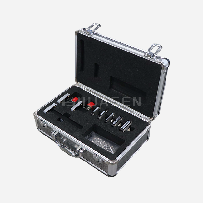
These parts make up the "Short" standard in TRL (Thru-Reflect-Line) and SOLT (Short-Open-Load-Thru) calibration kits used in labs. They are used by metrology engineers to mathematically get rid of regular mistakes in measurement setups. This lets them accurately describe the devices being tested. The accurate reference plane they set has a direct effect on the measurement uncertainty in making antennas, tuning filters, and testing amplifiers.
Another difficult area of application is telecommunications infrastructure. When the base station is being set up or serviced, waveguide ports that aren't being used need to be properly terminated to stop electromagnetic interference from getting out. This is done by short plates, which also let techs check the performance of the circulator isolation under full reflection circumstances. Because these devices produce a high VSWR, they can find impedance gaps or worn-out connectors that might not have been seen otherwise.
Defense and aerospace systems utilize these components in radar tuning and electronic countermeasure tools. In particle accelerator facilities, sliding short setups are used to change the frequencies of cavity resonators. This accounts for temperature drift in high-power RF systems. Because they can exactly control the length of an electrical cable by moving it around, they are useful in situations where set parts can't adapt to changing working conditions.
Advantages Over Alternative Termination Methods
When you use short circuits instead of resistive loads, you don't have to worry about the heat loss that comes with receiving high-power signals. In tests, this feature is useful because it means that mirrored power goes back to the secured source equipment instead of heating up the termination itself. Not having any resistive parts also gets rid of any possible failure modes that could be caused by thermal cycling or going over the power limit.
When compared to open-circuit terminations, waveguide short-plate short plates are more consistent and less affected by external factors. Open ends have fringing field effects that change depending on the humidity and conductive objects nearby, but a short plate's solid metal barrier keeps its electrical properties the same. This stability means that calibration references are more reliable and the system will behave in a predictable way when it is deployed in the field.
Key Technical Specifications of Waveguide Short Plates
Frequency Coverage and Electromagnetic Properties
The most basic characteristic is the operating frequency range, which tells you which waveguide standards the Waveguide Short Plate supports. Modern designs cover frequencies from 0.32 GHz to 112 GHz, which can be used for a wide range of tasks, from UHF monitoring systems to E-band backup lines. Each frequency band has its own waveguide measurements, ranging from WR-2300 for the lowest frequencies to WR-10 for millimeter-wave applications. The short plate's physical dimensions perfectly fit these standards.
How close the device is to ideal short-circuit behavior is determined by its reflection characteristics. VSWR (Voltage Standing Wave Ratio) is the main measurement, and values ≥60 for fixed short plates and ≥50 for sliding configurations mean that the device works very well. These numbers mean that the reflection coefficients are higher than 0.983, which means that less than 1.7% of the energy that hits the surface doesn't rebound because of resistance losses or changes in impedance. Higher VSWR values are very important for precision measuring tasks that depend on known reference standards for accurate measurements.
Material Composition and Surface Treatments
Material selection directly impacts both electrical efficiency and environmental longevity. In lower frequency uses (below 18 GHz), where skin depth lets enough current flow through the oxide layer, aluminum metals with anodized finishes are most common. Anodizing gives metals the corrosion protection they need for outdoor installations in marine or coastal settings. This helps base station operators and maritime communication systems deal with worries about how well their systems can change to different environments.
Copper construction is needed for higher frequencies because it conducts electricity better. Silver-plated has the lowest surface resistance, which lowers ohmic losses that become more important as frequency goes up and skin depth goes down. But silver oxidizes when it comes into contact with sulfur compounds in the air, which makes it more resistant over time. This problem can be fixed with gold plating, which gives stable long-term performance in labs and space applications where replacing parts is not possible. The thickness of the metal is usually between 3 and 10 micrometers, which strikes a balance between cost and performance needs.
Table 1: Material Properties and Frequency Suitability
| Material/Plating | Conductivity (MS/m) | Recommended Frequency Range | Primary Advantages | Typical Applications |
|---|---|---|---|---|
| Aluminum (Anodized) | 37.7 | 0.32–18 GHz | Corrosion resistance, cost-effective | Outdoor base stations, maritime systems |
| Copper (Silver-plated) | 63.0 | 18–112 GHz | Highest conductivity, minimal loss | Laboratory calibration, high-precision testing |
| Copper (Gold-plated) | 45.2 | 18–112 GHz | Oxidation resistance, stability | Space systems, long-term installations |
Structural Configurations and Mechanical Design
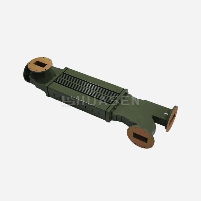
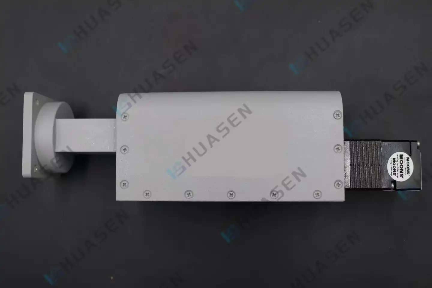
There are three main types of structures that meet different operational needs. Fixed Waveguide Short Plates (WS) offer stable ends with the best VSWR performance, making them perfect for use as standards for calibration and as steady reference planes. Their simple design means that there are no worries about mechanical wear, which is good for long-term steadiness in measurement applications.
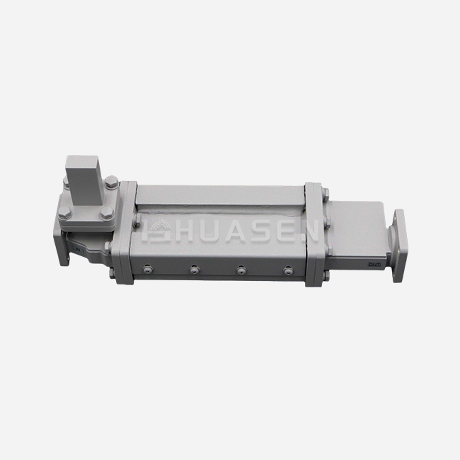
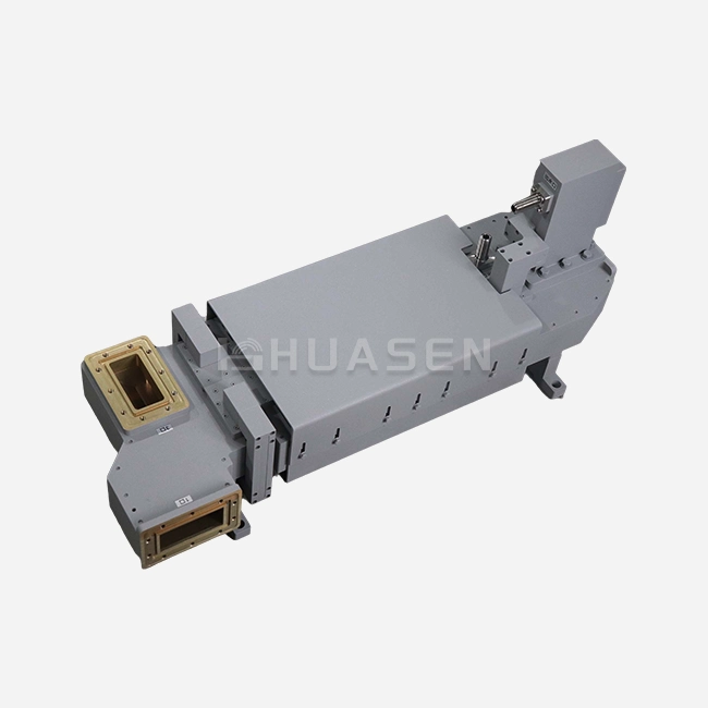
Precision linear bearings are built into Sliding Waveguide Short Plates (WSS), allowing position adjustment over a range of 10 to 300 millimeters. This flexibility lets you tune the stubs and change the phase, which is useful for improving resonant cavities and building impedance matching networks. When VSWR is compared to fixed designs, the mechanical complexity makes it a little worse, but the operating freedom usually makes up for this tradeoff in lab and development settings.
Bias Waveguide Short Plates (WOFS) represent specialized variants designed for systems requiring DC isolation between circuit sections while maintaining RF short-circuit characteristics. These findings apply to amplifier bias networks and active antenna systems where control voltages must not propagate through waveguide sections.
Flange Standards and Interface Compatibility
The types of flanges affect how well they work with current waveguide systems. Flat Differential Pressure (FDP) flanges are good for general-purpose uses, while Flat Bolted Pressure (FBP) types make things more rigid in places with a lot of vibration, like overhead radar systems. FUGP (Flat Universal Gauge Pressure) setups can be used in labs where precise alignment is needed.
Custom flange standards take into account specific fitting issues, like when there isn't much room in a case or when the waveguides aren't oriented in the usual way. Waveguide short-plate solutions also require consideration of these fitting issues. To make sure the right integration, mounting hole patterns, bolt sizes, and gasket groove dimensions must all be carefully checked during procurement. A lot of providers, including makers that can do a lot of customization, offer modification services to make standard designs fit certain mechanical connections.
Comparing Waveguide Short Plates with Alternative Components
Functional Distinctions from Matched Loads
Matched loads take in energy that comes in through resistive elements, turning RF power into heat while showing the waveguide's characteristic resistance. Because this method of termination stops reflections, loads are perfect for keeping signal sources safe and getting rid of standing waves in transmission systems. But the applications where they can safely work are limited by how much power they can handle, and the size and weight limitations caused by the need to dissipate heat are also present.
The reverse is true for waveguide short plates; they increase echoes instead of decreasing them. This behavior works well for calibration methods where known standards for reflection allow error-correcting techniques to work. When resistive elements are removed, thermal limits on power handling are removed. However, the source equipment must be able to handle full reflected power. System makers choose between these methods based on whether they need to get rid of shadows or make them on purpose.
Comparison with Open-Circuit Terminations
Open-circuit terminations leave the ends of the waveguides free, which creates high-impedance boundaries that cause reflections. Even though they are easy to think about, open terminations have a lot of problems in real life. The fringing fields that go beyond the waveguide opening interact with structures nearby, changing the reflection coefficient in ways that make it harder to get an accurate reading. The electrical qualities of air gaps are changed by things in the environment, like humidity, which makes measurements less accurate.
Because their reference lines are physically defined, short circuits offer better accuracy. The metal-to-metal touch sets the limits, regardless of the electromagnetic surroundings outside. Because of this, all manufacturers of calibration kits choose short plates over open terminations, even though the latter is easier to put together. When it comes to calibration accuracy or weather stability, procurement requirements should make it clear that open-circuit options are not acceptable.
Table 2: Component Type Comparison Matrix
| Component Type | Reflection Magnitude | Primary Function | Power Handling | Environmental Sensitivity | Calibration Suitability |
|---|---|---|---|---|---|
| Short Plate | ~100% (VSWR ≥50) | Create known reflection | Unlimited (passive) | Low | Excellent |
| Matched Load | <1% (VSWR <1.2) | Absorb energy | Limited by thermal rating | Medium | Poor |
| Open Termination | ~100% (variable) | Provide high impedance | Unlimited (passive) | High | Poor |
Compatibility Considerations with System Architecture
Waveguide size compatibility is the most important thing to think about when choosing components. A WR-90 short plate and WR-62 flanges can't fit together physically, and trying to force them to fit hurts the precision-matching surfaces. When engineers buy a part, they have to make sure that the waveguide name fits the standard for their system's gearbox line at all connection places.
Compatibility in the frequency range goes beyond the physical dimensions. Even if the ring sizes are the same, using a part outside of its intended frequency range can lead to uncertain outcomes. When the range is below what is suggested, the waveguide works in cutoff mode with too much loss. Higher-order modes spread above the given range, creating interference patterns that make calibration methods and measurement data useless. Reliable providers make it clear what the waveguide standard is and what frequency range can be used. This makes it easy to check against system requirements. The waveguide short plate is also designed to meet specific frequency requirements, ensuring stable performance within the applicable range.
Conclusion
To choose the right waveguide short plates, you have to weigh a lot of scientific details against the needs of the application and the limitations of the buying process. When you know how frequency range, VSWR performance, material makeup, and structural design affect system performance, you can make smart choices that improve both short-term functionality and long-term dependability. Fixed, sliding, and bias configurations are different because they meet different operational needs, such as those that need precise calibration or adaptive tuning.
Material and plating choices directly influence environmental durability and electrical performance, with aluminum anodizing serving outdoor installations and copper with precious metal plating supporting high-frequency laboratory work. Flange compatibility and customization capabilities ensure mechanical integration, while supplier evaluation criteria encompassing quality certifications, delivery reliability, and technical support determine procurement success. Proper installation and maintenance procedures protect your investment, delivering consistent performance throughout the component lifecycle.
FAQ
1. What frequency range do waveguide short plates typically cover?
Modern designs work at frequencies between 0.32 GHz and 112 GHz, but different waveguide short plates only work at certain frequencies that match waveguide standards. Waveguides with lower frequencies, like WR-2300, are bigger, while standards with millimeter waves, like WR-10, are smaller. Make sure that the frequency range given for the component covers your whole operational band plus some extra space.
2. How do I determine the correct waveguide size for my short plate?
Match the waveguide standard designation exactly—a WR-90 system needs WR-90 parts. The cutoff frequency, physical measurements, and lip patterns must all match up. Suppliers offer compatibility charts that connect frequency bands to waveguide standards, which makes it easier to choose.
3. Can standard short plates handle high-power applications?
Short plates mirror power instead of soaking it, which gets rid of the problems caused by heat loss. Your source equipment's ability to handle mirrored power is now the maximum. Before putting short plates in high-power systems, make sure that the transmitter protection circuits can handle full reflection.
4. Why does surface plating matter for these components?
At microwave frequencies, electricity can only flow through the skin up to a few micrometers deep. So, efficiency is based on surface conductivity. Silver has the least resistance, but it tarnishes. Gold, on the other hand, is stable. The choice weighs the needs for long-term stability, environmental exposure, and electricity performance.
Partner with Huasen Microwave for Your Waveguide Short Plate Requirements
Huasen Microwave Technology Co., Ltd. has been making high-frequency parts for more than 30 years and can provide waveguide short plates that meet the strict requirements of applications in defense, aerospace, and telecommunications. Our product line includes all frequencies from 0.32 GHz to 112 GHz, with fixed, slide, and bias configurations. For fixed types, the VSWR performance is more than 60. As a well-known company that makes waveguide short plates, we keep all of our certifications up-to-date, including those for MIL-STD and RoHS. We also offer a lot of customization options for different flange setups and frequency ranges.
Email our engineering team at sales@huasenmicrowave.com to talk about your specific needs, ask for technical documentation, or get quotes for both prototypes and full production runs. Our quick expert help makes sure you get parts that are perfectly matched to the needs of your application. This is backed up by thorough testing and quality assurance.
References
1. Pozar, David M. "Microwave Engineering, 4th Edition." John Wiley & Sons, 2012.
2. Balanis, Constantine A. "Advanced Engineering Electromagnetics, 2nd Edition." John Wiley & Sons, 2012.
3. "MIL-STD-3922: General Requirements for Waveguide and Coaxial Transmission Line Components and Assemblies." U.S. Department of Defense, 2018.
4. Collin, Robert E. "Foundations for Microwave Engineering, 2nd Edition." IEEE Press, 2001.
5. Rytting, Doug. "Network Analyzer Error Models and Calibration Methods. "Keysight Technologies Application Note, 2016.
6. IEEE Standard 291-2018: "IEEE Standard Methods for Measuring Electromagnetic Properties of Waveguide and Transmission Lines." Institute of Electrical and Electronics Engineers, 2018.
Send Inquiry