What Is TRL Calibration in a Waveguide Calibration Kit?






2026-07-28 10:40:34
TRL (Thru-Reflect-Line) calibration represents a sophisticated error-correction technique specifically designed for precision measurement in waveguide systems. When engineers work with vector network analyzers (VNAs) to characterize microwave and millimeter-wave components, TRL calibration within a waveguide calibration kit removes systematic measurement errors by establishing an accurate reference plane. This method uses three precisely machined standards—a thru connection, a reflective termination, and a transmission line section—to mathematically de-embed directivity errors, source match errors, and reflection tracking errors. The result is measurement data that truly reflects your device under test rather than artifacts from test fixtures, making TRL calibration indispensable for frequencies above 18 GHz where coaxial methods introduce unacceptable uncertainties.
Understanding TRL Calibration in Waveguide Calibration Kits
The Core Components of TRL Calibration
TRL calibration relies on three basic standards. These standards work together to fully describe measurement system errors. The Thru standard sets up a baseline phase reference by making a link between the two VNA test ports that is either of known length or of zero length. The Reflect standard gives a known reflection coefficient at both ends. It is usually a precision short plate with VSWR ≥ 60. The Line standard adds a set length of transmission line, usually 1/4λ or 1/8λ sections, which lets the VNA figure out the characteristic resistance and propagation constant.
These parts solve the special problems that come up when measuring waveguides, like when non-TEM propagation modes make normal coaxial calibration methods useless. Precision machining tolerances on these standards have a direct effect on measurement uncertainty. That's why high-quality kits use materials like tellurium copper that have been plated with gold or silver to keep the dimensions stable and reduce skin-effect losses over a wide frequency range.
Why TRL Calibration Matters for High-Frequency Applications?
Accurate measurements are very important when your team is working on 5G backhaul systems or satellite communication parts that work at Ka-band (26.5-40 GHz) or even W-band (75-110 GHz). At these frequencies, a coaxial connector adds insertion loss of more than 2 dB per connection and causes phase errors that hide how well your component really works. This is fixed by TRL calibration, which moves the reference plane straight to the waveguide interface. This gets rid of these unwanted effects.
It works especially well for figuring out how amplifiers, filters, and antenna feed networks work when insertion loss measurements need to be able to pick up differences as little as 0.1 dB. According to research from the National Institute of Standards and Technology (NIST), TRL calibration can achieve magnitude uncertainty below ±0.15 dB and phase uncertainty within ±1.5° across millimeter-wave bands. These are performance levels that can't be reached with SOLT methods at these frequencies.
Frequency Range and Accuracy Considerations
TRL calibration keeps measurements accurate over a very wide range of frequencies. The WR-90 waveguide kit works in the X-band (8.2-12.4 GHz), while the WR-15 kit goes into the V-band (50–75 GHz). The great thing about this method is that it works at any frequency. This is different from load-based calibrations, which don't work as well at higher frequencies because of parasitics. Instead, TRL calibration uses transmission line theory, which works consistently across decades of bandwidth.
When buying teams, look at accuracy; they have to look at things like flange flatness (usually better than 5 micrometers), pin depth accuracy, and the quality of the gold finishing on the surfaces that fit together. These technical factors have a direct effect on how well the electricity works. A well-kept waveguide calibration kit from a reputable company adds less than 0.02 dB to the overall measurement uncertainty budget. This means that your team can confidently test parts against strict requirements for radar cross-section analysis or material characterization tasks.
Comparing TRL Calibration with Other Waveguide Calibration Methods
TRL Versus SOLT: Fundamental Principle Differences
SOLT (Short-Open-Load-Thru) tuning is common in coaxial systems, but it has problems when used in waveguide settings. The technique needs an open standard, which is not possible in waveguide designs because an open waveguide sends energy into space instead of reflecting it back. Using a spreading lip to try to get close to an open causes big modelling mistakes above 20 GHz.
A single-line standard is used instead of the problematic open and load standards in TRL calibration, which is a very elegant way to get around this problem. The mathematical beauty is in the way that TRL gets the characteristic impedance from the recorded parameters of reflection and transmission for all three standards, without needing to know the termination impedance first. Because it can adjust itself, TRL is naturally more resistant to differences in components and the effects of time.
When measuring active parts like power amps, the real effect becomes clear. SOLT calibration at 28 GHz might get an error of ±0.5 dB, but TRL calibration in the same settings gives an error of ±0.15 dB, which is three times better and lets you find small differences in performance between runs of products.
When TRL Outperforms Alternative Methods
TRL calibration is clearly better in a number of serious situations. When studying low-loss dielectric materials for radome uses, TRL's better directivity correction makes it possible to measure permittivity values accurately with errors of less than 2%. Because SOLT calibration isn't very good at directing light, it could add 5-8% of uncertainty to the readings, making them unsuitable for aircraft qualification tests.
When other methods fail in harsh environments like thermal vacuum chambers that simulate spacecraft deployment or climatic chambers used to test maritime radar components, TRL calibration keeps the accuracy. The three standards are mechanically simple, which reduces thermal expansion mismatches. Also, they don't have any lossy load elements, which gets rid of the temperature-dependent absorption changes that make SOLT calibrations hard to do.
The following table shows how key performance indicators differ across popular testing methods:
| Method of Calibration | Range of Frequencies (GHz) | Uncertainty in Magnitude (dB) | Uncertainty in Phase (degrees) | Sensitivity to the Environment |
|---|---|---|---|---|
| TRL | 1-110+ | ±0.10 to ±0.20 | ±1.0 to ±2.0 | Low |
| SOLT | 0.01-67 | ±0.30 to ±0.60 | ±3.0 to ±6.0 | Moderate |
| LRL | 1-110+ | ±0.15 to ±0.25 | 1.5 to 2.5 | Low |
| Coaxial Adapter Method | 0.01 to 50 | ±0.40 to ±1.00 | ±4.0 to ±10.0 | High |
Selection Criteria for Your Application
Managers of procurement should make sure that the testing method fits the needs of their operations. If you need to test broadband components across multiple waveguide bands, like in the development of multi-band radars, buying multiple TRL Waveguide Calibration Kits optimized for each band will give you better results than using a single universal SOLT kit. The higher starting cost is worth it because the better accuracy cuts down on product development cycles and lowers waste by making pass/fail decisions with more confidence.
Teams with limited funds might think about using a mix of methods. For important measurements where accuracy is key to the success of the program, like antenna pattern verification, filter tuning validation, and amplifier linearity assessment, use TRL calibration. For basic screening measures, use faster SOLT methods. This approach strikes a good mix between keeping throughput high enough for regular testing and improving measurement quality where it matters most.
Procurement Guide: Buying the Right Waveguide Calibration Kit with TRL Capability
Critical Evaluation Parameters for B2B Buyers
When choosing a precision waveguide calibration kit, you need to pay close attention to the details that affect how well you can measure over time. Picking the right materials is the first step. Look for kits made from oxygen-free copper alloys or Invar, which have thermal stability values below 2 ppm/°C. The quality of the plating is just as important. The thickness of the gold plating should be more than 2.5 micrometers to keep it from wearing through when connected over and over, and the silver plating needs to be maintained every so often to keep it from tarnishing.
Professional-grade equipment is different from consumer products because it comes with documentation about its dimensions. Manufacturers with a good reputation offer approved flange flatness readings that can be tracked back to national metrology institutes like NIST or NPL. To make sure that electromagnetic modes can travel properly and that readings above 50 GHz are accurate, the dimensions of the waveguide opening should stay within ±0.013 mm (±0.0005 inches).
Verifying compatibility stops mistakes in buying that cost a lot of money. Make sure the adapters in the kit work with the connectors on your VNA. For example, many recent analyzers use 2.4 mm or 1.85 mm coaxial connectors, which need specific adapter setups. The 1/4λ, 1/8λ, and 3/8λ precision waveguide sections must cover the frequency range of the uses you want to use them for, and the kit should be able to be expanded in the future if you plan to move into nearby frequency bands.
Manufacturer Landscape and Value Propositions
There are a lot of well-known companies that make testing kits whose goods have been used in tough situations before. Leaders in the industry offer complete kits that cover waveguide bands from WR-430 (1.7–2.6 GHz) to WR-10 (75–110 GHz). Each kit comes with all the standards needed for a full 12-term error correction. Most of the time, these companies have production facilities that are ISO 9001 certified and give out calibration certificates that can be tracked back to international standards.
New suppliers coming from places that are good at making things now fight on quality as well as price. Some offer modular kit setups that let procurement teams buy only the standards they need for immediate use. This lowers the initial capital spending while keeping the paths for upgrades open. This adaptability is appealing to new businesses making specialized millimeter-wave goods or to research organizations with limited funds.
When looking at suppliers, find out what kind of expert help they offer. The best waveguide calibration kit provider will help you with application engineering so that you can make the most of the calibration steps for your specific measurement problems. Suppliers who care about their customers' success are different from those who just sell goods. Suppliers who care about their customers' success give them access to measurement uncertainty budgets, thorough standard meanings for VNA entry, and quick repair of damaged parts.
Pricing Structures and Lead Time Considerations
The price of a calibration kit changes a lot depending on the frequency range and level of accuracy. A basic WR-90 kit for measuring in the X-band range could cost between $8,000 and $12,000. A high-precision W-band (WR-10) kit with specs for error levels below 0.1 dB can cost more than $45,000. The cost of the investment is due to the need for very precise machining at millimeter wavelengths, where a 1-micron error in size can cause a big drop in electrical performance.
People who buy a lot of things should talk about multi-band bundle prices. When you buy calibration kits for three adjacent waveguide bands at the same time, you can often save 15–20% compared to buying them separately. Extended guarantee coverage is something that should be thought about. Standard warranties only cover one year, but extended five-year plans that include yearly recalibration services give you more budget certainty and make sure that you can always track your equipment.
Lead times range from two weeks for common bands that are kept in stock to twelve to sixteen weeks for high-frequency kits that are unique and need to be made to order. When you plan your procurement cycles around product development goals, you can avoid schedule delays that happen when prototype hardware comes before it can be calibrated. Rush orders often cost more than 30% more than the base price, so it's smart to plan your purchases early to save money.
The following table outlines typical specifications for a professional waveguide calibration kit:
| Important Parts | Details | The reason |
|---|---|---|
| J and K type waveguide-to-coaxial adapters | Loss of insertion ≤ 0.5 dB, and VSWR ≤ 1.20 | How to connect VNA coaxial ports to waveguide standards |
| Matching Load for Waveguide | VSWR ≤ 1.03 (Return Loss ≥ 30 dB) | It gives a reference end for measuring reflections. |
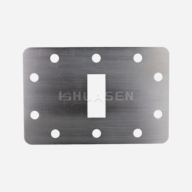
| Fixed Waveguide Short Plate | VSWR ≥ 60 (Return Loss ≤ 0.05 dB) | Sets a bar for reflection with a nearly perfect coefficient |
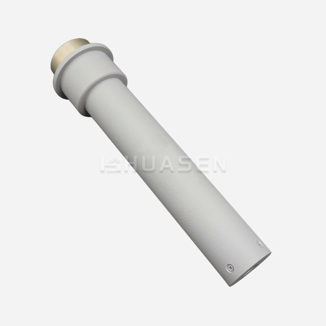
| Accurate Waveguide Parts | 1/4λ, 1/8λ, 3/8λ (±0.005 mm length tolerance) | Adds a known electrical length to the gearbox setting |
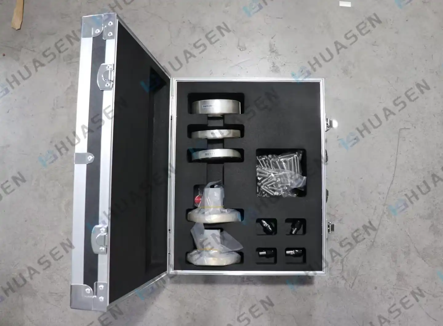
| Storage Case | Aluminum alloy with foam inserts | Keeps standards safe while being stored and moved |
| Connection Hardware | Stainless steel alignment dowels and torque-rated screws | Consistent, damage-free links are made. |
Conclusion
TRL calibration changes waveguide measurements from rough estimates to precise metrology. This lets engineers firmly describe parts that work at microwave and millimeter-wave frequencies. Moving the reference plane directly to the waveguide interface gets rid of the parasitic effects that are most noticeable at high frequencies. This method fixes the main problems with coaxial calibration methods. The three-standard method—Thru, Reflect, and Line—offers mathematical precision that works from X-band to sub-terahertz frequencies and keeps error levels below 0.2 dB. For execution to go well, care must be taken with mechanical accuracy, environmental stability, and upkeep procedures that keep standards intact throughout their service life. When buying teams and test engineers understand these principles, they can make smart choices about where to buy calibration tools that have a direct effect on the success of product development.
FAQ
1. How often should waveguide calibration kits be recalibrated?
Professional measurement labs usually have to adjust precise waveguide standards once a year to keep them linked to national metrology centers. This standard is changed by how often it is used. Daily measurement tasks gain from using stable artifacts for verification every three months, while occasional users can extend the time between checks to 18 months as long as storage conditions stay stable. Exposure to the environment speeds up decline. Parts used in field tests should be checked right away upon return, no matter how much time has passed.
2. Can TRL calibration be used for both laboratory and field applications?
With the right safety measures, TRL calibration works great in both settings. In the lab, you can control the environment to get the most accurate results, and in the field, TRL is better at handling changes in temperature than load-based methods. For field use, the most important things are to keep the surfaces clean and avoid damaging the flanges when they are being moved. Portable waveguide calibration kits with tough cases let you take readings on-site at radar sites or satellite ground stations that are far away.
3. What factors most significantly influence TRL calibration accuracy?
The mechanical accuracy of the standards determines the error limits. For example, the flanges must be flat within 5 micrometers, and the apertures must have dimensional tolerances of ±0.013 mm. These specifications provide the basis for accurate measures. Stability in the environment during testing is very important; temperature changes greater than ±2°C cause changes in dimensions that directly lead to phase mistakes. The accuracy of the connection depends on how well the pressure is applied and how well the alignment dowels are used. Noise floor, dynamic range, and source power stability built into the VNA set the highest level of accuracy that even the most exact testing standards can't go beyond.
Partner with Huasen Microwave for Precision Calibration Solutions
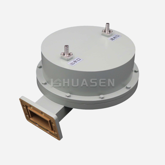
Huasen Microwave offers complete waveguide calibration kits that are designed to meet the strict needs of millimeter-wave testing in defense, aerospace, and telecommunications. Our kits come with all 12 error-correcting precision parts: waveguide-to-coaxial adapters (J and K type), matching loads with VSWR ≤ 1.03, fixed short plates with VSWR ≥ 60, and precision sections (1/4λ, 1/8λ, and 3/8λ). These parts are all made to exact measurements so that measurement error is less than ±0.15 dB. As a waveguide calibration kit maker that has been around since 1993, we blend decades of experience in RF engineering with ISO-certified production methods. We offer traceable calibration certificates and quick technical support for the lifecycle of your product. Get in touch with our sales team at sales@huasenmicrowave.com to talk about your specific measurement problems and get kit configurations that are perfect for your frequency bands and accuracy needs.
References
1. Rytting, D. K. (2001). Network Analyzer Error Models and Calibration Methods. Microwave Measurements Symposium, Hewlett-Packard Company Technical Publications.
2. Engen, G. F., & Hoer, C. A. (1979). Thru-Reflect-Line: An Improved Technique for Calibrating the Dual Six-Port Automatic Network Analyzer. IEEE Transactions on Microwave Theory and Techniques, Vol. 27, No. 12, pp. 987-993.
3. Williams, D. F., & Marks, R. B. (1991). Transmission Line Capacitance Measurement. IEEE Microwave and Guided Wave Letters, Vol. 1, No. 9, pp. 243-245.
4. Stumper, U. (2003). Uncertainty of VNA S-Parameter Measurement Due to Nonideal TRL Calibration Items. IEEE Transactions on Instrumentation and Measurement, Vol. 52, No. 3, pp. 676-679.
5. Hiebel, M. (2008). Fundamentals of Vector Network Analysis. Rohde & Schwarz GmbH & Co. KG, Munich, Germany.
6. Blackham, D. V. (1997). Application of the TRL and LRM Calibrations to the HP 8510 Network Analyzer. Cascade Microtech Application Note, Beaverton, Oregon.
Send Inquiry