RF Power Scaling Strategies Using Coaxial Power Combiner Networks






2026-07-15 17:26:22
Engineers always have to figure out how to combine multiple amplifier outputs efficiently without losing signal integrity or adding too much loss when they need to increase the RF power output across telecommunications infrastructure, radar systems, or satellite links. A coaxial power combiner is an important passive part that combines RF signals from different amplifier modules into a single high-power output. This lets system designers send kilowatts of power while keeping phase coherence, minimal insertion loss, and strong isolation between input channels, which is necessary for 5G base stations, defense radar, and broadcast applications.
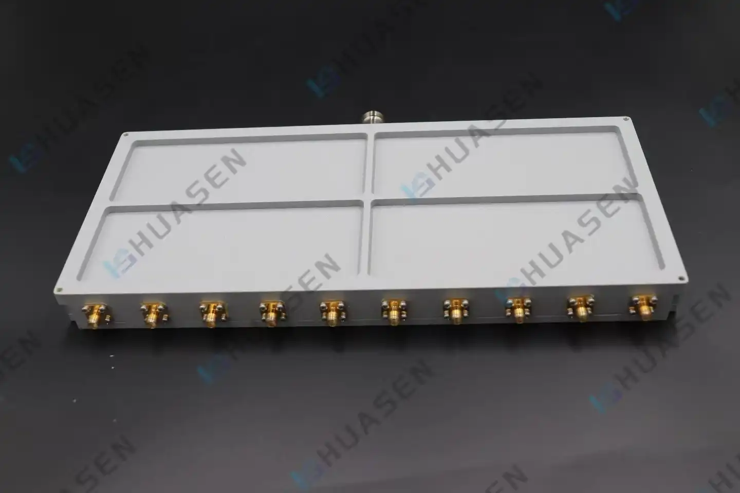
Understanding Coaxial Power Combiners and Their Role in RF Power Scaling
What Sets Coaxial Combiners Apart from Alternatives?
Coaxial combiners are very different from planar microstrip or waveguide solutions because they use the geometry of the inner and outer conductors to make a fully shielded transmission path. This circular structure is great for handling power and getting rid of heat, so it's perfect for situations where you need to be sure of steady performance during continuous high-power operation. Waveguide combiners work well at millimeter-wave frequencies but are bulky and expensive. Coaxial designs, on the other hand, are mechanically small and can be made more efficiently across the VHF through Ku-band ranges.
To make it work, you need quarter-wave transmission line sections or hybrid junction topologies, like Wilkinson, radial, or Gysel configurations, that add input signals in a way that makes sense. When more than one amplifier's outputs show up with the same phase and amplitude, vector addition works well at the output port, combining power with little loss. Unbalanced energy is thrown away by isolation resistors, which keep individual amplifiers safe from reflected power that can happen when loads don't match or when a module next to it fails.
Key Design Parameters Driving Performance
For RF power scaling to work, four technical parameters must be carefully controlled:
- Frequency Range and Bandwidth: Modern coaxial combiners can work from DC to 40 GHz, but most of their uses in radar and telecommunications are between 500 MHz and 18 GHz. To keep phase balance across the working range, transmission lines with a wider bandwidth need to be carefully designed.
- Power Handling Capacity: Based on the ratings of the connectors, the diameter of the transmission line, and how well the isolation resistor handles heat. Combiners with tens of kilowatts of CW power are needed for high-power broadcast receivers that use dozens of 500W amplifier units.
- VSWR and Return Loss: Keeping the VSWR below 1.25:1 keeps the reflected power very low, which protects the amplifiers upstream and keeps the system running efficiently. There should be no more than 20 dB of return loss across the whole band.
- Insertion Loss and Isolation: Insertion loss, which is usually 0.2 dB or less per merging stage, has a direct effect on how well the system works. Isolation greater than 20 dB between input ports stops cross-talk and intermodulation distortion, which is very important when putting together amplifiers that aren't in sync with each other.
Practical Applications Across Critical Infrastructure
In 5G massive MIMO base stations, coaxial power combiners make beamforming possible by adding the outputs of several power amps that feed antenna arrays. 256-QAM waveforms keep their modulation fidelity because they can handle high peak-to-average power ratios (PAPR) without signal compression.
Coaxial combiners are used by military radar and electronic warfare systems to get peak pulse power of megawatts or more. Extreme temperature cycling is handled by radial combiner designs during pulsed operation, keeping phase accuracy, which is important for target resolution.
These devices are used by satellite ground stations to combine power from multiple sources, and insertion loss directly affects the link budget margin. Every 0.1 dB of loss restored increases the transmission range or lowers the number of amplifiers that are needed, which saves a lot of money.
Huasen Microwave Technology Co., Ltd. Product Specifications
| Parameter | Specification |
|---|---|
| Frequency Range | DC - 40 GHz |
| Splitting Ratios | 1:2, 1:3, 1:4, 1:8, 1:10 |
| Insertion Loss | 0.2 - 0.4 dB (typical) |
| VSWR | <1.25:1 |
| Isolation | >20 dB |
| Connector Types | N-Type, SMA, 2.92mm, 5339K |
| Operating Temperature | -40°C to +85°C |
| Power Handling | Custom rated to application |
| Construction | Silver-plated brass, PTFE dielectric |
| Compliance | RoHS, MIL-STD (optional) |
Performance Optimization Strategies for Coaxial Power Combiner Networks
Minimizing Insertion Loss Through Precision Engineering
Precision engineering helps keep insertion loss to a minimum. Three things can cause insertion loss: resistance losses in wires, dielectric losses in insulators, and power loss in isolation resistors because of amplitude or phase imbalance. These problems are directly fixed by more advanced manufacturing techniques.
Skin effect losses at microwave frequencies can be cut down by treating copper wires with silver or gold in a coaxial power combiner. Connector quality is very important. Machined brass with very tight tolerances makes sure that mating cycles can be repeated without damage. PTFE or air dielectrics lower the dissipation factor, especially above 10 GHz, where dielectric losses rise quickly.
To balance the phase and amplitude across all input ports, manufacturing tolerances must be very small. The electrical lengths of transmission lines must match to within a few degrees. This can be done with CNC cutting and tuning after production. It's important to carefully check the amplifier modules that feed the combiner, because phase shift due to changes in temperature or age can make the combination less effective, turning RF power into waste heat in isolation resistors.
Thermal Management Strategies for High-Power Continuous Operation
In Wilkinson or Gysel topologies, isolation resistors get rid of unbalanced power as heat. Even small imbalances cause big thermal loads at kilowatt output levels. Integrated heatsinks that use forced air or liquid cooling stop resistor temperatures from rising too high, which would change resistance values and make the balance even worse in a destructive feedback loop.
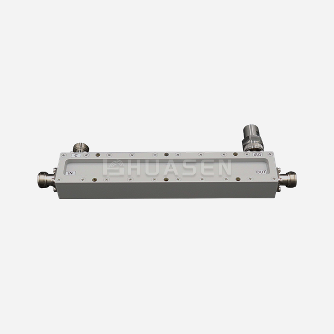
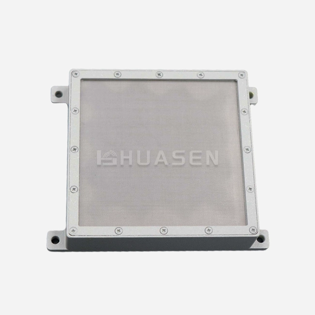
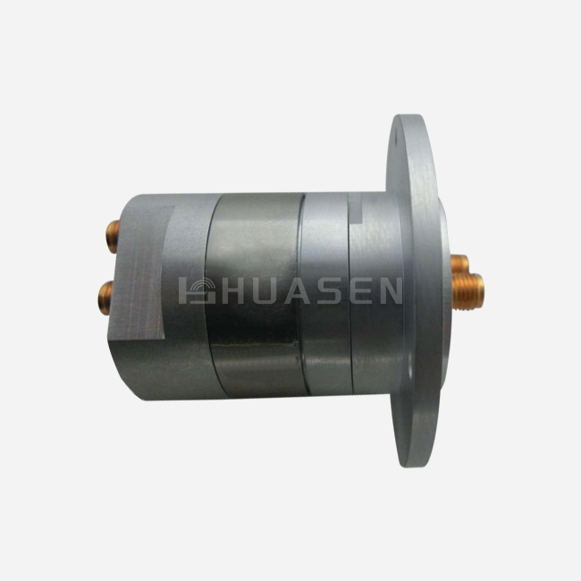
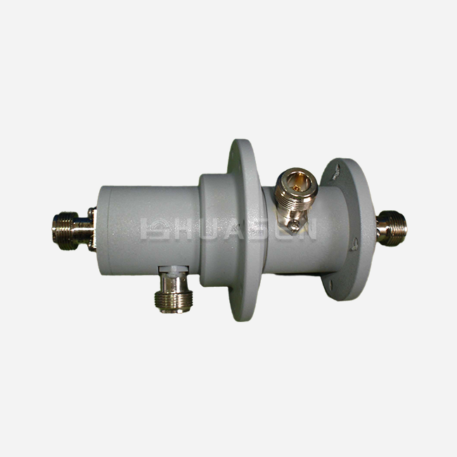
This problem can be solved by Huasen Microwave's radial line combiner technology, which has a symmetrical radial geometry that spreads thermal loads evenly across isolation elements. With standard high-power connectors like N-type, 7/16 DIN, or precision 2.92 mm and wide-body coaxial construction, these designs work reliably in temperatures ranging from -40°C to +85°C.
Protocols for testing make sure that the device is thermally stable by burning it in for a long time at full CW power. Using a Vector Network Analyzer (VNA) to measure insertion loss, VSWR, and isolation before and after temperature cycling shows that they stay within the acceptable ranges. This means that installed systems will be reliable for a long time.
Selection Criteria and Decision-Making Framework for Power Combiner Networks
Defining Technical Requirements Aligned with System Architecture
The buying process starts with a clear description of the frequency range. Combiners with a frequency range of 698 to 2700 MHz may be needed by multi-band base stations to join the LTE and 5G bands. Radar uses, on the other hand, need a narrower instantaneous bandwidth but higher peak power handling.
When figuring out the power rating, you have to look at the duty cycle, the peak envelope power, and the current. A pulsed radar transmitter that puts out 10 kW of power at 10% duty cycle puts different heat stress on materials than a broadcast transmitter that sends out 2 kW of power all the time. Give both the CW and peak ratings, as well as any modulation characteristics that apply.
The budget for the system link determines the VSWR and insertion loss goals. For every 0.5 dB of insertion loss, the amplifier output needs to be higher to keep the transmit power the same. This makes operations more expensive and heat management more difficult. In the same way, VSWR above 1.5:1 can cause amplifier foldback protection to kick in or speed up the aging process of a device.
Comparative Analysis of Manufacturers and Product Lines
| Manufacturer | Frequency Coverage | Typical Insertion Loss | Customization Lead Time | Technical Support |
|---|---|---|---|---|
| Mini-Circuits | DC-40 GHz | 0.3-0.5 dB | Limited (Catalog) | Standard |
| Pasternack | DC-18 GHz | 0.4-0.6 dB | 2-4 weeks | Standard |
| Huasen Microwave | DC-40 GHz | 0.2-0.4 dB | 3-6 weeks | Comprehensive |
| Anaren | 500 MHz-18 GHz | 0.3-0.5 dB | 4-8 weeks | Application-focused |
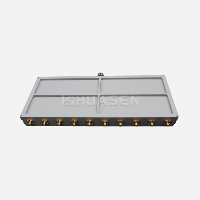
Huasen Microwave stands out because it offers a range of coaxial power combiner power-splitting ratios (2-way, 3-way, 4-way, 8-way, and 10-way setups) and a radial line design that provides excellent high-frequency stability. Standard connectors like SMA, 2.92mm, and N-Type make sure that the new system works with the old one, which cuts down on the time and money needed for integration.
Custom versus Off-the-Shelf: A Procurement Decision Matrix
Catalog products are ready to ship right away and have lower unit costs, making them a good choice when system needs are closely related to standard offerings. Custom designs are worth the longer wait times and higher initial cost when:
- Frequency bands are not in the normal catalog ranges.
- Because of physical area limits, non-standard form factors are needed.
- Extreme environmental requirements like MIL-STD shock/vibration, salt fog, and radiation hardness must be met.
- High-volume production lets one-time engineering costs be spread out over time.
Using manufacturers with in-house design skills early on in the development process lets you co-optimize the combiner and amplifier characteristics, which often leads to better system-level performance than putting together different catalog components.
Application Case Studies Demonstrating Effective RF Power Scaling
Case Study: 5G Macro Cell Base Station Power Amplification
A tier-one mobile network operator setting up 5G Massive MIMO base stations had to figure out how to feed a 64-element antenna array with eight 100W amplifiers that worked across 3.3–3.8 GHz. Some important needs were insertion loss below 0.3 dB, VSWR below 1.2:1, and temperature stability from -20°C to +60°C in outdoor settings.
An 8-way radial coaxial combiner with built-in thermal management was used for the solution. The phase balance was kept within ±3 degrees by using silver-plated brass and precise cutting. Deployment in the field showed:
- Combined output power: 785W (98.1% combining efficiency)
- Spectral mask compliance: maintained across the full temperature range
- Zero failures: 18 months of running in more than 500 places with no failures
This implementation proved that properly designed combiner networks allow power scaling without using a single high-power amplifier, which can be unreliable and hard to control when it comes to temperature.
Case Study: S-Band Weather Radar Upgrade
A weather service had to combine four 2.5 kW pulsed amplifiers at 2.8 GHz in order to switch from an old klystron-based weather radar to a solid-state design. Critical factors included peak power handling, pulse accuracy, and long-term dependability for 24 hours a day, seven days a week.
A 4-way Gysel combiner topology gave the needed thermal and isolation performance. During amplifier transients, unbalanced power was lost through isolation resistors that were mounted on liquid-cooled cold plates. The results of the measurements showed:
- Peak combined power: 9.8 kW (98% efficiency)
- Pulse rise time: less than 50 ns (no loss of performance compared to single amplifier)
- Mean time between failures: more than 40,000 hours
The upgrade cut lifetime costs by 40% compared to replacing the coaxial power combiner klystron and made it easier to keep by adding redundant amplifier units and the ability to handle a gradual decline.
Conclusion
To effectively scale RF power through coaxial combiner networks, you need to pay close attention to electrical performance, heat management, and the way you buy things. When you know the pros and cons of insertion loss, isolation, and power handling, you can make a choice that fits the needs of your system. Case studies from real life show that well-designed solutions can combine efficiencies of over 98% while also providing long-term dependability in demanding aerospace, radar, and telecommunications applications. When engineers use strategic buying, they weigh the benefits of using a catalog against the benefits of custom optimization. They also look at the total cost of ownership, which includes technical support, and plan tasks ahead of time. This puts engineering teams in a good position to build strong infrastructure that can keep up with changing bandwidth and power needs.
FAQ
1. What frequency ranges do coaxial power combiners typically support?
Coaxial combiners work from DC to millimeter waves, and most practical designs work from 500 MHz to 40 GHz. Lower frequency uses (HF/VHF below 500 MHz) have trouble with size because quarter-wave parts get too big to use. Millimeter-wave designs above 40 GHz switch to waveguide technologies because of issues with manufacturing tolerances and loss. However, specialized coaxial systems can still be used up to 60 GHz.
2. How do coaxial combiners differ functionally from waveguide combiners?
Coaxial architectures use concentric conductors to allow TEM mode propagation, which allows for wideband operation and small mechanical packaging that works with standard RF connectors. Waveguide combiners use hollow rectangular or circular conducting structures that support TE/TM modes. They have lower loss and can handle more power at millimeter-wave frequencies, but they are big and need precise flanged interfaces. The choice between these technologies is based on the regularity of the application, the power level, and the physical limitations.
3. What testing verifies combiner performance within RF systems?
Using VNA S-parameter measurements to set a baseline for performance, you can find out how much insertion loss, return loss, and isolation there is across the operating band. If you test something at high power under-rated CW or pulsed conditions, it checks for thermal stability and shows any possible passive intermodulation (PIM) problems. Measurements of phase and amplitude balance across all input ports show that the combining works well, and thermal imaging finds hotspots that could be signs of a manufacturing defect or resistor degradation.
Partner with a Trusted Power Combiner Supplier
Huasen Microwave designs Coaxial Power Combiner systems that work best in radar, aerospace, defense, and telecommunications. Our DC-40 GHz product line includes radial line technology for high-frequency stability, flexible splitting ratios ranging from 2-way to 10-way configurations, and standard connectors for easy integration. With more than 30 years of experience in RF design and the ability to make any changes you want, we can turn difficult power scaling needs into reliable hardware that is ready for production. Email our applications engineering team at sales@huasenmicrowave.com with your requirements to talk about them, get technical datasheets, or get volume pricing that fits your budget and delivery schedule.
References
1. Wilkinson, Ernest J. "An N-Way Hybrid Power Divider." IRE Transactions on Microwave Theory and Techniques, vol. 8, no. 1, 1960, pp. 116-118.
2. Cohn, Seymour B. "A Class of Broadband Three-Port TEM-Mode Hybrids." IEEE Transactions on Microwave Theory and Techniques, vol. 16, no. 2, 1968, pp. 110-116.
3. Pozar, David M. Microwave Engineering, 4th ed. Wiley, 2011, Chapter 7: Power Dividers and Directional Couplers.
4. Saleh, Adel A.M. "Planar Electrically Symmetric N-Way Hybrid Power Dividers/Combiners." IEEE Transactions on Microwave Theory and Techniques, vol. 28, no. 6, 1980, pp. 555-563.
5. Pitzalis, Otto and Robert A. Gilson. "Tables of Impedance Matching Networks Which Approximate Prescribed Attenuation Versus Frequency Slopes." IEEE Transactions on Microwave Theory and Techniques, vol. 19, no. 4, 1971, pp. 381-386.
6. Bahl, I.J. and P. Bhartia. Microwave Solid State Circuit Design, 2nd ed. Wiley-Interscience, 2003, Chapter 12: Power Combining Techniques.
Send Inquiry