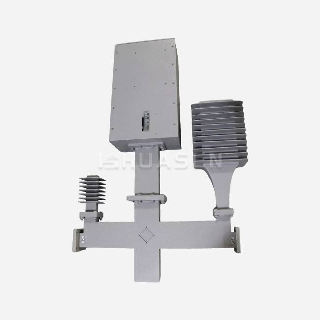
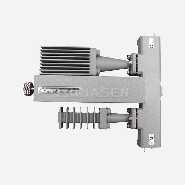
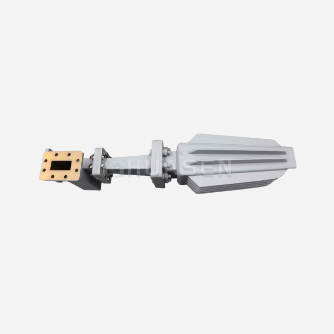
Multi Bend Waveguide in Dense Platforms






2026-07-15 17:26:29
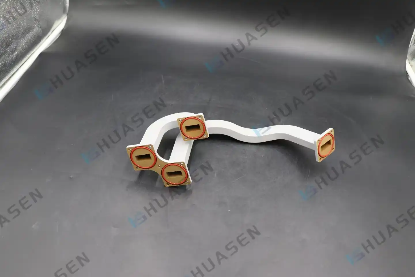
Engineers often have to figure out how to get microwave signals through small spaces without losing power efficiency or phase stability when they're making high-frequency transmission systems for things like phased array radar modules and 5G base station frontends. Multi-bend waveguide parts solve this problem by combining several directional changes into a single, well-machined part. These strong, continuous structures can go around hurdles inside satellite packages, flying radars, and communication hubs. They do this by getting rid of lossy flange joints and keeping the signal integrity across high-frequency bands. This method replaces chains of heavy bends with straight sections. This cuts down on assembly weight, insertion loss, and quality control time. For system designers, this means faster installation processes and a lower total cost of ownership.
Understanding Multi Bend Waveguides: Theory and Design Principles
At the centre of each multi-bend waveguide is an electromagnetic path that has been carefully planned. A multi-bend waveguide assembly, on the other hand, guides millimetre-wave energy through two or more direction changes, such as E-plane bends, H-plane bends, or a mix of the two. It does this while keeping the cutoff frequency and impedance match that are required by the waveguide standard. To keep mode conversion and reflection spikes that lower voltage standing wave ratio (VSWR) from happening, each bend radius needs to be worked out. If everything is put together properly, the whole thing works like a single, low-loss gearbox line that can handle peak power levels in the kilowatt range without arcing or overheating.
Electromagnetic Properties and Frequency Response
A multi-bend waveguide structure's frequency response is affected by how smooth the walls are, how well the material conducts electricity, and the ratio of radius to wavelength at each bend. When radii are too small, reactive discontinuities happen that move resonant nulls, but when curves are too big, insertion loss stays almost flat across the band. From X-band to Ka-band, good designs get VSWR below 1.15:1, keeping both amplitude flatness and group delay linearity. This is important for wideband radar chirps and high-order modulation schemes in 5G backup lines. Skin-effect losses can be predicted as long as the surface roughness is less than 0.8 µm Ra. This is true even at millimetre-wave frequencies, where the current penetration depth drops to microns.
Material Selection and Bend Geometry
To pick the right alloy, you have to weigh the electrical performance, the ease of working with it, and the cost over the product's lifetime. Copper that doesn't contain oxygen has the lowest resistive loss and can be silver-plated for maximum conductivity. This makes it the gold standard for laboratory-grade parts and satellite payloads where every decibel counts. Aluminium 6061 has a good loss at a very low weight, making it perfect for flying platforms and UAV pods that need to save weight. Bend angles are usually between 45° and 90°, and the wall width is set so that it can handle being pressurised with SF₆ or dry nitrogen for high-power use. Dimensional tolerances of 0.025 mm ensure consistent flange alignment, which saves time and money on costly field rework during system integration.
Advantages Over Straight and Flexible Alternatives
Using a single rigid multi-bend waveguide assembly instead of several flanged elbows cuts down on the number of mating planes, which directly lowers passive intermodulation (PIM) artefacts and hermetic seal failure points. Rigid multi-bend waveguide units keep their phase stability better than flexible waveguide units, even when they are vibrating and changing temperatures. This is important for synthetic aperture radar coherence and precise interferometry. The smooth inside gets rid of the corrugated-wall losses that come with flex guides, making the usable bandwidth and peak power rating bigger. System designers have more options for installation without giving up the ruggedness needed to meet MIL-STD-810 shock and MIL-STD-461 electromagnetic compatibility standards.
Comparative Analysis: Multi-Bend Waveguide vs Alternatives
To choose the best signal routeing method, you need to know how to balance electrical performance, space limitations, and long-term durability. Each technology has its own strengths, but the Multi-Bend Waveguide really shines when dense platforms need high signal quality and small areas.
Multi-bend waveguides vs. straight sections with elbows
Straight waveguide segments joined by separate 90° elbows offer modularity, which lets technicians in the field put together paths on the spot. That freedom comes with a price: each pair of flanges adds return loss, and stacked tolerances can make the total VSWR go over the limits allowed by the standard. Multi-bend waveguide assemblies get rid of the need for intermediate flanges. This cuts total insertion loss by 0.2 to 0.5 dB per transition and reduces the overall length by up to 30% through better 3D routeing. The combined design also makes closing under pressure easier, which lowers the number of failed leak tests during final acceptance.
Multi-bend Waveguide vs. Coaxial Cable
A lot of people use cable links below 18 GHz because they are easy to set up and have a lot of providers. But above 26 GHz, cable loss increases very quickly, and multichannel phased arrays can't use phase-matched sets because they are too expensive. Rigid waveguide keeps insertion loss below 0.05 dB/GHz in the Ka-band and above, and it can handle peak powers that would arc most coaxial dielectrics. But there aren't as many route options because waveguide lines have to be built into the platform from the beginning. On the other hand, cable layouts can be changed at the last minute.
| Parameter | Multi Bend Waveguide | Straight + Elbows | Coaxial Cable (>26 GHz) |
|---|---|---|---|
| Insertion Loss (dB/m) | 0.03–0.08 | 0.08–0.15 | 0.5–1.2 |
| VSWR (typical) | <1.15:1 | 1.20:1–1.30:1 | 1.25:1–1.40:1 |
| Peak Power (kW) | >50 | 30–50 | 2–10 |
| Weight (relative) | 1.0× | 1.3× | 0.6× |
| Installation Flexibility | Low (custom fit) | Medium | High |
Multi Bend Waveguide vs Flexible Waveguide
Flexwaveguides can connect parts that move, like arms and joints that can bend in different ways. Because the inside wall is curved, each ripple spreads energy out. This makes it so that only a few kilowatts of power can be used at a time and doubles the amount of energy lost per metre. When bent over and over, metal bellows wear out over time. This means that they don't last as long in high-cycle settings. A multi-bend waveguide gives up articulation in exchange for repeatability: once it's set up, it keeps its phase and amplitude fixed through millions of temperature changes. This means that it has to work well for ten years as the core of fixed infrastructure, like test rooms, ground connections, and base stations.
Procurement Guide: Selecting and Buying Multi-Bend Waveguides
You have to find a balance between technical needs and the realities of the supply chain in order to buy custom waveguide assemblies. When you follow a plan, you get the things you need on time and can easily add them to your platform without having to pay a lot of money for extra work.
Defining Technical Requirements
First, write down the frequency range, the strongest VSWR, the power level, and how much the noise is affecting the area. Pick the waveguide standard (WR-90, WR-62, WR-28, etc.) and the type of flange (UG-series, CPR, or different designs). Manufacturers use these STEP files to set up CNC bending sequences and make sure the metal fits right before they cut it. Give 3D CAD models that show the patterns of the mounting bolts and the areas of clearance. For high-power sealing, make it clear if there are any ports for pressurisation. Also, list the device's highest and lowest temperatures so that the right O-ring materials can be chosen.
Material and Plating Choices
The most loss is avoided by copper that doesn't have air and has silver plating on the inside. However, it costs more and takes longer to electroplate. Aluminium alloys are cheaper and lighter, and they can be used for links that don't need more than 10 kW of power. Iridite, chromate conversion coating, and MIL-spec paint are all good choices for the outside because they keep out salt fog and humidity. This is very important for marine and outdoor setups. To avoid delays at customs and checks by regulators later on, make sure you get material certifications and proof that they follow RoHS rules right away.
Supplier Evaluation and Customisation Capabilities
To keep tight control over tolerances and speed up iteration cycles, work with companies that can bend, machine, and plate their own Waveguide Bend Assembly products. The company should be approved by ISO 9001 and AS9100. These show that the company has quality control systems that mark each bend and measure the thickness of the metal. Check how long it takes to make a sample. First articles from skilled shops usually arrive in four to six weeks, but for sellers who use outside subcontractors, it can take up to twelve weeks. Look at VNA sweeps from previous projects to make sure that data can be used again and that they match up with models.
This combined method is shown by Huasen Microwave's multi-bend waveguide solutions, which let you choose your own bent angles, arm lengths, and interfaces based on their 30 years of experience making RF products. Different route issues that happen in satellite transponders, phased array subarrays, and millimetre-wave test systems can be fixed with flexible measurement changes and pressurisation seals that can be changed to fit the needs of the system.
Lead Times, Bulk Ordering, and Pricing Strategies
Shipping for stock bends can happen in days, but for custom shapes, you need to make tooling parts and tune them after the bend, which can take up to eight weeks during busy times. You can work out a big deal if you need to make more than 50 units. As the tools are used up, the price of each piece will go down by 20 to 40 per cent. Want to find ways to save money? Ask for detailed price lists that break down the costs of material, cutting, coating, and test labour. One way to save 15% while still staying within your loss budget is to switch from silver plating to gold plating. Set up a framework that deals with delayed delivery goals to keep track of your cash flow and warehouse stock without limiting your schedule.
| Order Quantity | Unit Price (USD) | Lead Time (Weeks) | Tooling Charge |
|---|---|---|---|
| 1–10 units | 1,200–1,500 | 6–8 | 800 (one-time) |
| 11–50 units | 900–1,100 | 8–10 | 800 (one-time) |
| 51–200 units | 700–850 | 10–12 | Waived |
| >200 units | 550–700 | 12–14 | Waived |
Applications and Case Studies of Multi Bend Waveguides in Dense Platforms
Multi-bend waveguide assemblies improve performance and make integration easier in real-world applications in the defence, aerospace, and telecommunications industries. These examples show how customised waveguide routing can help with important issues.
Telecommunications: 5G Millimetre-Wave Base Stations
For urban small-cell deployments, radio heads that are small enough to fit on utility poles and building facades are needed. A top carrier in North America got rid of different straight sections and bends and replaced them with special Ka-band multi-bend waveguide kits. This cut the size of the box by 25% and the time it took to put it together from 45 minutes per unit to 20 minutes. The combined design also increased the VSWR cushion, which decreased field failures caused by loose flange nuts in wind and ice loads.
Aerospace: Satellite Payload Feed Networks
A business LEO system user needed multi-beam radio feed networks that were light and matched in phase. In the past, flex-guide belts had too much loss at the Q-band and cracked easily during thermal vacuum testing. When rigid multi-bend waveguide assemblies made from aluminium 6061 with gold-plated interiors were used instead, insertion loss dropped from 1.8 dB to 0.6 dB per path. This increased the downlink margin by 1.2 dB, which is the same as adding 30% more transmit power without spending any more money on amplifiers.
Defence: Airborne Active Electronically Scanned Array (AESA) Radar
For a program to improve fighter jets, 128 transmit and receive channels had to be routed through a small nose radome structure. Even though the temperature went from -40°C to +85°C, the Multi-Bend Waveguide modules were able to move around avionics boxes and structural ribs and keep the phase accuracy within ±5° across all channels. The smooth bends got rid of 256 possible PIM sources, which made sure that radar cross-section signatures were low and that strict requirements for electromagnetic interference (EMI) were met.
Emerging Trends: 6G Terahertz Links and IoT Backhaul
Waveguides are getting smaller to millimetres as wireless standards move toward sub-terahertz frequencies. This makes precise bending even more important. Research prototypes at 140 GHz show that multi-bend waveguide assemblies made with additive manufacturing can achieve the same level of loss as traditional machining while making it possible to make shapes that can't be made with a mill. Internet of Things (IoT) gateways used in smart cities use small multi-band waveguide designs to fit antennas, filters, and amplifiers into weatherproof cases that are no bigger than a smartphone. This speeds up the deployment of sensor networks for monitoring the environment and managing traffic.
These case studies all have one thing in common: waveguide bend assemblies and multi-bend waveguide systems are the link between theoretical design and hardware that can be used when space limitations meet strict RF performance standards.
Conclusion
Multi-bend waveguide assemblies represent a mature yet continually evolving solution for signal routing in space-constrained, high-frequency systems. By consolidating multiple directional transitions into a single precision component, they reduce insertion loss, simplify sealing and pressurisation, and eliminate failure-prone flange interfaces that plague modular architectures. Material advances—from oxygen-free copper to lightweight aluminium alloys—combined with CNC bending precision and rigorous VNA testing ensure these assemblies meet the stringent demands of 5G infrastructure, satellite payloads, and defence radar platforms. Procurement success hinges on early collaboration with experienced manufacturers who translate CAD models into production-ready hardware, manage supply-chain logistics, and provide the technical support necessary to navigate complex specifications and certification requirements.
FAQ
1. What causes signal loss in multi-bend waveguide assemblies, and how can it be minimised?
Signal loss arises from resistive dissipation in the waveguide walls and reflections at impedance discontinuities. Tight bend radii introduce reactive mismatch, while surface roughness scatters energy at millimetre-wave frequencies. Minimising loss requires selecting high-conductivity materials—oxygen-free copper or aluminium with silver or gold plating—and maintaining bend radii above two wavelengths. Post-machining electropolishing smooths interior surfaces, and VNA-guided tuning adjusts flange positions to null residual reflections across the operating band.
2. How do I choose between a custom multi-bend waveguide design and modular straight sections?
Custom assemblies make sense when flange count exceeds four, space is severely limited, or phase matching across multiple channels is critical. Modular straight sections offer flexibility for prototype builds and field repairs. Evaluate total lifecycle cost: custom multi-bend waveguide bends carry higher upfront tooling charges but lower recurring assembly labour and fewer spare parts. For production quantities above 50 units, integrated designs typically break even within the second order.
3. Which supplier qualifications should I prioritise during vendor selection?
Look for ISO 9001 and AS9100 certifications, evidence of in-house CNC bending and plating capabilities, and a track record of delivering VNA-tested assemblies with full dimensional reports. Request references from aerospace or defence programmes requiring MIL-STD compliance. Evaluate responsiveness during the RFQ phase: vendors who ask detailed questions about mounting constraints and power budgets demonstrate engineering depth that translates into fewer design iterations and faster qualification.
Partner with Huasen Microwave for Tailored Multi Bend Waveguide Solutions
Huasen Microwave brings over three decades of precision RF manufacturing to your most demanding signal-routing challenges. Our Multi Bend Waveguide assemblies support diverse bending forms and specifications, with flexible adjustments for dimensions, bending angles, arm lengths, and interface standards. Customizable pressurization sealing options ensure reliable high-power operation in satellite transponders, phased array subarrays, and base station frontends. As an experienced Multi Bend Waveguide manufacturer, we offer comprehensive design assistance, rapid prototype turnaround, and rigorous quality control validated by VNA testing and CMM inspection. Contact our engineering team at sales@huasenmicrowave.com to discuss your application requirements, request technical datasheets, or obtain a detailed quotation for volume production. Let us transform your complex routing constraints into streamlined, high-performance assemblies that accelerate your time to market.
References
1. Pozar, David M. Microwave Engineering, 4th ed. Wiley, 2011.
2. Collin, Robert E. Foundations for Microwave Engineering, 2nd ed. IEEE Press, 2001.
3. Balanis, Constantine A. Advanced Engineering Electromagnetics, 2nd ed. Wiley, 2012.
4. Matthaei, George L., Leo Young, and E.M.T. Jones. Microwave Filters, Impedance-Matching Networks, and Coupling Structures. Artech House, 1980.
5. Rizzi, Peter A. Microwave Engineering: Passive Circuits. Prentice Hall, 1988.
6. Saad, Theodore S. Microwave Engineer's Handbook, Vol. 1. Artech House, 1971.
Send Inquiry