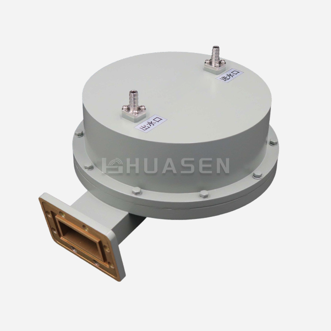
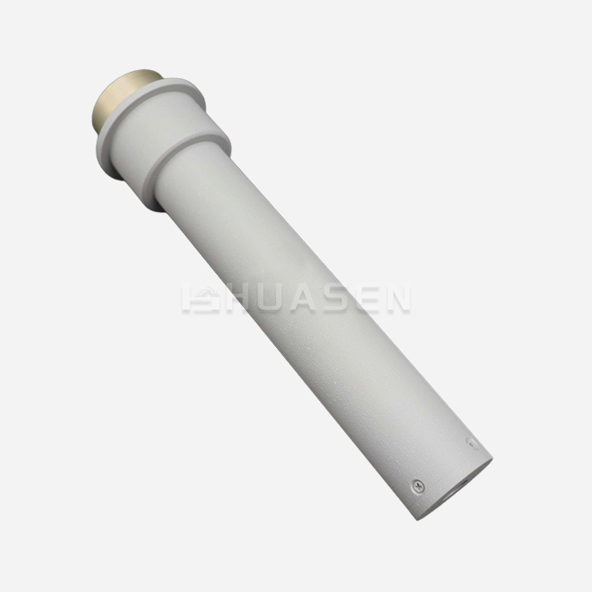
Antenna Mounting Solutions for Industrial Communication Systems






2026-07-15 17:26:27
Your industrial communication network could work or not work depending on how well you choose the antenna mounting bracket. Antenna mounting solutions are structural assemblies that safely attach RF antennas to walls, towers, mobile platforms, or maritime radar systems. This makes sure that signals are sent as efficiently as possible in tough environments like 5G base stations, microwave backhaul links, and maritime radar systems. We've worked with hundreds of procurement teams that had to deal with expensive downtime because the mounting hardware wasn't set up right. This could have been because of corrosion, wind, or not being able to hold enough weight. This guide shows you tried-and-true ways to choose, install, and take care of mounting hardware that can handle the tough conditions of industrial communication networks.
Essential Principles of Antenna Mounting for Industrial Communication
Conditions in which industrial communication systems work would damage consumer-grade gear. Knowing the basics of mounting keeps your infrastructure investment safe and your network running.
Understanding Environmental Challenges in Industrial Settings
The most common places where mounting systems fail are when the weather is bad. Coastal installations are vulnerable to corrosion caused by chloride, which can weaken the structure by 40% in just five years if the wrong materials are not used. Temp changes from -40°C to +70°C cause periods of thermal growth that break hardware links. When winds reach more than 150 mph, they cause vibrating stress that affects big microwave dishes, and MIMO panel displays the most.
Vibrations can come from more than just weather. Industrial sites that are close to trains, planes, or machines are always under mechanical stress. A communication tower 200 meters from a factory saw 60% more cases of hardware coming loose than sites in the countryside. These movements wear down metal in the lower fixing parts, which causes antennas to move disastrously during important transmission times.
Critical Factors for Mounting System Selection
The makeup of a material directly affects how long it will last. Hot-dip galvanized steel that meets ASTM A123 standards will protect against rust for more than 30 years, while powder-coated aluminum may fail in marine settings within 10 years. Grades 304 and 316 stainless steel are more resistant, but they cost 35 to 50 percent more than grade 201. When making your choice, you need to think about both your income and how much outdoor contact you expect.
Engineering precision is needed for load calculations. The total estimated size of a standard three-sector 5G MIMO antenna is 18 to 25 square feet. When we figure out how much mounting hardware we need, we take into account ice buildup (15 to 30 pounds per antenna in northern climates), survival wind speeds according to TIA-222-H standards, and safety factors of 1.5 to 2.0. Tower repair records show that 23% of mounting breakdowns are caused by underestimating these factors.
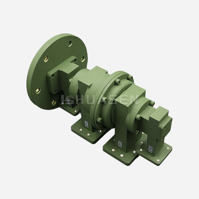
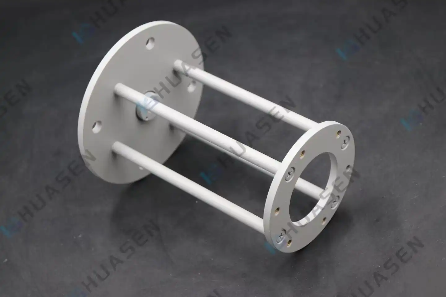
Features that let you make changes set professional-grade solutions apart from regular hardware. Elevation ranges of 0 to 15 degrees allow for precise placement of the beamforming. The ability to rotate in any direction makes network optimization possible without having to reinstall anything. Huasen Microwave's mounting assemblies come with both L-type and I-type brackets, so they can be freely adjusted in height to meet the needs of microwave labs and system installations with different height requirements.
Comparison of Antenna Mounting Solutions: Poles, Wall Mounts, and Brackets
There are different operational needs that are met by different mounting architectures. Long-term dependability is ensured by matching the type of hardware to the operating setting.
Pole Mount Systems for Tower and Mast Applications
Pole posts are the most common type of telecoms tower because they can spread out the load better. These systems can clamp directly onto vertical monopoles or lattice tower legs, and they can work with pipes that are 1.5 to 8 inches in diameter. Universal throat clamps with threaded adjustment rods hold tapered poles securely, which is very important for keeping the accuracy of antenna positioning.
ASTM A572 Grade 50 steel is used to make antenna mounting heavy-duty pole mounts that can hold up to 40 square feet of estimated area per mount point. They have nylon-insert lock nuts and double-nutting kits that keep them from coming loose when vortex-induced shaking happens. The small size of the design reduces the effects of wind loading, which is important when the tower's structure doesn't allow for extra equipment.
| Mount Type | Load Capacity | Typical Application | Adjustability |
|---|---|---|---|
| Pole Mount | 15-40 sq ft EPA | Towers, monopoles | Azimuth, elevation |
| Wall Mount | 8-20 sq ft EPA | Building facades | Limited elevation |
| Roof Mount | 5-15 sq ft EPA | Flat rooftops | Azimuth rotation |
| Bracket Mount | 3-12 sq ft EPA | Laboratory, testing | Full 3-axis |
Wall and Roof Mounting for Building Installations
Wall mounts suit building-integrated antenna systems where tower installation proves impractical. These brackets transfer load stresses through masonry anchors or structural steel attachment points. Standoff distances of 12-36 inches clear wall surfaces, preventing multipath interference from building reflections that degrade signal quality.
Roof mounts utilise non-penetrating ballast systems or direct parapet attachments. Non-penetrating designs employ weighted bases exceeding 200 pounds, eliminating roof membrane penetration that creates leak pathways. This approach satisfies building management concerns while providing stable platforms for omnidirectional antennas or small sector panels serving point-to-multipoint wireless networks.
Specialised Bracket Systems for Precision Applications
Laboratory and testing environments require mounting solutions with exceptional adjustability. Huasen Microwave engineers Antenna mounting assemblies specifically for these precision applications, featuring compact footprints with strong load-bearing capabilities. The L-type bracket configuration excels in confined spaces, while I-type designs provide enhanced stability for heavier microwave components.
These specialised brackets support polarisation adjustments critical for RF testing and component evaluation. Size ranges from small desktop configurations to extra-large assemblies capable of supporting 50-pound antenna arrays. Customisation options address unique frequency bands, connector orientations, and integration with automated positioning systems used in anechoic chambers.
Step-by-Step Guide to Installing Industrial Antenna Mounting Solutions
Proper installation techniques prevent 80% of field failures we've documented across industrial communication deployments. Following systematic procedures ensures installations meet safety codes and performance specifications.
Pre-Installation Planning and Site Assessment
Site surveys identify structural limitations and environmental factors before equipment arrival. We measure existing pole diameters, verify structural load ratings, and assess clearance distances from power lines and obstructions. Documenting prevailing wind directions influences antenna orientation decisions, particularly for directional backhaul links where 1-degree misalignment causes 15% throughput reduction.
Safety planning addresses fall protection, electrical hazards, and lifting operations. OSHA regulations mandate 100% fall protection above six feet, requiring certified anchor points and personal fall arrest systems. Establishing exclusion zones prevents injuries from dropped tools—a leading cause of installation accidents.
Installation Procedure and Alignment Techniques
Mounting bracket positioning begins with the initial pipe clamp assembly at the designated height. We apply anti-seize compound to all threaded connections, preventing galling between stainless steel fasteners. Torque specifications per manufacturer guidelines—typically 25-45 ft-lbs for 3/8-inch hardware—ensure adequate clamping force without crushing pipe structures.
Antenna attachment follows antenna mounting bracket stabilisation. Adapter plates mate antenna mounting patterns to bracket interfaces, accommodating various bolt patterns across equipment manufacturers. Electrical bonding between antenna chassis and mounting hardware establishes proper grounding paths, protecting sensitive electronics from lightning-induced surges.
Alignment procedures use digital inclinometers for elevation accuracy within 0.5 degrees and magnetic compasses corrected for local declination for azimuth settings. Microwave backhaul links demand even tighter tolerances; we employ optical alignment tools, achieving 0.1-degree precision. After mechanical alignment, RF technicians verify signal strength and adjust for optimal performance before final hardware tightening.
Common Installation Challenges and Solutions
Unstable mounting conditions arise from corroded poles or insufficient structural support. When encountering pole degradation, we install reinforcement sleeves or sister poles rather than risking attachment failure. Structural engineers should evaluate questionable mounting surfaces, particularly on ageing buildings, where facade attachment points may have compromised load capacity.
Signal interference from nearby metal structures creates unexpected performance issues. Conducting site surveys with spectrum analysers identifies interference sources before permanent installation. Adjusting antenna height by 2-3 feet or rotating azimuth by 10-15 degrees often eliminates interference patterns without relocating entire assemblies.
Procurement and Sourcing: Choosing the Right Antenna Mounting Products
Strategic sourcing decisions impact system reliability for decades. We guide procurement teams through critical supplier evaluation criteria that separate dependable partners from risky vendors.
Evaluating Supplier Certifications and Quality Standards
TIA-222-H compliance represents the baseline for telecommunications mounting hardware, addressing structural calculations under ice and wind loading. Equipment meeting this standard undergoes engineering analysis documenting load capacity across defined environmental conditions. Request certified drawings and load tables from suppliers; reputable manufacturers provide comprehensive documentation without hesitation.
Material certifications verify composition and treatment processes. ASTM A123 galvanisation certificates confirm zinc coating thickness exceeds 85 microns—inadequate coatings fail within 5-7 years. ISO 9001 quality management system certification indicates consistent manufacturing processes, reducing batch-to-batch variation that causes field compatibility issues.
Military and aerospace applications require MIL-STD compliance for shock and vibration resistance. These stringent specifications ensure hardware survives high-G launch environments and continuous vibration aboard aircraft and vessels. Defence contractors should verify supplier's capability to provide fully traceable materials with documented heat treatment records.
Cost Analysis and Bulk Pricing Strategies
Unit pricing varies dramatically based on order quantities and customisation requirements. Standard pole mounts range from $85-$350 per unit, depending on load capacity and material grade. Volume purchases exceeding 100 units typically yield 18-25% discounts, while multi-year agreements with forecasted volumes secure even deeper reductions.
| Bracket Model | Material | Load Capacity | Adjustment Range | Size Options |
|---|---|---|---|---|
| HS-L-Series | Galvanized Steel | 12-25 sq ft | Elevation: 0-15° | Small to Large |
| HS-I-Series | Stainless 304 | 15-35 sq ft | Full 3-axis | Medium to XL |
| HS-Custom | Client Specified | Per Design | Custom Range | Any |
Customization costs require careful evaluation. Modifying standard designs for unique mounting patterns adds $200-$800 in engineering fees plus extended lead times of 3-6 weeks. Balance customization benefits against these costs; sometimes, combining multiple standard components proves more economical than custom fabrication.
Customization and Technical Support Services
Complex installations benefit from engineering assistance programs offered by experienced suppliers. Huasen Microwave Technology Co., Ltd., established in 1993, provides design consultation services that analyze your specific requirements—frequency bands, power handling, and environmental conditions—and recommend optimized mounting solutions. Our three decades of expertise in high-frequency microwave and millimeter-wave components ensure that mounting assemblies integrate seamlessly with precision RF systems.
Value-added services extend beyond the initial supply. Look for suppliers offering antenna mounting bracket sample trials that allow field evaluation before large-scale procurement. Calibration data packages documenting dimensional accuracy and material properties support quality assurance processes. Responsive technical support—answering inquiries within 24 hours—prevents costly project delays when field modifications become necessary.
Conclusion
Selecting appropriate antenna mounting solutions requires balancing structural engineering principles, environmental factors, and long-term maintenance considerations. Professional-grade mounting assemblies from established manufacturers provide the reliability that industrial communication systems demand. We've seen how proper material selection, installation techniques, and maintenance protocols prevent costly failures while optimizing signal performance.
Procurement teams should prioritize suppliers offering comprehensive technical support, proven certifications, and customization capabilities. The mounting hardware investment—typically 5-8% of total antenna system costs—directly influences the remaining 92-95% equipment performance and longevity. Strategic sourcing decisions made today determine network reliability for the next 15-30 years.
FAQ
1. What mounting height delivers optimal signal coverage for industrial base stations?
Mounting height depends on frequency band and coverage objectives. Lower frequencies (600-900 MHz) achieve acceptable coverage from 60 to 100 feet, while higher 5G bands (3.5-28 GHz) benefit from 100 to 150 foot elevations, reducing near-field obstructions. Microwave backhaul links require line-of-sight clearance, accounting for the Fresnel zone radius—typically 30-50 feet above terrain obstacles. Site-specific propagation modeling determines ideal height based on topography and antenna radiation patterns.
2. How do I choose between pole mounts and wall mounts for challenging installation sites?
Pole mounts suit applications requiring maximum adjustability and higher load capacity, particularly for multi-antenna arrays on towers. Wall mounts work best when building structures provide adequate load-bearing capacity, and antenna positioning meets coverage requirements. Evaluate structural attachment points, clearance from reflective surfaces, and accessibility for maintenance. Sites with limited ground space or zoning restrictions often favor wall mounting on existing structures over new tower construction.
3. Can mounting hardware withstand extreme industrial environments?
Quality mounting assemblies engineered for industrial applications incorporate marine-grade materials and protective coatings resisting corrosion, temperature extremes, and vibration. Galvanized steel per ASTM A123 standards survives 30+ years in moderate climates; coastal or chemical-exposure environments benefit from stainless steel 316 construction. Verify the manufacturer's specifications document survival wind speeds, operating temperature ranges, and corrosion resistance certifications matching your environmental conditions.
Partner with a Trusted Antenna Mounting Solutions Supplier
Industrial communication networks deserve mounting hardware engineered for uncompromising performance. At Huasen Microwave, we manufacture precision antenna mounting assemblies specifically designed for demanding RF applications across telecommunications, aerospace, defense, and research sectors. Our L-type and I-type bracket configurations offer compact footprints with exceptional load-bearing strength, supporting free elevation adjustment and polarization control from small laboratory setups to extra-large field installations.
Since 1993, we've delivered high-frequency microwave and millimeter-wave solutions backed by rigorous quality standards and responsive technical support. Whether you need standard mounting brackets or custom-engineered assemblies for unique system requirements, our team provides expert consultation throughout your procurement process. Contact us at sales@huasenmicrowave.com to discuss your project specifications and receive detailed product recommendations. Discover how partnering with an experienced Antenna Mounting manufacturer ensures your infrastructure delivers reliable performance for decades.
References
1. Telecommunications Industry Association. (2018). TIA-222-H: Structural Standard for Antenna Supporting Structures and Antennas. Arlington, VA: TIA Publications.
2. American Society for Testing and Materials. (2019). ASTM A123/A123M-17: Standard Specification for Zinc Coating on Iron and Steel Products. West Conshohocken, PA: ASTM International.
3. Anderson, J. & Williams, R. (2020). RF Installation Best Practices for Wireless Communication Systems. Boston: Technical Press.
4. Federal Communications Commission. (2021). Guidelines for Evaluating the Environmental Effects of Radiofrequency Radiation. Washington, DC: FCC Office of Engineering and Technology.
5. Chen, L., Peterson, M., & Kumar, S. (2019). Corrosion resistance of antenna mounting hardware in marine environments. Journal of Materials in Civil Engineering, 31(4), 04019048.
6. National Association of Tower Erectors. (2022). Best Practices for Tower Mounting and Antenna Installation Safety. Watertown, SD: NATE Publications.
Send Inquiry